Week 9 - Project - A pillar Design with Master Section
AIM
Design A pillar and doghouse by considering the master section.
DESIGNING OF A PILLAR
INPUT
Master section
Master sections are the guides for design requirements which decide the component packaging after technical (Styling, Concept or Class-A) surfaces.
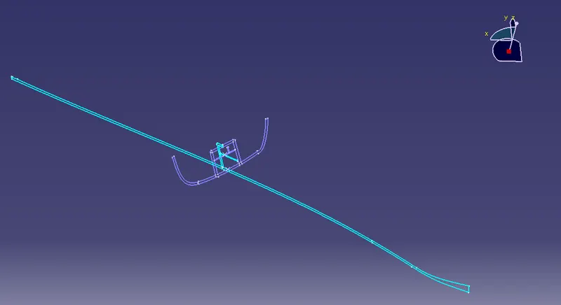
fig.1. Master section
Class A surface
It describes the final production surface data for the aesthetic parts of the car.
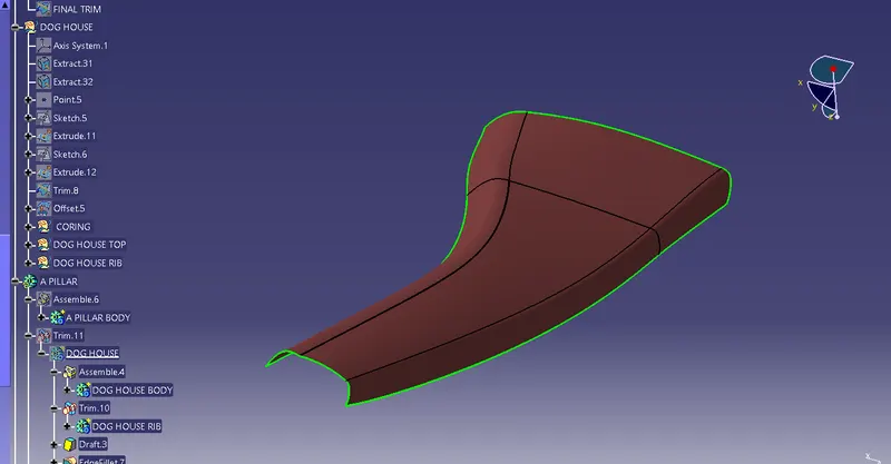
Fig.2. Class A
TOOLING AIXS FOR CLASS A SURFACE
First created the tooling axis for class A surface .In the master section the dog house is also included . The dog house is created in the main tooling direction.So we can create the tooling axis form this master section.
Bisecting method is use to create the tooling axis .
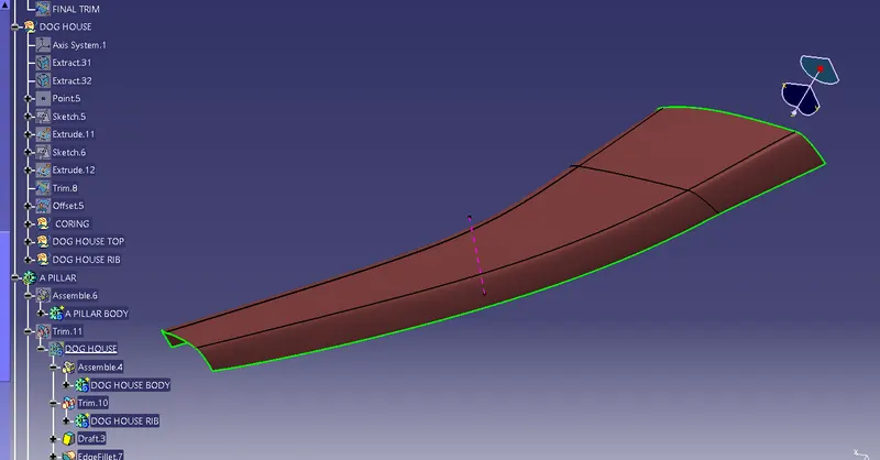
Fig.3. Tooling axis
DRAFT ANALYSIS OF CLASS A SURFACE
draft analysis performed on the class A surface using the tooling axis to check all faces of A pillar has minimum draft of 3 degree.
- Here some areas of class A surface not clearing the minimum draft .it shown in blue colour.Minimum draft on this region is 2.5 degree .
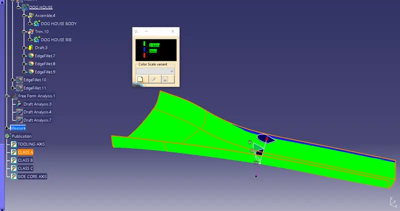
Fig.4.draft analysis of class A surface
CLASS B SURFACE
B surface means thickness of a part it is not visible it is inside part .This surface contain the engineering features of a model.
- offeseting the class A surface in required thickness to create the B surface .
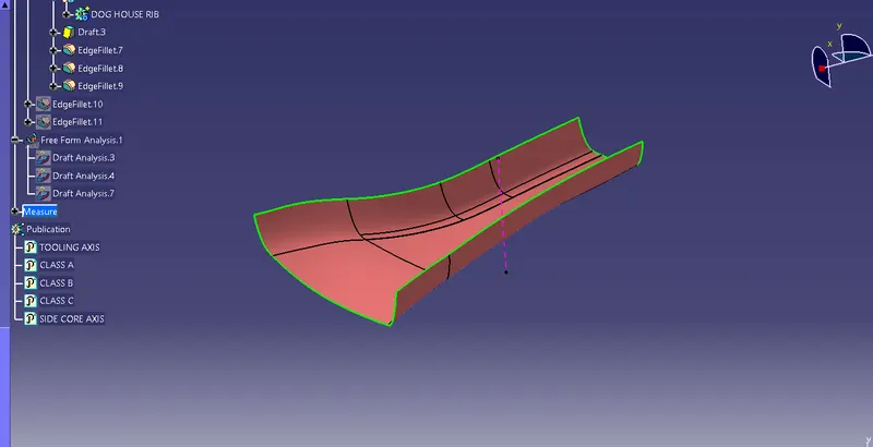
fig.5.class B surface
CLASS C SURFACE
c surface means A and B combined to give C surface. It joins the both class A and class B surfaces.
- sweep with reference surface tool is use to create the class c surface .
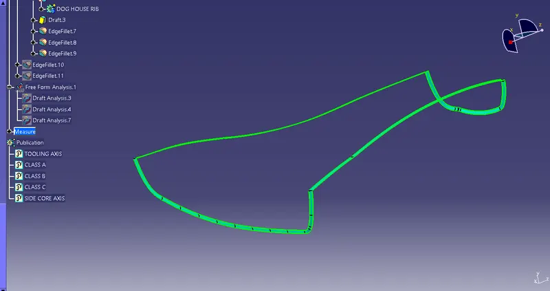
Fig.6. Class C surface
- Then join the class A and C surface and finally trim with class B surface to create the closed surface of A pillar
Solid body of A pillar is created by using the 'close surface tool'.
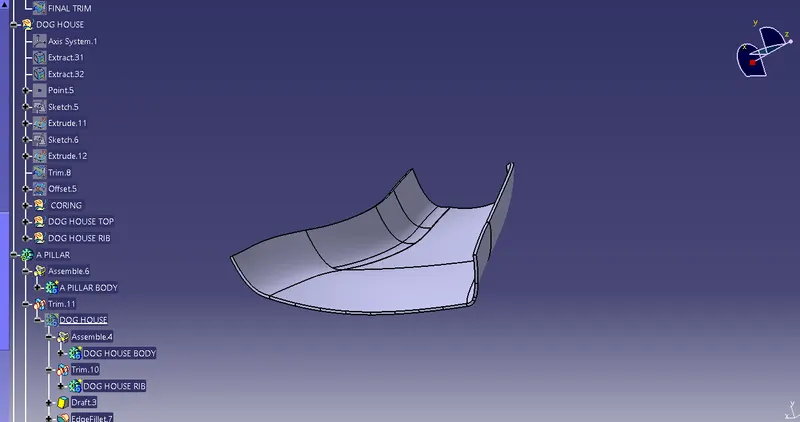
fig.7. Solid body of A pillar
- Draft analysis of A pillar body part
Here some areas of class C surface not clearing the minimum draft shown in fig.It is beause of some error in the class A surface.Class c surface is created by using class A surface as a reference.
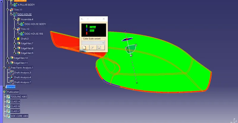
fig.8.draft analysis of solid part
DOG HOUSE DESIGN
Dog houses are designed to avoid SINK MARK created on the CLASS-A surface by screw bosses and to solve the length issues when giving screw bosses which need to be assembled to other components.
It is also useful when perpendicular screw bosses are required on the part to the tooling direction.
Extracting the sides of dog house from master section then extrude and trim operations used to create the dog house
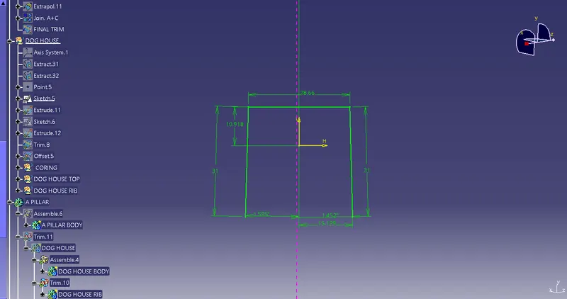
fig.9. sketch 1
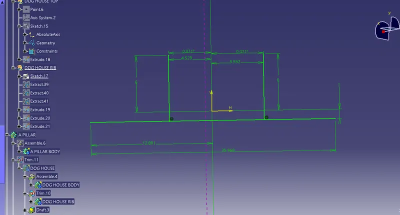
fig.10.Sketch 2
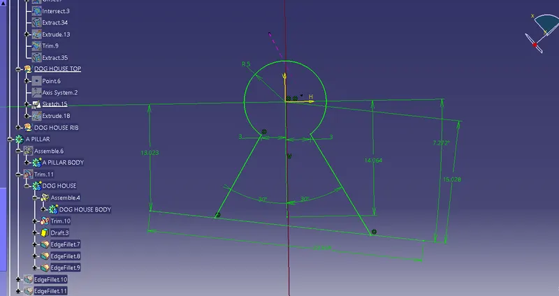
fig.11.sketch 3
- Side core Axis for dog house
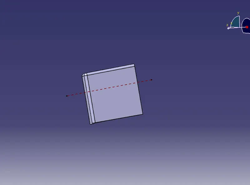
fig.12.side core axis
Since the dog house's inner walls not cleared in the main tooling direction, it created by using a side core. so we need to create the tooling axis for the side core.
DRAFT ANALYSIS OF DOG HOUSE
- draft analysis of dog house along main tooling direction
draft analysis performed on the dog house to check the draft.here master section for the dog house has minimum daft 0.5 degree on back side and remain sides clearing 1.5 degree.
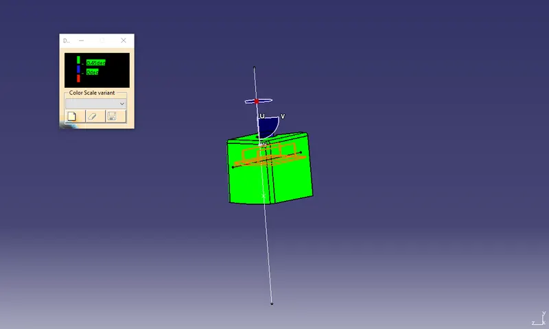
fig.13.dog house draft analysis (main tooling axis )
- draft analysis of dog house along side core axis
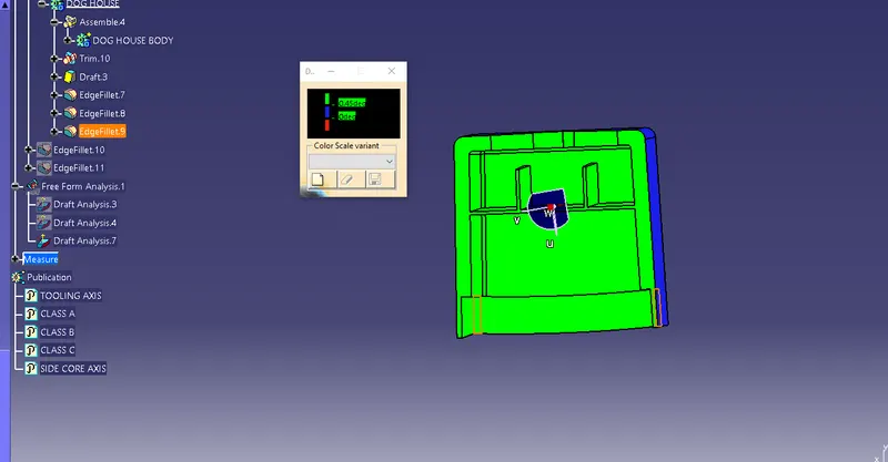
fig.14.draft analysis ( side core axis )
The dog house inner walls created by side core .so inside the dog house required minimum 0.5 degree draft for error free working of side core.
here the dog house clearing the draft on all sides .
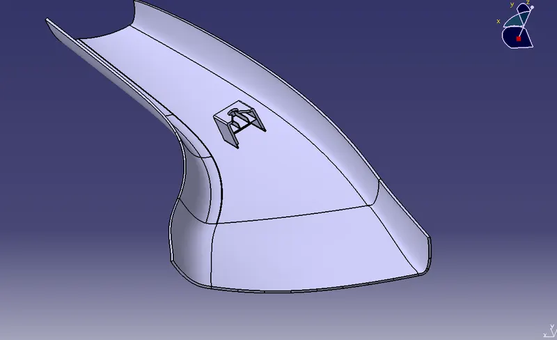
fig.15.A pillar with dog house
CONCLUSION
The A Pillar and dog house created by using master section .