Week 9 - Project - A pillar Design with Master Section
MASTER SECTION
Master section is that is the cut section view of the solid model , For this challange we need to create a Class A ,b,c & all the engineering features should made by with the reference of master section curve .
TOOLING AXIS
Sides of the part that appear parallel with the direction of draw (The axis of the cored position (hole) or insert is parallel to the up and down movement of the mold as it opens and closes) are typically angled slightly with (draft) to ease release of the part from the mold. Insufficient draft can cause deformation or damage.
TO CREATE TOOLING AXIS IN CATIA
First we need to check the component that is create based on normal axis (compass) it realated or not.
For this we need to create a line for line we need a point
place the point where surface is flat to check the draft analysis and create the line It should perpendicular to the component
Then check the normal axis and also the draft analysis passes or not.
If it is passing we can go with normal axis which in softwate by default
if it is not we need to go with making the line (tooling axis) with poin to normal to the surface that surface should be flat.
And then do the draft analysis with the refrence of tooling axis what we made.
FOR THE DOG HOUSE TOOLING AXIS
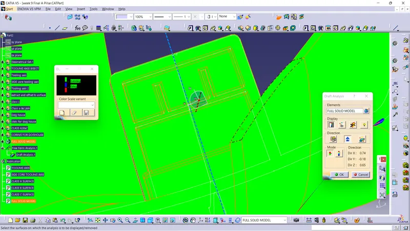
We need a side core for making the doghouse
so we need to create side tooling axis also.
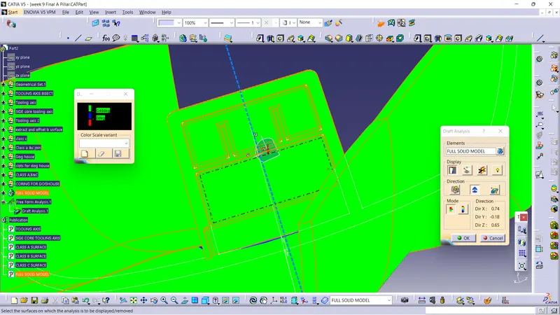
DRAFT ANALYSIS
For create a draft analysis we need a surface with no boundary.
Then give the solid part as material in customize view parameters than go for draft analysis
which is in tool bar analysis , feature draft analysis .
Then select the surface as input,
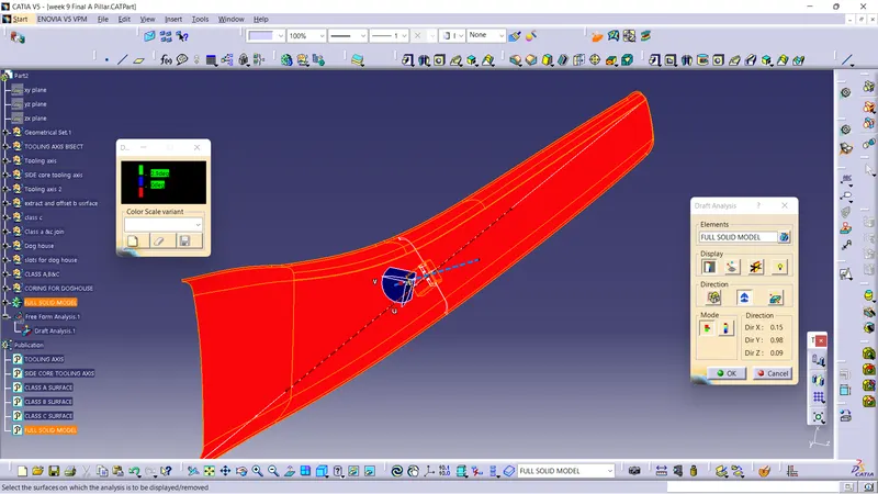
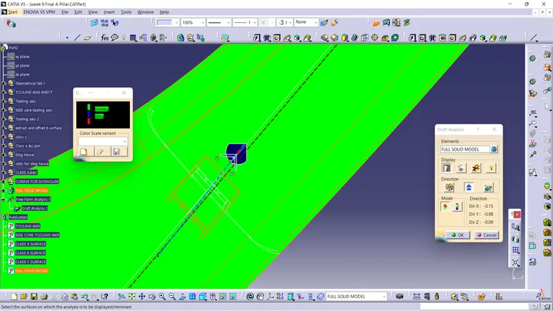
and then pic the compass , and placed in then tooling Axis what we created,
And activate the compass by clicking the compass icon in that draft analysis dialogue box .
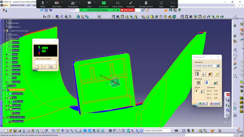
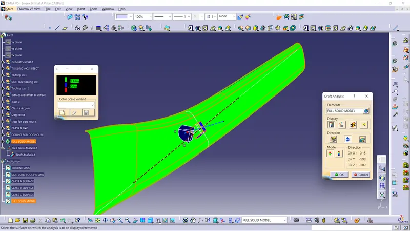
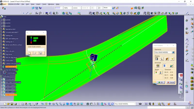
Then check the draft analysis with the help of color cooding in color showing dialogue box.
Where ever it passes it shows in green in color it shows the draft angle is perfect
If it shows red in color it shows that the no draft that is 0 deg in it.
If it shows blue color it shows that it is less than 0 deg.
In setting the color cooding based upon the costomer need or for our refrence.
Draft analysis is that check the tooling axis with the component it will pass or not , when we going for injection molding it should have proper draft angle in it.
In draft analysis it shows that where the component passes or not in injection molding with the help of tooling axis
In CATIA Software the tool which is called draft analysis in that with the help of compass we will analysis the draft or in the propre direction
Where ever it passes it shows in green in color it shows the draft angle is perfect
If it shows red in color it shows that the no draft that is 0 deg in it.
If it shows blue color it shows that it is less than 0 deg.
Sides of the part that appear parallel with the direction of draw (The axis of the cored position (hole) or insert is parallel to the up and down movement of the mold as it opens and closes) are typically angled slightly with (draft) to ease release of the part from the mold. Insufficient draft can cause deformation or damage.
All the color and values setting manually by the design engineer with the help of customer requirements.
Minimum thickness of the plastic component is 2.5 mm it an universal dimension
Because the thickness of the plastic component beyond 2.5 mm it is difficult to produce in injection molding and also the plastic component not be strength it will lose its property.
For the injection molding component it must have minimum of 3deg or more than that.
Parting line
Where the core and cavity of the injection molding machine in that meeting point of the core and cavity is called parting . it is nothing but partition between the core and cavity
If the parting line is not in proper area it affects the class A surface
A parting line, in industrial casting of molds, is the border line in which draft angles change direction. One can check the parting line in the mould or product which divides the two half, i.e; the core and the cavity of a molded part. It is sometimes a starting point for the mold parting surface.
In this particular exercise class A surface is given as input
Class B and Class C surface should we have to do it properly with the correct draft angle.
And make the component as solid body.
And do the draft analysis of that component that we have made.
process of injection molding
Overview and Characteristics Injection molding is a forming process using molds. Materials such as synthetic resins (plastics) are heated and melted, and then sent to the mold where they are cooled to form the designed shape. Due to the resemblance to the process of injecting fluids using a syringe, this process is called injection molding
FOR THIS EXERCISE
In this particular exercise class A surface is given as input
Class B and Class C surface should we have to do it properly with the correct draft angle (For this exercise c surface should be flat because the undercut draft are flat so we need to maintain the thickness with 90 deg draft from the Class A surface to the Class B surface).
And make the component as solid body.
And do the draft analysis of that component that we have made.
Procedure of creating plastic component
Input Class A surface ( it should be in single surface)
Use the join tool to join the surface
Check the boundary with the help of boundary tool.
Draft analysis
And to start creating b surface by manual extract and offset or straight offset .
Untrim the surface and trim with each other and create the Class B Surface
Then stat to create c surface which is in between the in Class A and Class B surface
C surface should have the draft angle too
And trim both the surface with Class C surface.
And to check the surface boundary and draft analysis too.
If any thing goes beyond that we need to inform the styling team to improve the surface model.
Then we need to go for solid model that is close body.
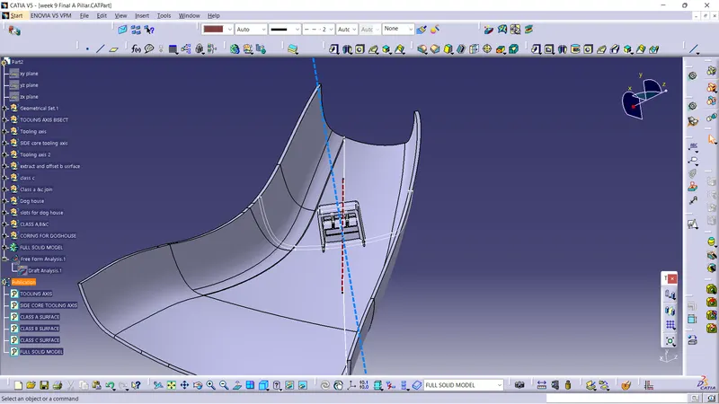
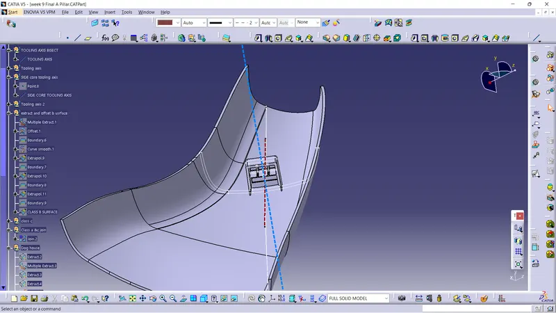
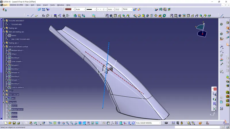
SCREEN SHORTS
THANKYOU
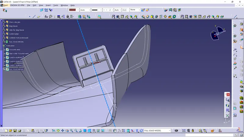
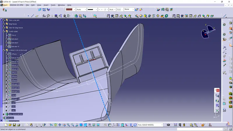
PLEASE FIND THE ATTACHEMENT OF MY CATIA MODELLING.