Week 9 - Project - A pillar Design with Master Section
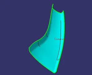
Checking Class A surface:
We should ensure that the given Class A surface has no gaps in between components. This can be checked by:
- Visual Inspection
- Using Boundary Command
It has one single outer boundary, hence the check is completed
Tooling Axis:
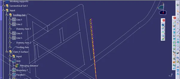
- Check visually which is the best possible tooling axis.
- Check all three axes.
- Using BISECTING METHOD
Bisecting method is basically use to find the proper tooling axis using the dummy tooling axis. In Bisecting method, bisecting line is used which either bisect the two line or it will show error which means the two lines are parallel to each other. In order to know whether the particular surface is toolable or not we intersect the surface with the respective plane and get a sketch which consist of two lines and with the help of bisecting line option we bisect the line which creates a line at the midpoint of the two lines. Likewise, we create tooling clearing axis for x and y which will be used to create the main tooling axis using the bisecting line option in in the line command.
Class B Surface:
- Initially extracting the required surface's part using Extract feature from Class A surface.
- Then perform Untrim followed by Extrapolate in order to increase the length
- Now trim the surfaces to required surfaces
- Then Offset the surface in order to get the required thickness
- And now trim in order to get the required surface
- Now fillet the surface to required amount
Class C Surface:
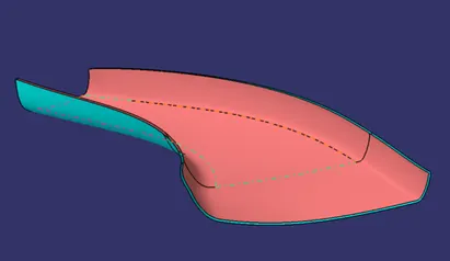
- Create boundary along Class A surface
- Use sweep command on it with 90deg angle to extend it towards B surface.
- This will be your C surface.
- Now join class A, B, C surfaces together to create a closed surface.
- Use closed body command to create a solid body.
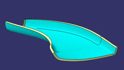
Doghouse Creation:
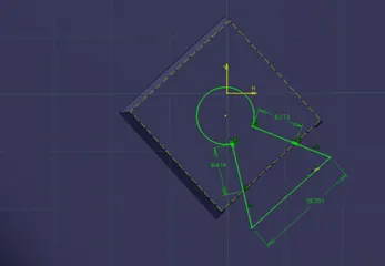
Ribs Creation:
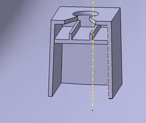
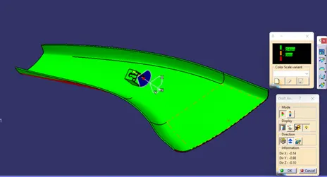
Draft Analysis:
- Before going to Draft Analysis go to customized view parameter >under mesh >check material and then click ok.
- Now for draft analyses go to insert » analysis » feature draft analysis.
- Use the compass to define the draft direction.
- In the colour scale change the draft angle to 0.4 Degree
- The component changes to green in indication of passing draft angle.
- Use running point to check the angle on the component.