Week 9 - Project - A pillar Design with Master Section
Report:
Objective:
Is to design the Plastic model to pass the feasibility check to avoid manufacturing error.
Tooling Axis:
The tooling axis is created to show the tooling direction which show the movement of the Mold and cavity & to exit the part without damaging the surface.
Draft Analysis:
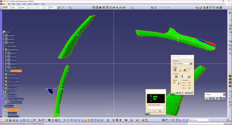
Draft Analysis for Class A Surface:
- Click the draft analysis command in analysis toolbar.
- Positioned the compass in the tooling axis.
- Activated the compass in draft analysis dialogue box.
- Again repositioned the compass in the tooling axis.
- Clicked the Class A surface.
- Here green color is given for surface clearing the draft angle of 2.9 and above.
- Here it clear in all surface. there is no defects in Class A surface.
Creating of Solid model:
Step 1:
Creating of Class B Surface:
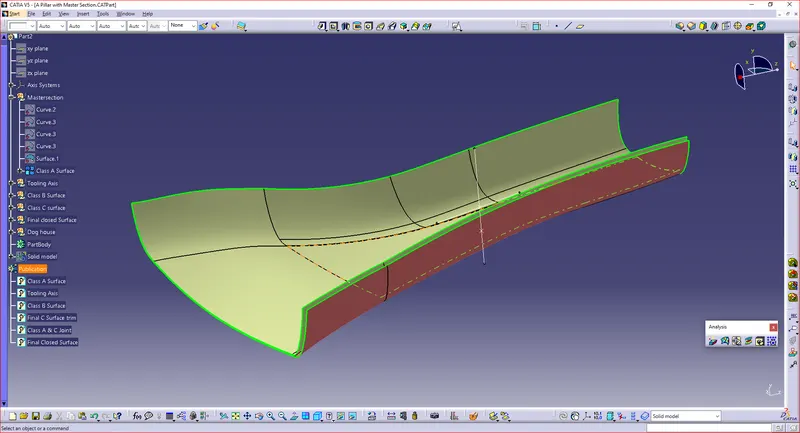
- Class B surface is created for the given offset value of 2.5mm.
Step 2:
Creating of Class C surface:
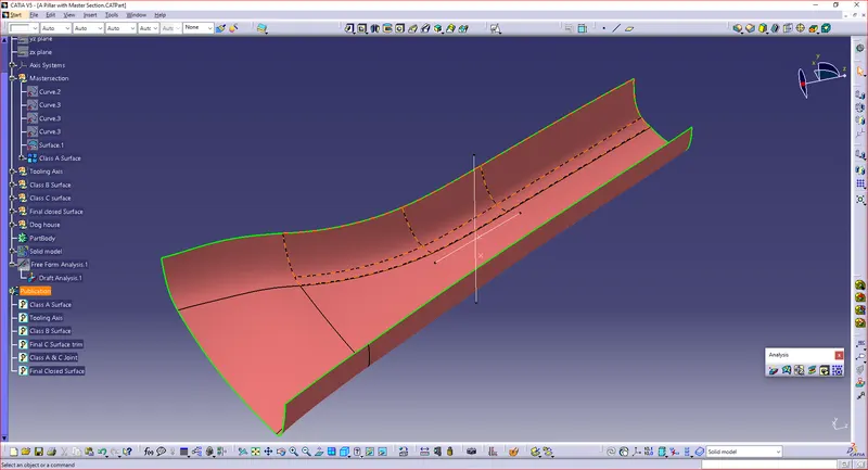
Class c surface is created between the Class A & B surface. This surface which act as connecting surface. Class C Surface is created from the Class A Surface using the sweep command with referance surface option. Creating the Class C surface plays major role which created According the draft angle to avoid the falling of parting line in the Class A Surface. The C surface is created outward from the Class A surface.
According to the class C surface the Class B surface is extrapolated to merge with the Class C surface.
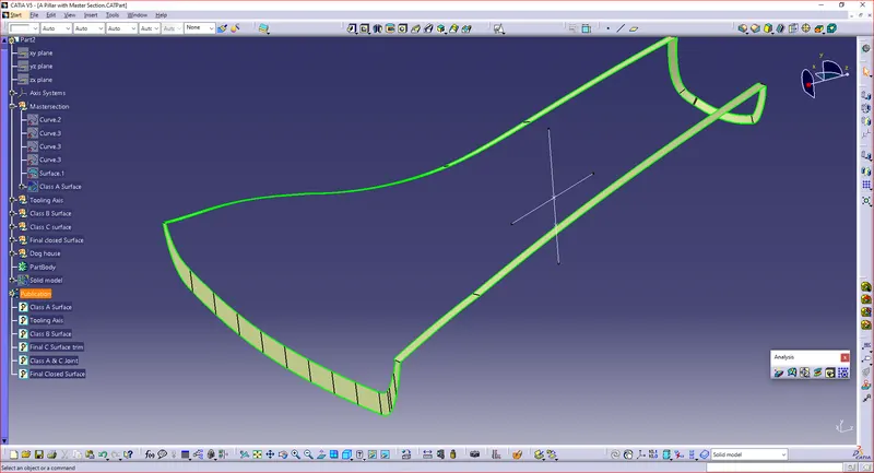
Class C surface draft angle is given about 3 degree
- Trim the class C surface to get the closed surface.
- Class C Surface is Joined to the Class A surface.
- Class A&C joint is trimmed with the Class B surface.
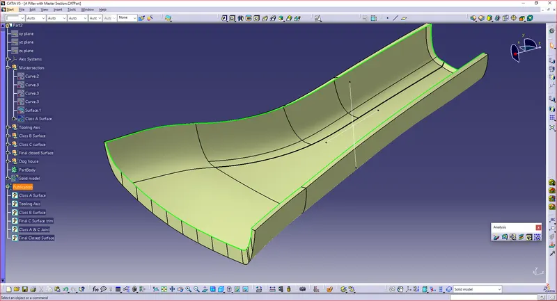
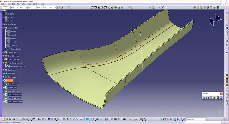
Verified the final surface trim has any boundary or nor.
By taking the boundary command and selecting the model.
It shows the notification as - the selected body is closed, it has no boundary.
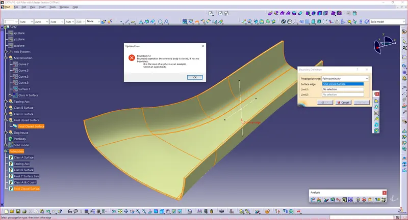
Step 3:
Creating of Solid model:
Switched to the part workbench.
Using Close surface command the surface model is converted into solid model.
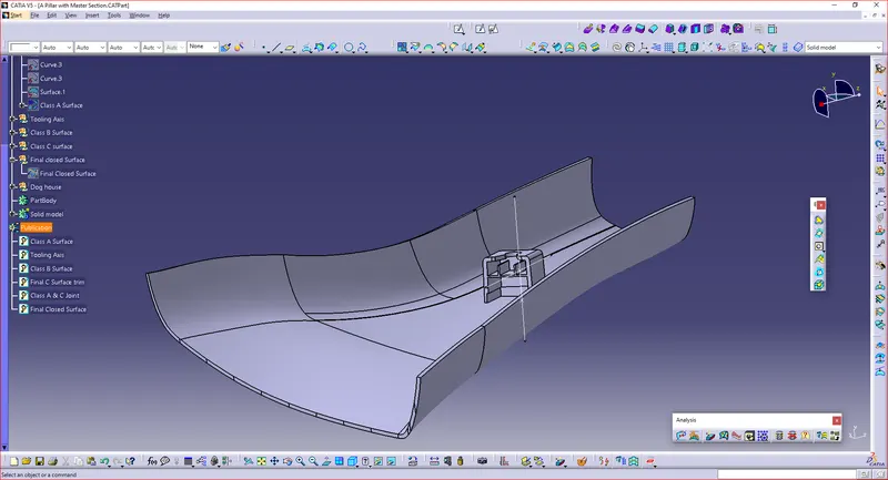
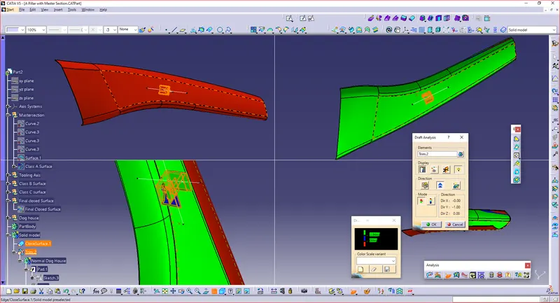
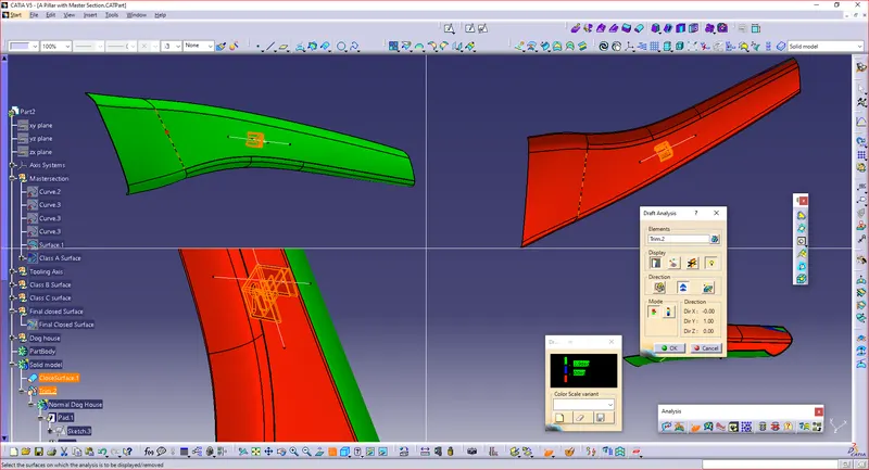
Draft analysis is performed for the final solid model:
- Click the draft analysis command in analysis toolbar.
- Positioned the compass in the tooling axis.
- Activated the compass in draft analysis dialogue box.
- Again repositioned the compass in the tooling axis.
- Clicked the solid model.
- Here green color is given for surface clearing the draft angle of 2.9 and above.
- Here it clear in all surface.
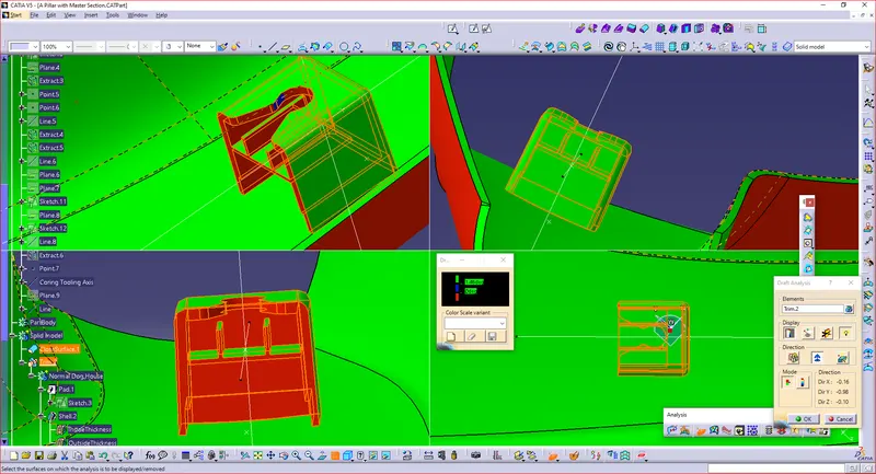
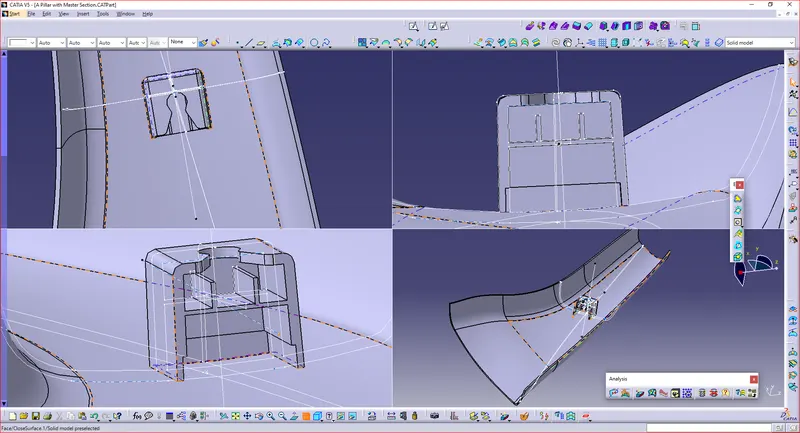
Creating of House from Master section:
- Using the Master section the dog house is created in the part workbench.
- Coring axis is created and draft analysis is performed.