Week 8 - Challenge 3 - Coin Holder Design
Report:
Objective:
Is to design the Plastic model to pass the feasibility check to avoid the manufacturing error.
Tooling Axis:
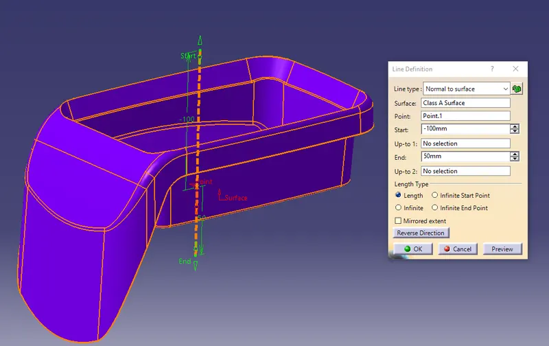
Tooling axis is create to show the tooling direction which show the movement of the Mold and cavity & to exit the part without damaging the surface.
Created the tooling axis on normal to surface.
Draft Analysis:
The Draft Analysis allows the user to easily analyze a part for proper draft angle. A Draft Angle say the amount of taper for molded or cast parts perpendicular to the parting line.
At first draft anaylsis is performed to the given Class A Surface to check the draft angle.
Step 1:
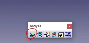
Click the Draft Analysis in the Analysis tool bar.
Step 2:
Positioning the Compass in tooling axis:
Placed the Compass in the tooling axis and Activated the compass in the draft analysis box and reposition the compass.
Selected the Class A Surface.
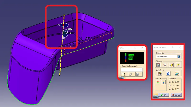
Step 3:
Showing the color difference for draft analysis:
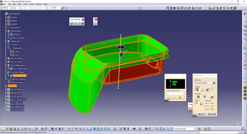
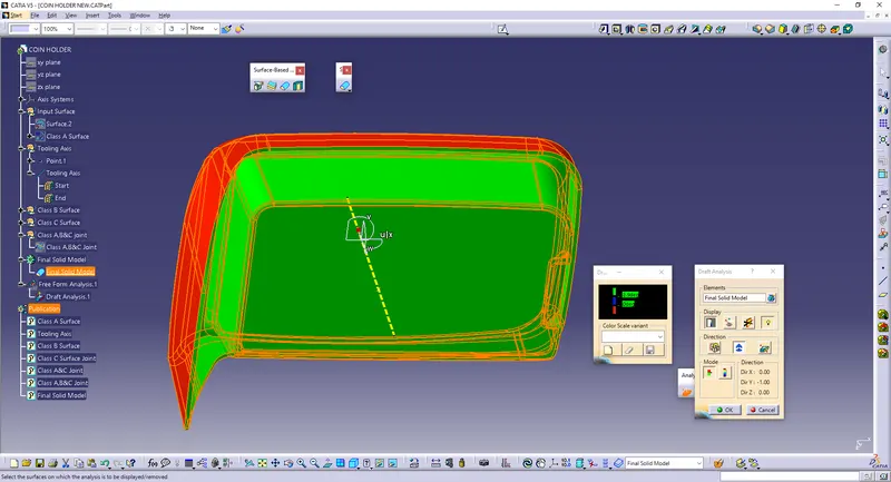
After selecting the surface it changes the color into green. It show that the Class A surface has perfect draft angle. If it show the Blue color try to create the tooling axis in normal to surface.
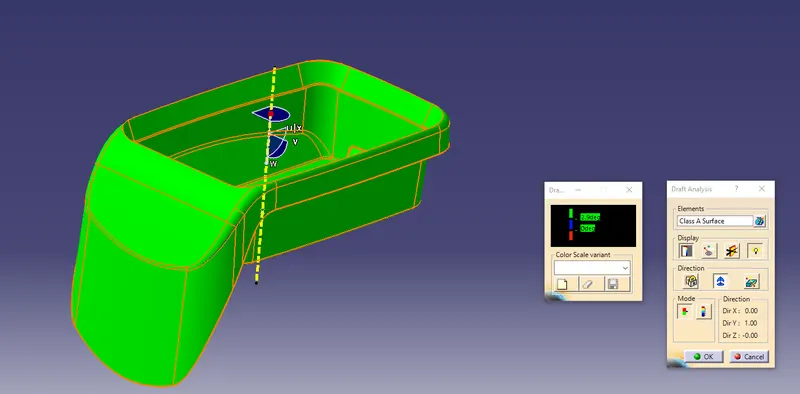
This how it will show the color changes.
Step 4:
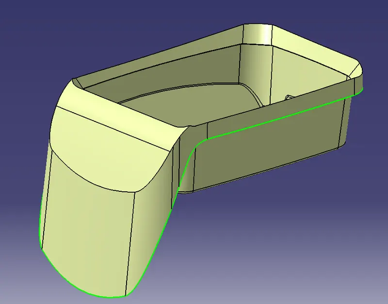
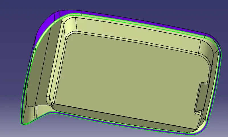
Creating Class B Surface:
After draft anaylsis, Class B surface is created for given offset vaule 2.5mm
Step 5:
Creating Class C Surface:
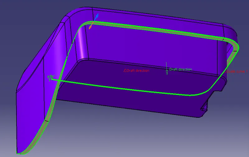
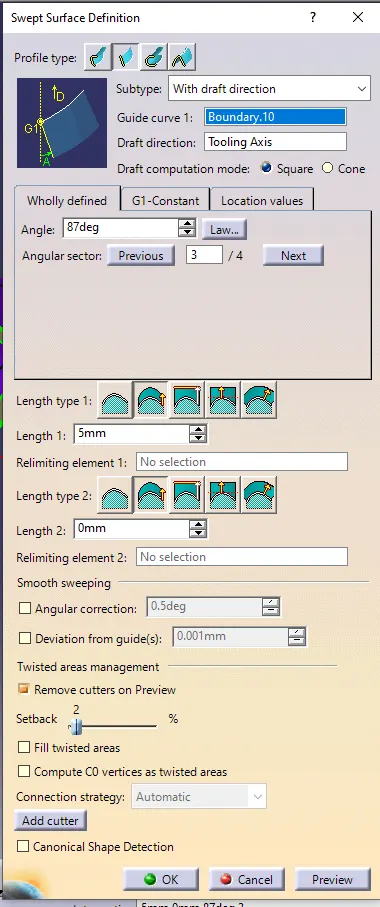
Class C surface is created by doing the Sweep command from the class A surface along the draft direction option. By giving the draft angle as 3 degree outward from the A surface. By giving the draft angle as 3 degree so the parting line will not occur in the Class A surface.
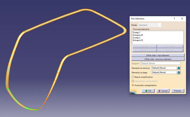
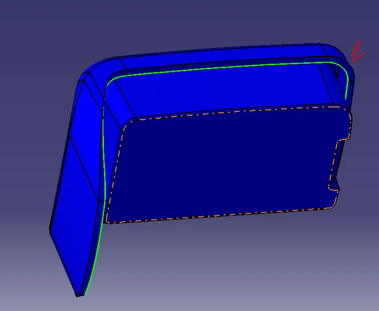
Extrapolated the C Surface and Trimed. Then the Class C and Class A surface is joined using the trim command.
Step 6:
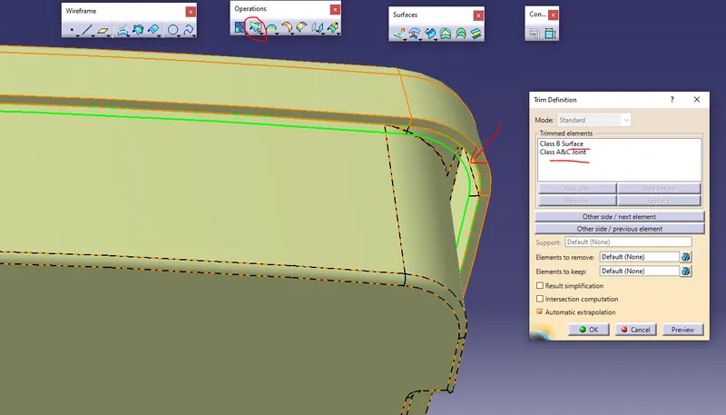
Trimming the Class A&B joint with the Class B surface:
Joined A&C Surface is trimmed with the Class B surface. It is will be the Final Trim.
Step 7:
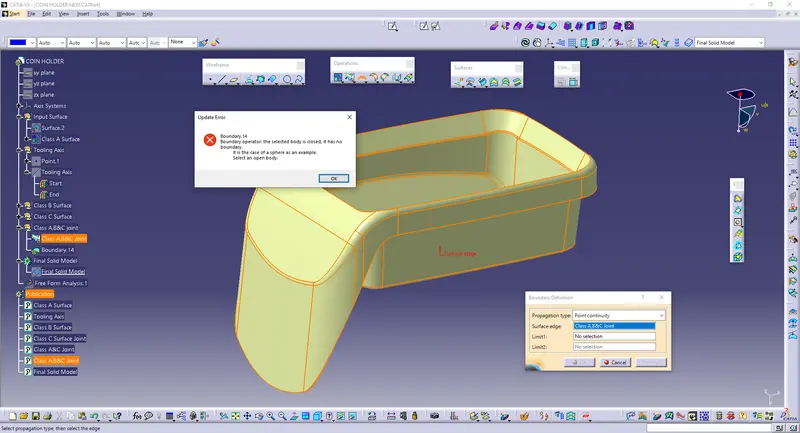
Checking if the trimmed surface using Boundary command:
Closed Surface is created. And final checking if the close surface has any gap or open surface. Taken boundary command to the closed body. It shows that (it has no boundary).
Step 8:
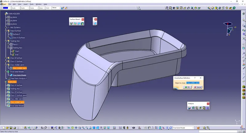
Creating the Solid Body:
Creating the Switched to the part workbench to create the solid body by using the close surface command in surface based feature.
Step 9:
Draft anaylsis for Final solid model:
Placed the Compass in the tooling axis and Activated the compass in the draft analysis box and reposition the compass.
Selected the Solid model.
Showing the color difference in draft analysis:
After selecting the Solid model it changes the color into green. It show that the Class A surface has perfect draft angle. It clearing the Draft angle, for Class A,B&C surface.