Week 9 - Project - A pillar Design with Master Section
A pillar Design with Master Section
Aim
To design the A-pillar with a master section considering the design rules.
Objective
To Design a Door handle and attach some engineering features on the B side of the component in CATIA V5 using the given Class A surface and design parameters.
Input data
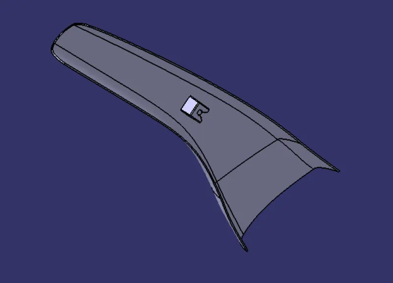
We use class-A-surface and master section as input data.
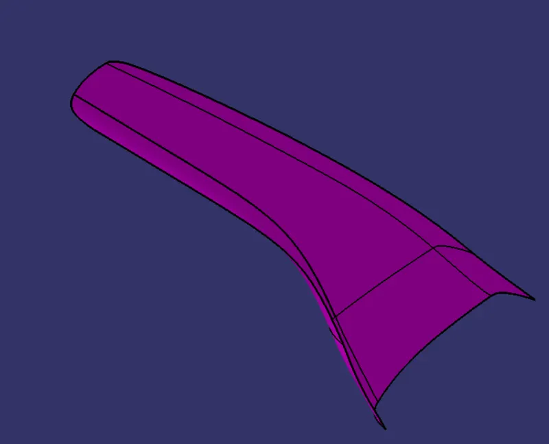
A surface
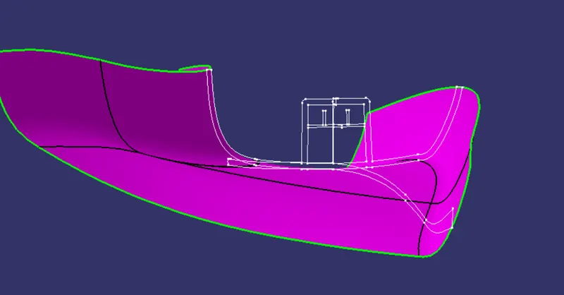
master section
Tooling direction
Tooling direction in which 2 halves of the mold get separated against each other. for this model am going to use the bisecting method because my tooling direction is Y axis and i have a master section at X axis so , am create two lines at the two parallel sides of the master section and draw a line by using point to point command and create the main tool axis by using bisecting line command that is my main tooling direction.
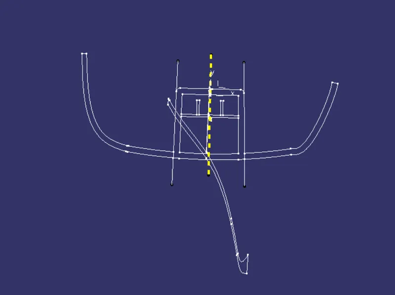
Draft Analysis Report of A surface
My tooling axis clears the minimum draft angle of 3 Degree so now i can proceed further option( You can also use normal to face option to get a tooling direction that's also works here)
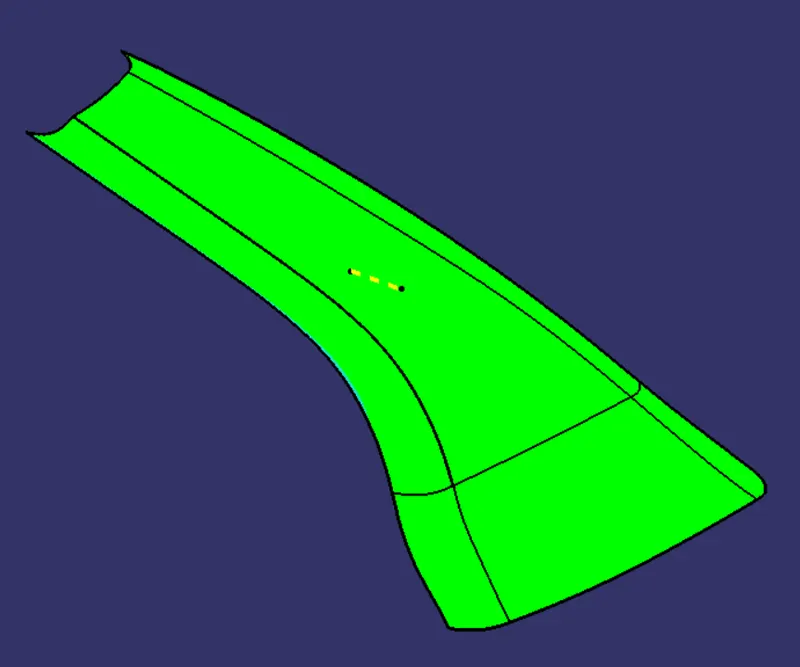
B-Surface creation
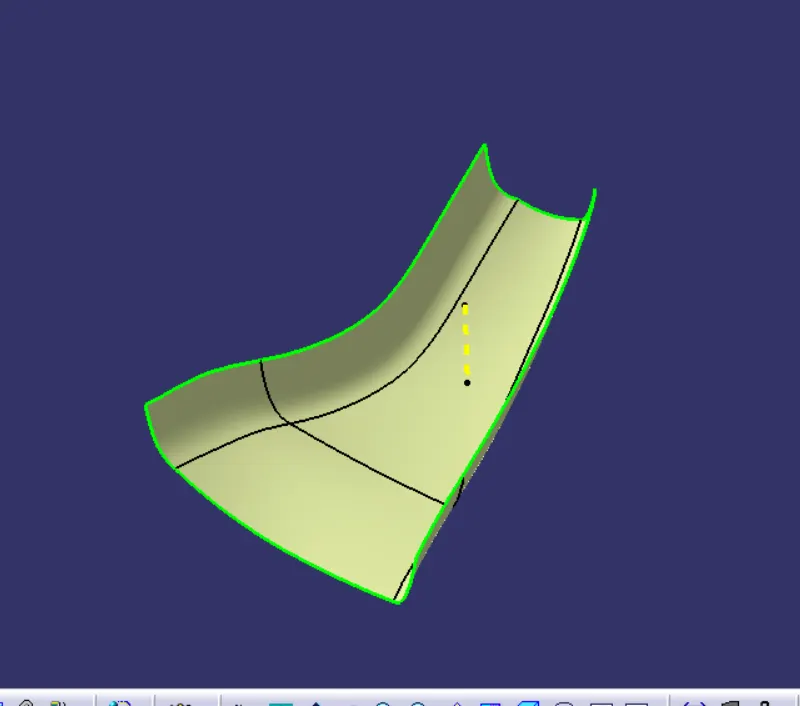
As usual B surface is created using the standard procedure by extract, , extrapolate, join, Trim, split, and offset ,multiple extract, multi section surface commands. The B-surface is created parallel to the A-surface
thickness of the A pillar is 2.5 mm i get this value form master section so we need to offset the A surfae 2.5mm inward and do a patch work.
C-Surface creation
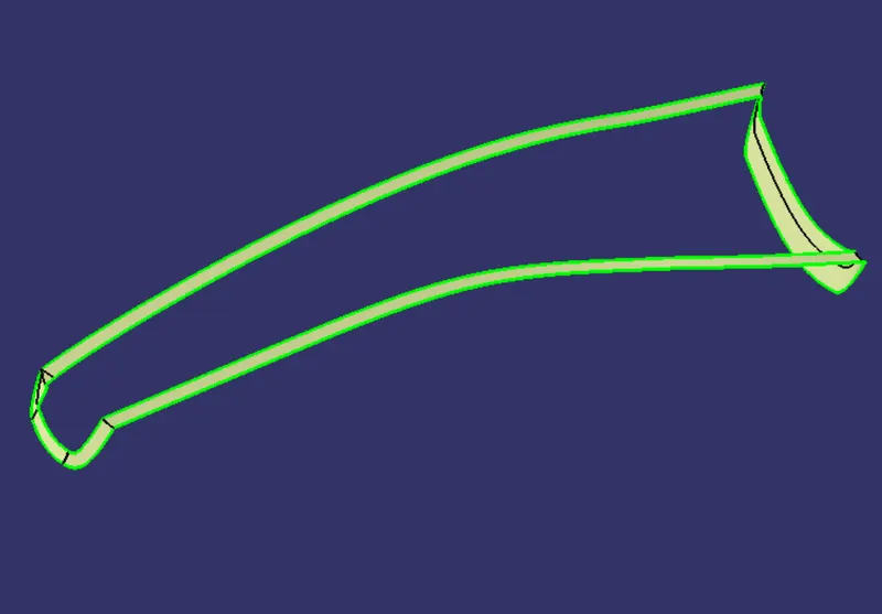
Class C surface for this component is created using the sweep command. All the ends of the component surface were facing parallel, so the C surface will create perpendicular to B surface.
To create a C-surface we need to extract the boundary of the A surface by using the Boundary(point continuity )command then create a swept it is perpendicular to the class-A-Surface outer edge
Converting into the solid model
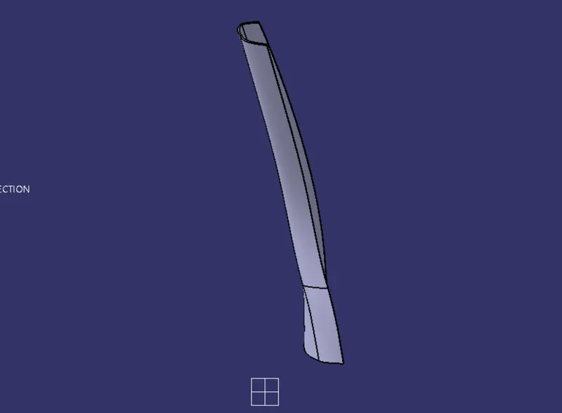
Once all surfaces are created Class A, B, and C surfaces are joined together to get the final closed volume. The closed volume is then converted into a solid body using the closed volume command in the part design workbench
Creating Dog house
What is Dog house?
Dog house is an engineering feature used in the plastic trim design. Dog houses are used as supporting feature. Sometimes other engineering features like snaps; locators etc. are mounded on them to increase their strength.
here we can easily create the dog house because we already have a master section as input data .
- first create one positioned sketch at ZX plane and use the projecting elemet to extract the master section and isolate it the reason why we need to give isolate means we dont want to disturb the master section data we make any kind of modifications regarding douse do it in a isolated sketch.
- Then use pad opearation to make this as a solid feature
- Follow the same procedure for inside ribs also
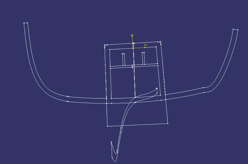
- After Pad the sketch we need to give shell by 2mm as wall thickness and extrude the ribs aslo
- Then give a draft of 0.5 degree to all the inside and outside faces of the dog house
- Then create C and B Section on Dog house at 40% of the wall thickness and the height of 3-6mm
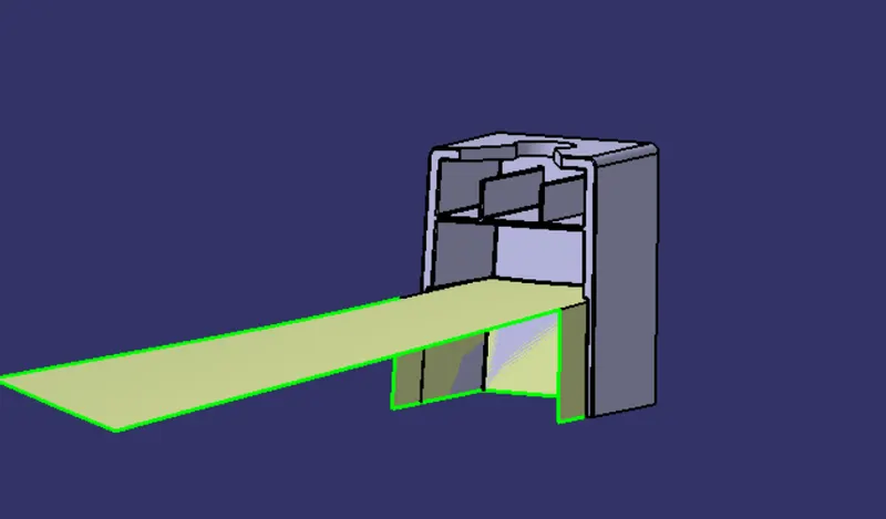
- And finaly use union trim to remove the dog house portion which is comes outside from the A-pillar outer walls after that we get A-pilar and dog house in one single body
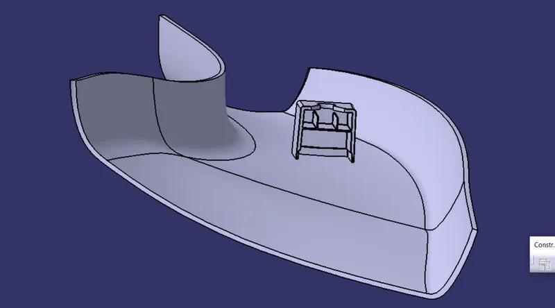
Features used
- Extract
- Offset
- Trim
- Untrim
- Split
- Swept
- Fillet
- Multiple extract
- Join
- Extrapolate
- Draft
Feature Tree
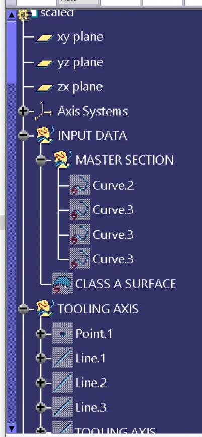
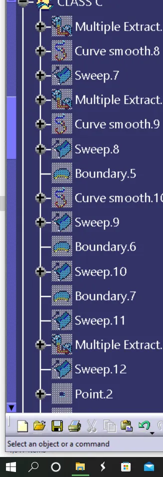
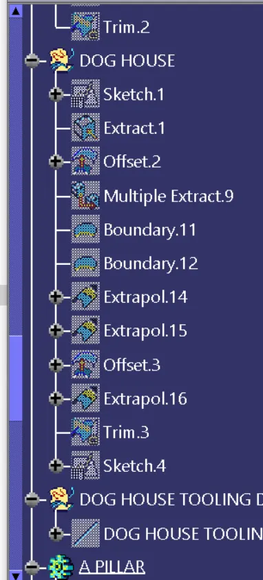
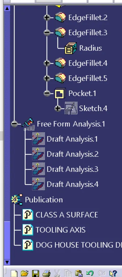
Different views of the model
Front view
Right view
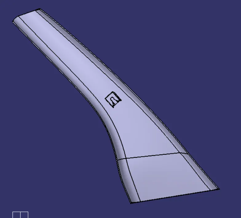
Top view
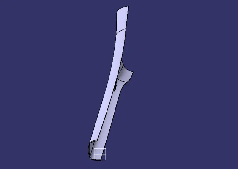
Isometric view
Draft Analysis
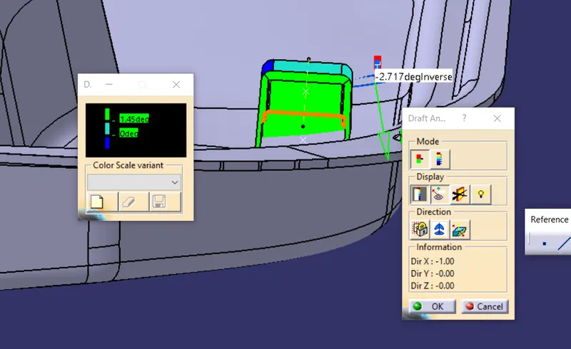
The Draft Analysis allows the user to easily analyze a part for a proper draft angle and check to the manufacturability of the component. here we need to do two draft analysis one for the A-pillar and another one for the dog house becuse both tolling directions was different the dog house was cleared inside the core side by side core or lifter and one more thin is minimum draft angle for A-pillar is 3-0 Degree and for Dog house 1.45-0.5
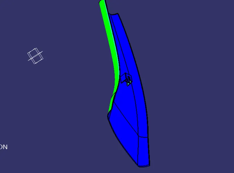
left side wall showed in a 0 degree we don't worry about it its cleared by the Main tooling axis
Conclusion
I have successfully completed the A-pillar design with master section challenge by using CATIA V5