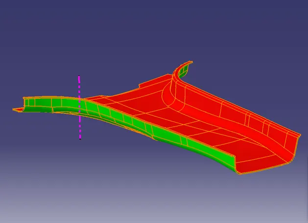
Car Pillar Design
Aim: To design the B-Pillar using the given Master sections.
INTRODUCTION:-
MASTER SECTION: Master sections development takes place during feasibility check and concept validation stages of the product life cycle. These are typically the guides for design requirements and which decides the component packaging after the development of the concept design, i.e class A surfaces.
Master section helps us to decide the feasibility of the concept design, the clearances, the packaging and the fixation strategy of a component before converting the concept design into a solid 3D engineering design.
During the period of vehicle concept design the evaluation of the master section performance depends mainly on the reference vehicle data and experience of structure design engineer.
Theory:-
Tooling Axis - Tooling Axis is the direction in which the component will be ejecting after the molding process is completed. The rules of selecting an optimum direction of tooling axis for any particular component is as follows :-
- The direction of the tooling axis should be clearing the maximum number of portions of the component once the molding process is completed.
- The direction of the tooling axis should be selected such that the number of side cores required should be minimum, as inserting side cores causes a rise in production cost.
Drafting - Draft is the inclination given to any particular plastic component’s cavity walls in order to achieve easy ejection, once the process is completed.
- Consider that the draft angle between the plastic component and the core is zero.
- When the molten plastic inside the cavity cools, it sticks to the walls of the core.
- During such zero draft condition, the ejection of the plastic component causes friction between them which might bring damage to both the core and the component.
- This damage further leads to inefficiency in the production & also affects the product’s surface finish.
- Hence, a minimum of ½ to 1 deg draft is provided to help in releasing the component.
- However 3 deg draft is widely accepted as a norm in the industry.
Prerequisites before creating the tooling axis and performing draft analysis-
- Ensure that the Class A surface imported should be a single surface.
- This can be checked using the Boundary tool in the Operation Toolbar.
- If the surfaces are disassembled, join them using Join command which is also found in the Operation toolbar.
Creating any component from Class A Surface ( Overview ) -
- Decide a suitable tooling axis direction and create the Tooling Axis.
- Perform Draft analysis for analyzing whether the drafts on the component follow the industry standards.
- Create another surface ( B Surface ) offset to the Class-A Surface. The offset distance should be equal to the thickness of the component.
- Create a C- Surface ‘Sweeping’ the boundary of Class-A -Surface along the Tooling Axis.
- Trim Class- A surface with B-Surface and C Surface to create a closed surface.
- Finally create the solid part from this surface to obtain the desired component.
Pillars:
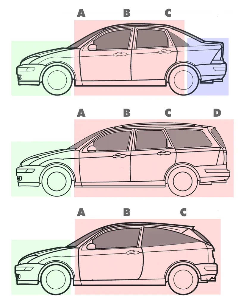
Pillars are vertical supports or nearly vertical supports provided to the car’s window area. They are designated to be -A,B and C. As per the alphabetical order, A-Pillar is the front support, B-pillar is the middle support and C-Pillar is the Rear support. In larger cars they also have a D-Pillar for the rear most support.
DESIGNING METHODOLOGY:
IMPROVING THE CLASS A SURFACE
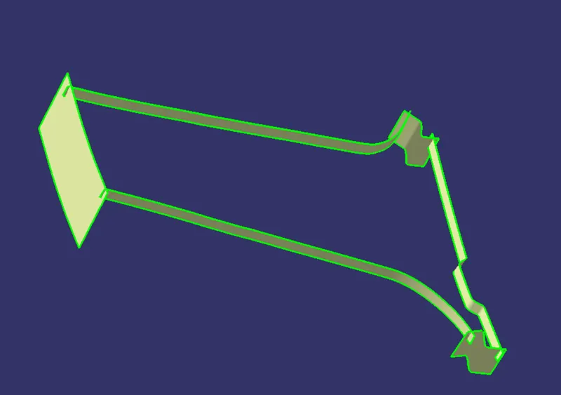
The given class A surface is not a proper surface because it is lacking the side flanges so first thing that we have to do is to create the flanges on both the sides of the class A surface.
For creating flanges we will first extract the side edges of A surface and the surfaces touching these edges.
Finally we'll apply the sweep command using the "with reference to the surface" option and join the resulting edges with A surface using trim command.
Make sure that the resulting flanges are properly oriented according to the master section.
CLASS B SURFACE CREATION
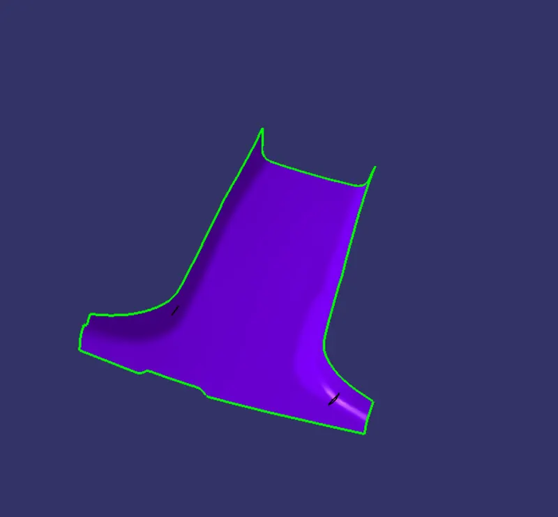
We need a thickness of 2.5mm for the A PILLAR so in order to create the class B surface we'll give an offset value of 2.5 mm to improvised class A surface.
After applying the offset command we'll see some of the patches of the resulting surface are not generating so we have to recreate those patches by using multi-section surface command.
On joining the recreated patches with the offseted surface we'll get the class B surface
CLASS C SURFACE CREATION
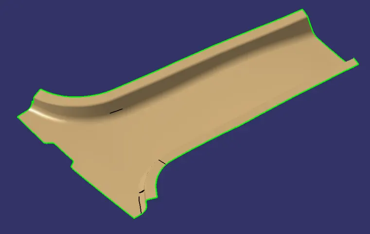
Extract the side edges, front edges and rear edges of the improved class A surface and use sweep command using "with refrence to draft" option and make the draft angle equal to 3 degrees.
For the rest of the edges use multi-section surfaces command to make surfaces inline with the major surfaces created through sweep.
Join all the surfaces together using join command.
SOLID BODY CREATION OF THE A PILLAR
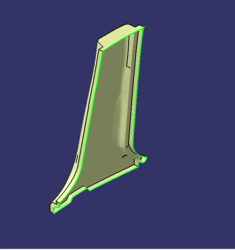
Using the Trim command join the class A surface with class C surface.
Trim the resulting Trimmed surface with class C surface.
The resulting trim we'll get is the closed shell body of A pillar.
Finally use closed surface command in the part design workbench which would lead the shell body into a part body.
Draft Analysis
The Draft Analysis command enables you to detect if the part you drafted will be easily removed. This type of analysis is performed based on color ranges identifying zones on the analyzed element where the deviation from the draft direction at any point, corresponds to specified values.
Draft angles are very important in thermoforming product design. If the product is formed onto a female or negative mold, it shrinks away from the mold sidewalls. As a result, true female or negative products can be thermoformed with vertical walls having zero draft angles. Parts Cannot be ejected from the tool if it is at 90 degree surface.for the reason,A small Draft angle is to be provide for each and every surface s of the Component in order to easy removal of component from the moulds without any defects.Draft is the angle in which the part is tapered to aloow it to release.Most of the part require minimum 1/2 degree to 1 degree however 3 degrees are widely accepeted in plastic component design.Draft Analysis is the technique used to analise weather our designed product are manufacturable with required conditions or not.