Design of B pillar for a vehicle
AIM
The aim of the project is to create a solid body of the B pillar from the input provided as the class A surface and attach attachment features for fixing the component at appropriate position with the main component following the OEM design standards using CATIA V5 software.
INTRODUCTION
The B pillar is the component which is present in between the front and rear door of an vehicle that connects with the body with the roof.
The steps that are involved in making the above project is mentioned below:
1. Importing the class A surface of the B pillar.
2. Determining the main tooling axis for the component.
3. Designing class B surface for the B pillar
4. Designing class C surface in between the class A and class B surface.
5. Creating solid closed body from the closed surface.
6. Attaching dog house, locators and ribs on the class B surface.
7. Determining the lifter axis for the tooling of Dog house.
8. Draft Analysis for the Class B surface and the Dog House.
PROCEDURE :
1. Importing the class A surface.
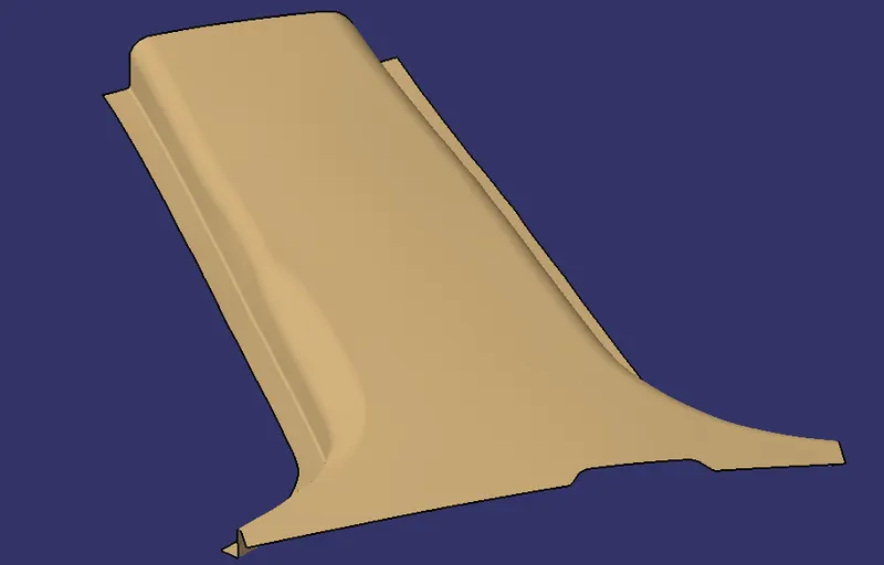
The first step in doing this project is to bring the class A surface of the B pillar for making other designs.
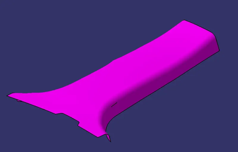
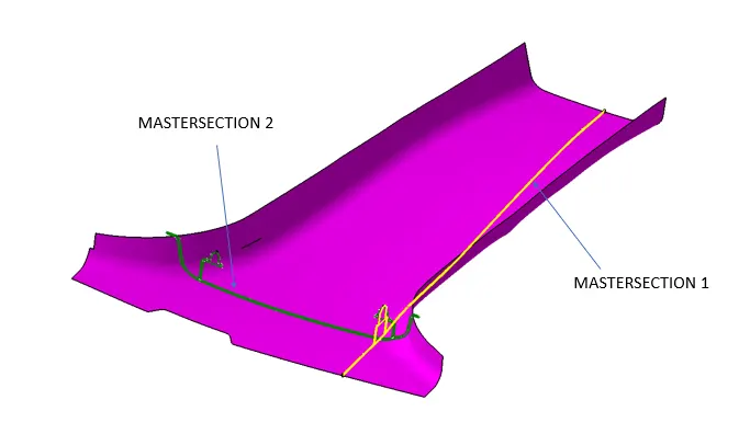
Along with the class A, master sections are also provided as input to design the various attachment features on the class B surface.
2. Determining the main tooling axis.
The tooling axis plays an important role in determining the safe extraction of the component after the moulding process. This also helps in giving the direction in which the components have to be drafted.
For the B pillar the tooling axis is determined by taking references from the master section and then using line bisecting line feature for creating tooling axis in perpendicular direction.
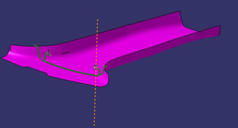
To check if the tooling axis is in the correct direction draft analysis is performed on the class A surface.
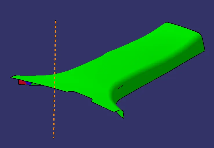
From the above image we can observe that the tooling axis is in correct direction and other surfaces can now be designed with respect to the class A surface and the tooling axis.
Flanges are designed on the sides for fixing the B pillar with the front and the rear door.
3. Class B surface
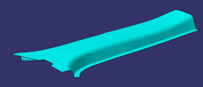
The class B surface is created by analysing the class A surface and then using the offset feature to create a copy of the same body at a distance of 2 mm from the class A surface.
The patches on the class B surface are rectified by working on each patch by extracting the surrounding surfaces and then joining them with the rest of the body.
4. Class C surface
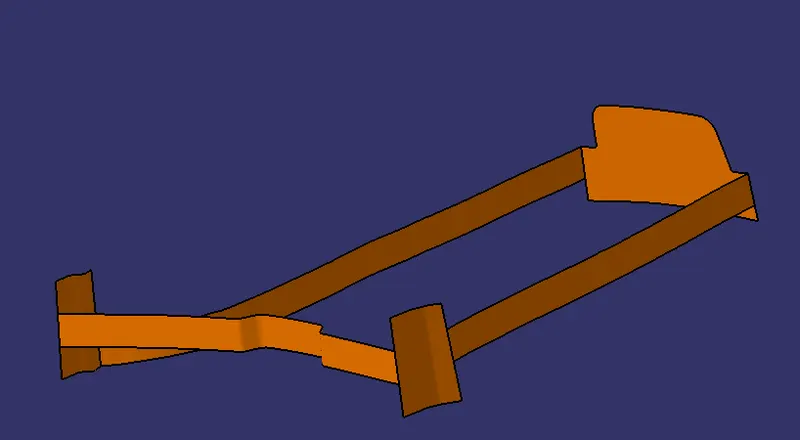
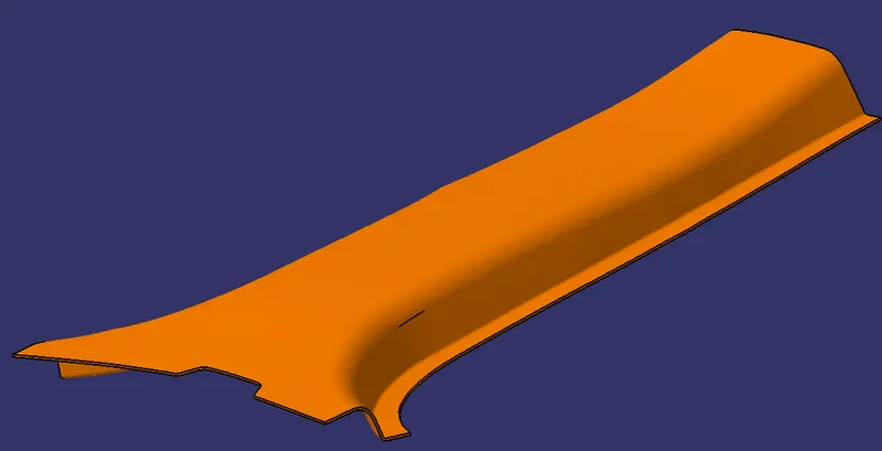
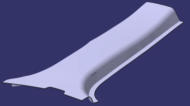
The class C surface is present in between the class A and class B surface to connect them with each other and then closed the class A, class B and class C surfaces together to form closed surface body.
Below image shows the class C surface and then attachment with the class A and class B surfaces.
5. Closed solid body
When class A, class B and class C surfaces are designed and joined together using trim and join commands it is ensured whether the surfaces have any gaps using the boundary command. After ensuring that the surfaces are closed with no gaps it is converted into solid body with the help of Closed surface feature in part work bench.
6. Attachment Features
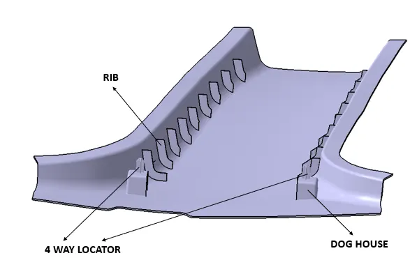
Attachment features are placed on the class B surface for fixing the component at appropriate position with the main body and also providing strength to the component.
The different attachment features that are placed on the class B surface of the B pillar are:
1. 4 way Locators
2. Dog House
3. Ribs
1. 4 way Locators
The 4 way locators are used for easy fixation of the B pillar with the main body of the vehicle.
2. Dog House
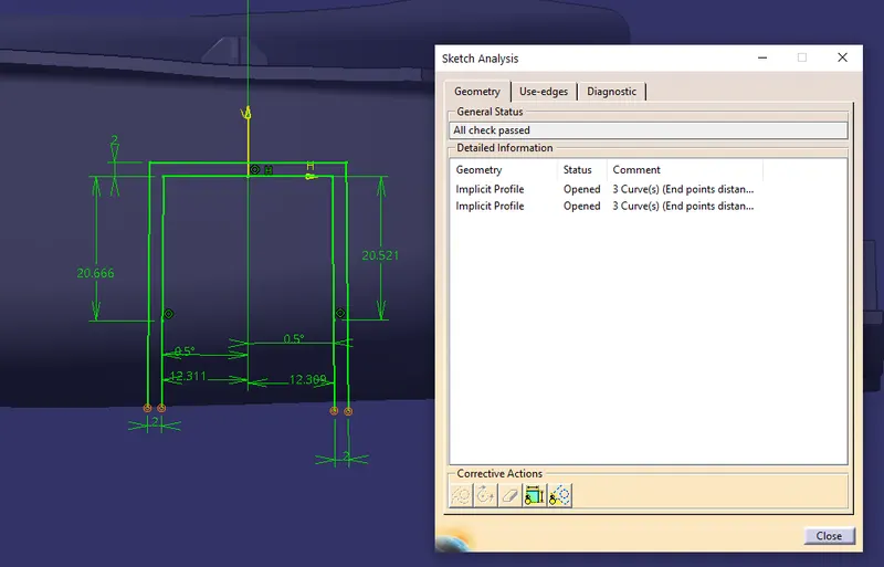
The Dog house for the B pillar is used to avoid sink marks on the class A surface.
Dog House Sketch
3. Ribs
The Ribs are designed on the class B surface to provide strength to the component to avoid breaking of the component under high stress.
6. DETERMINING LIFTER AXIS FOR THE DOG HOUSE
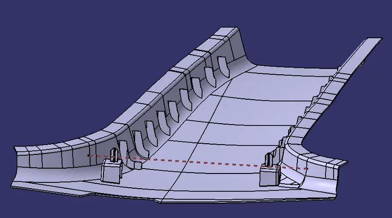
As the Dog House has undercuts, this cannot be designed along the main tooling axis, in order to make these components Sliders are used which comes from the Lifter axis direction.
Below images shows the direction of the Lifter Axis.
7. DRAFT ANALYSIS
Draft Analysis is performed to check whether the component can be easily tooled along the tooling axis.
The different draft analysis performed on the component are:
1. Along the class A surface.
2. Along the class B surface with the attachment features.
3. Along the lifter axis to check the draft analysis inside the dog house.
1. Draft Analysis for the Class A surface
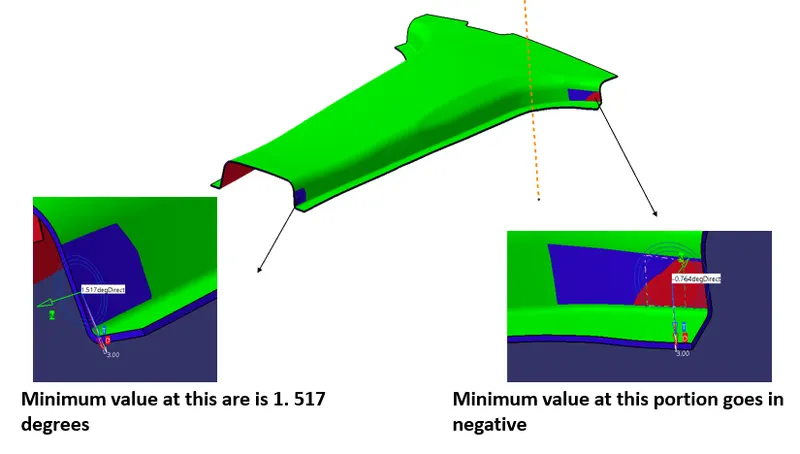
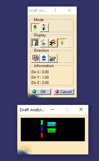
The draft analysis on the class A surface along the main tooling axis shows that all the areas are with minimum draft of 3 degrees except the areas that are highlighted above. This observation will be sent to the class A team who will look into this and rectify it.
2. Draft analysis for Class B surface
The draft analysis on the class B side is performed to check whether the attachment features like dog house, ribs and 4 way locators can be easily tooled along the tooling direction or not. For this purpose, a draft of minimum 0.5 degree is provided for each attachment feature according to the standards followed by the industry.
Below image shows the draft analysis :
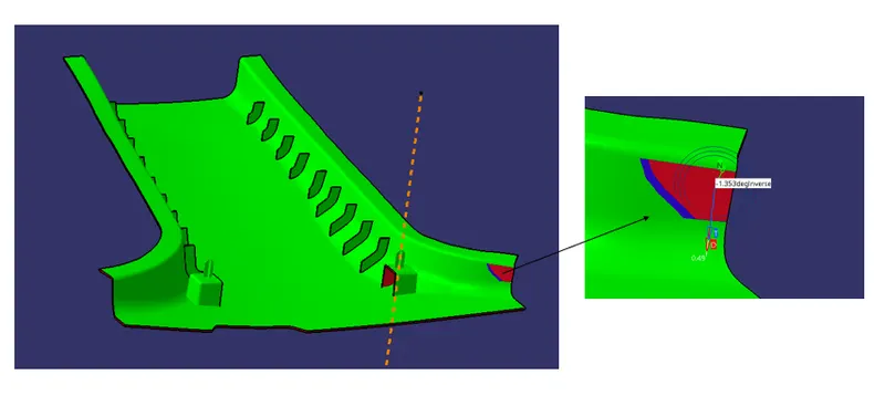
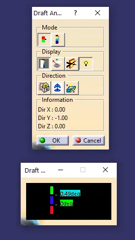
From the draft analysis we can observe that all the areas have minimum 0.49 degrees of draft which can be manufactured easily according to the industry standards. The portion in red will be taken as observation and will be sent to the class A styling team to rectify the specified portion.
3. Draft Analysis for Lifter
As the inside portion of the Dog House cannot be tooled along the main tooling axis so in order to make the desired inside shape of the dog house a lifter will be used, draft analysis for the lifter tooling axis is shown below:
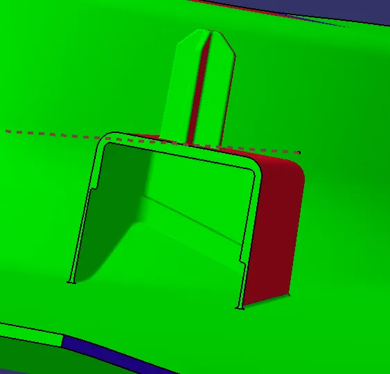
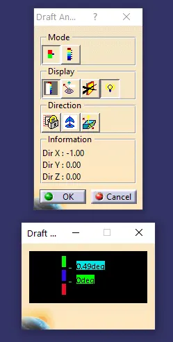
From the analysis we can observe that the inside portion of the dog house has minimum 0.49 degree draft and above which means that it can be tooled easily along the lifter tooling axis.
Colour Indication:
1. Green: It shows the angle above 3 or 0.49 degrees which is safe for making the component.
2. Blue: It shows that the region has an angle between 0 to 3 degree or 0 to 0.49 degree.
3. Red: It indicates that the region is below 0 degrees and unsafe for manufacturing. Such instances will be notified to the class A styling team to make corrections at the specified regions.
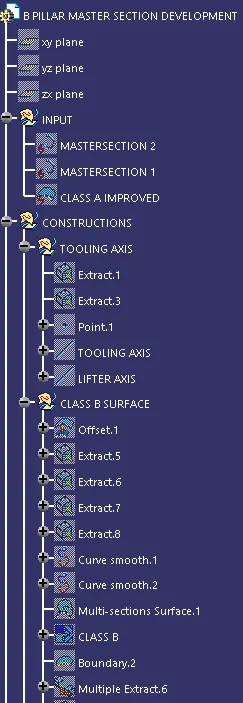
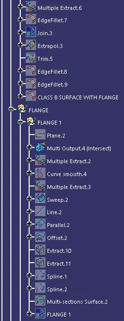
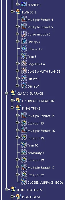
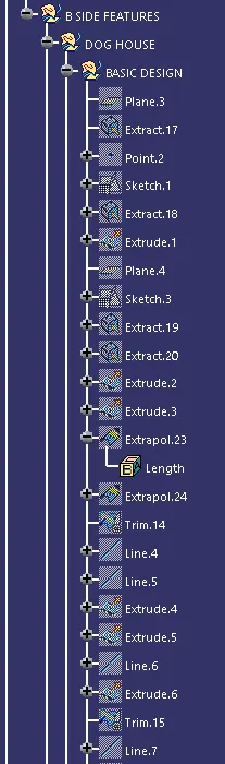
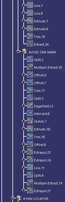
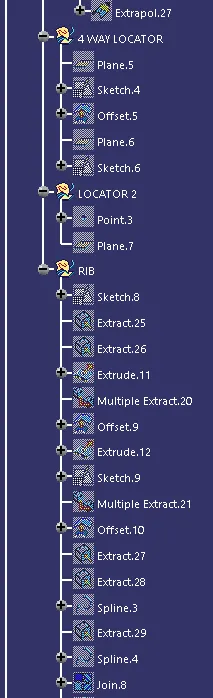
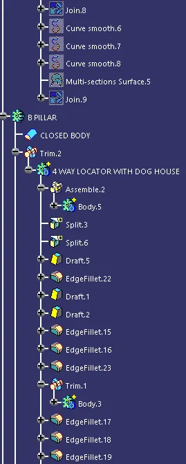
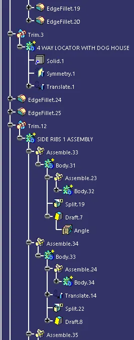
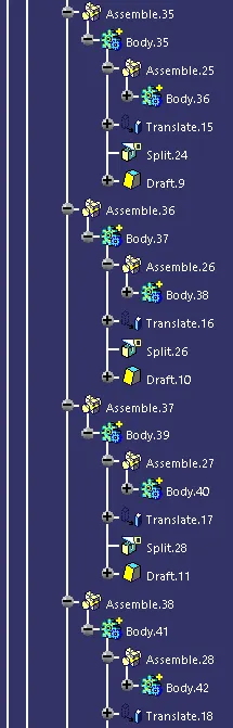
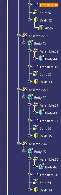
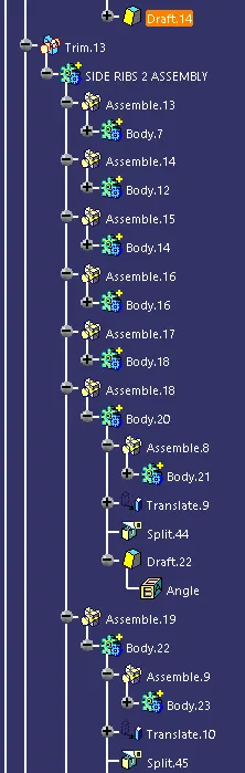
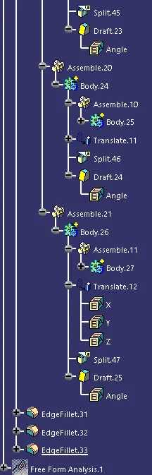
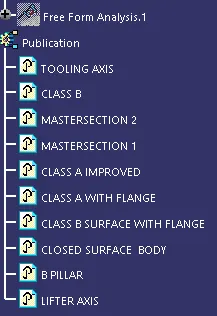
Detailed Tree Structure
The below images shows the features and the commands that were used to make the B pillar:
CONCLUSION
1. Class A, Class B and Class C surfaces were designed as per industry standards providing draft at required portions and converted into solid body.
2. The tooling axis and the lifter axis were determined for the component for safely manufacturing the component.
3. Attachment features were made on the class B surface as per the master section provided as input.
4. Draft analysis was performed at the required region to check whether the component can be tooled along the tooling direction for safely manufacturing the component.