Week 9: Project 1 - Surface preparation and Boundary Flagging (PFI)
Aim: To perform the boundary flagging and surface preparation for a 4-stroke IC engine and run with a no-hydro simulation.
Theory:
The most widely produced internal combustion engines were of the Port Fuel Injected (PFI) design, where the fuel is sprayed into the intake ports to mix with incoming air. A four-stroke (also four-cycle) engine is an IC engine in which the piston completes four separate strokes while turning the crankshaft. A stroke refers to the full travel of the piston along with the cylinder, in either direction. The four separate strokes are termed as
Intake, Compression, Combustion, and Exhaust.
The 4-stroke PFI (Port fuel injection) model is given to perform the no- hydro simulation it means that there will be no reaction and how the mesh was done & the movement of parts in the engine is working that will be checked.
Surface Preparation: Export the geometry and run a diagnosis on the IC engine there are several errors or problems were found, like intersections, open edges, overlapping, nonmanifolds, and normal orientations, etc.
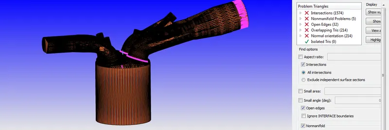
Open Edges: These are the holes in the surfaces or missing triangles on the surface. To avoid this click on repair > patch > select free edge loop in patch options > By using open edge select Outline and click apply.

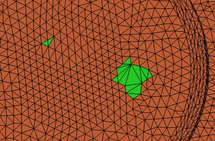
Non-manifold problems: The triangles created in converge to define the geometry have 2 edges emerge from the given vertex. When more than 2 edges emerge from the same vertex then a nonmanifold error arises.
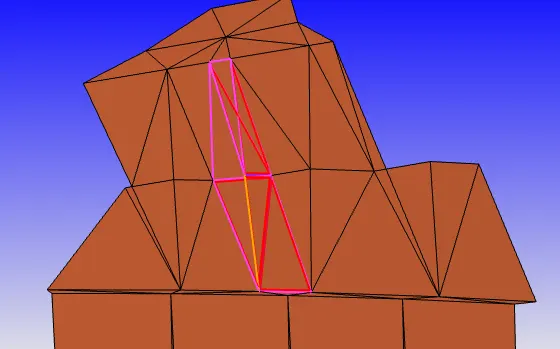
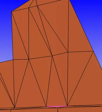
Interactions: Interactions occur where two or more triangles intersect with each other. On closer inspection, it was found that the intake valves had been pushed open so much during modeling of the IC Engine that their triangles intersected with the triangles of the cylinder head.
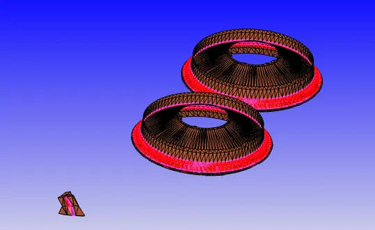
Overlapping tris: Overlapping tris means triangles overlapping one over another and the normal orientation belongs to the incorrect direction of the normal vector of the triangles.
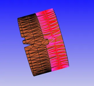
Boundary flagging: After completion of the surface modeling, flag boundaries according to their components.
Individual components:
Piston:
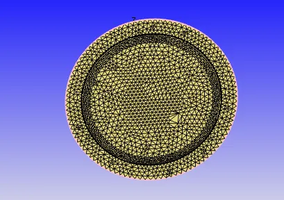
Cylinder head and liner:
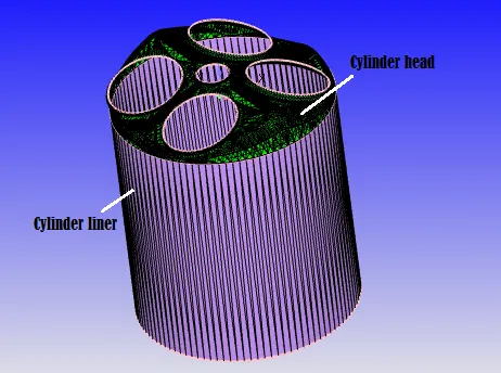
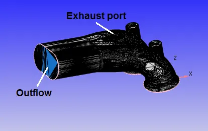
Exhaust port:
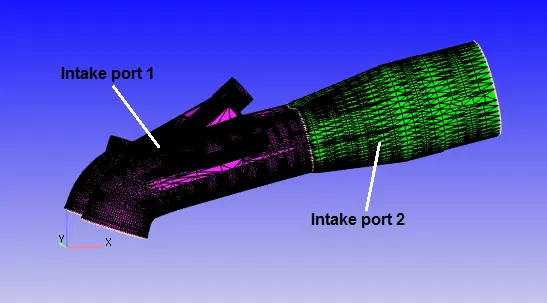
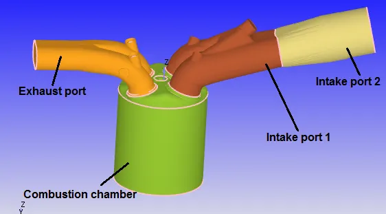
Intake port: The intake port near the combustion chamber region needs to be initialized with some amount of fuel because during the completion of a cycle there are some spray parcels that get leftover. Flagging the intake ports differently would allow us to create two separate regions. One region would be near the combustion chamber with initialized fuel and at a relatively higher temperature. The portion of the intake chamber away from the cylinder head would be kept at atmospheric conditions.
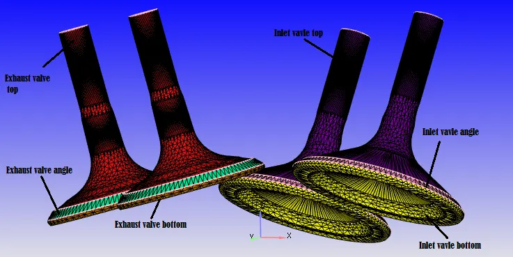
Intake and Exhaust valves: Here the valves were flagged into 3 different regions(valve top, angle, and bottom) because to make it easier to control events. Another reason for doing this because the disconnect triangles restrict the flow when they are created but then let the flow happen once opened. This is Converge’s way of enabling flow between these two regions. These triangles to be as straight as possible and need to be aligned with the normal of the valves. Not flagging the valves differently leads to the triangle being created above the angle boundaries. This would restrict the flow thus leading to the under-prediction of mass flow in the combustion chamber. By flagging the valves differently it can be made possible to provide an embedding in that region because when the valve opens it is near this angle region where maximum pressure drop and maximum velocity flow will occur. So for that reason, a concept known as minimum lift comes into play where the valve sits at this distance of min lift which is 0.2 mm. It is known that cell pairing takes place when the cut cell is 30% the size of the base cell. So by providing a boundary embedding with a cell size of 0.5mm can be created which is 40% the size of the base cell which in turn would avoid pairing. The disconnect triangles shown below are only for demonstration purposes. This is similar to how Converge creates the triangles during events.
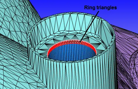
Ring tringles at the top of valves: Flag the ring triangles near the top surface of the valves to the exhaust port. This is a standard practice that needs to be followed because the valves open and close continuously during the operation of the engine. Not flagging these ring triangles to the exhaust or intake ports would lead to the stretching of the ports when the valves open and close that would lead to geometry distortions.
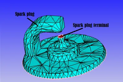
Spark plug:
After setting the regions to the boundaries, and group colour by regions.
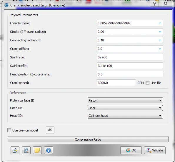
Case setup:
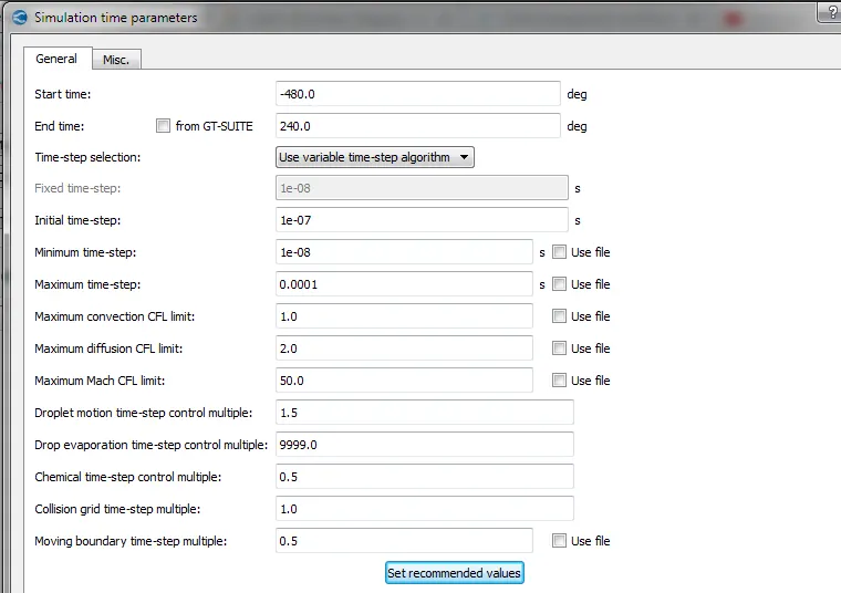
First set the IC engine simulation to the no-hydro mode to verify that the cleanup, boundary flagging, and initial setup was done properly.
Region and Events:
The operating conditions used inside each of the regions were as follows:
- Intake port - 1 (closer to combustion chamber)
- IC8H18 - 0.025508
- O2 - 0.20157
- N2 - 0.77292
- Temperature - 390 K
- Pressure - 1 bar
- Intake port - 2 (away from combustion chamber)
- Air
- Temperature - 370K
- Pressure - 1 bar
- Combustion Chamber
- Pressure - 1.85731 bar
- Temperature - 1360 K
- Stoichiometric composition
- Exhaust Region
-
- Temperature: 1360 K
- Pressure: 185731 bar
- Stoichiometric composition
Events:
| Type | Region A | Region B | Event by | Event |
| Cyclic | Combustion Chamber | Intake port 1 | Region | Valve |
| Cyclic | Combustion Chamber | Exhaust port | Region | Valve |
| Permanent | Intake port 1 | Intake port 2 | Region | Open |
Boundaries:
| Component Name |
Boundary Type |
Pressure Boundary Condition |
Velocity Boundary Condition |
Temperature Boundary Condition |
Species Boundary Condition |
Turbulent Kinetic Energy |
Turbulent Dissipation |
Region |
| Piston | Wall | NA | Translating/Moving with No-Slip |
Law of wall | NA | Zero Normal Gradient |
Wall Model |
Cylinder Region |
| Inflow | INFLOW | 101325 Pa |
Zero Normal Gradient |
Specified Value = 363 K | Air | Default | Default | Intake Port -2 |
| Liner | Wall | NA | Stationary/FIXED with Law of Wall |
Law of wall = 450 K | NA | Zero Normal Gradient |
Wall Model |
Cylinder Region |
| Cylinder Head |
Wall | NA | Stationary/FIXED with Law of Wall |
Law of wall = 450 K | NA | Zero Normal Gradient |
Wall Model |
Cylinder Region |
| Exhaust Port |
Wall | NA | Stationary/FIXED with Law of Wall |
Law of wall = 500 K | NA | Zero Normal Gradient |
Wall Model |
Exhaust Region |
| Outflow | OUTFLOW | 101325 Pa | Zero Normal Gradient |
Backflow Temp = 800K | Species BackFlow = CO2, H2O and N2 with mass fractions 0.192304, 0.088559, and 0.719137 |
Default | Default | Exhaust Region |
| Intake Port 2 |
Wall | NA | Stationary/FIXED with Law of Wall |
Law of wall= 425 K |
NA | Zero Normal Gradient |
Wall Model |
Intake Port -2 |
| Exhaust Valve Top |
Wall | NA | Translating/Moving with Law of Wall For Motion trajectory use file |
Law of wall= 525 K | NA | Zero Normal Gradient |
Wall Model |
Exhaust Region |
| Exhaust Valve Angle |
Wall | NA | Translating/Moving with Law of Wall For Motion trajectory use file |
Law of wall= 525 K | NA | Zero Normal Gradient |
Wall Model |
Exhaust Region |
| Exhaust Valve Bottom |
Wall | NA | Translating/Moving with Law of Wall For Motion trajectory use file |
Law of wall= 525 K | NA | Zero Normal Gradient |
Wall Model |
Cylinder Region |
| Intake Port 1 |
Wall | NA | Stationary/FIXED with Law of Wall |
Law of wall= 425 K | NA | Zero Normal Gradient | Wall Model |
Intake Port -1 |
| Intake Valve Bottom |
Wall | NA | Translating/Moving with Law of Wall For Motion trajectory use file |
Zero Normal Gradient |
NA | Zero Normal Gradient |
Wall Model |
Cylinder Region |
| Intake Valve Angle |
Wall | NA | Translating/Moving with Law of Wall For Motion trajectory use file |
Zero Normal Gradient |
NA | Zero Normal Gradient |
Wall Model |
Intake Port -1 |
| Intake Valve Top |
Wall | NA | Translating/Moving with NoSlip For Motion trajectory use file |
Zero Normal Gradient |
NA | Zero Normal Gradient |
Wall Model |
Intake Port -1 |
| Spark Plug |
Wall | NA | Stationary/FIXED with Law of Wall |
Law of Wall = 550K | NA | Zero Normal Gradient |
Wall Model |
Cylinder Region |
| Spark Plug Terminal |
Wall | NA | Stationary/FIXED with Law of Wall |
Law of Wall = 600K | NA | Zero Normal Gradient |
Wall Model |
Cylinder Region |
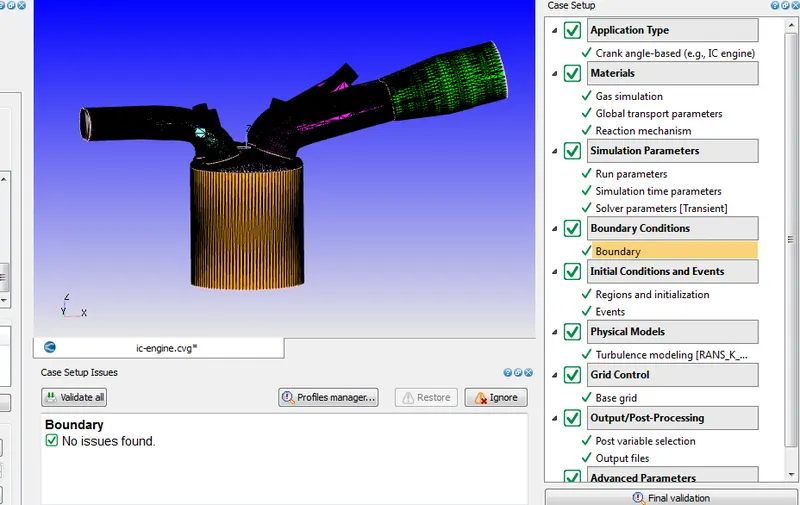
Export all files and run the simulation in Cygwin.
Results:
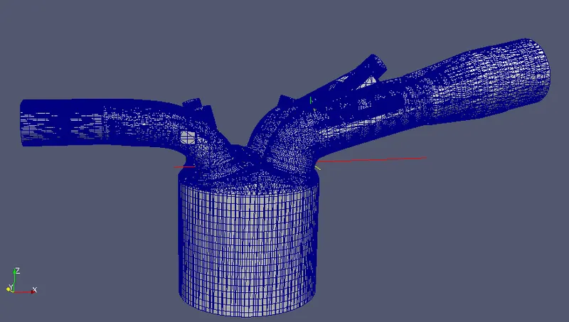
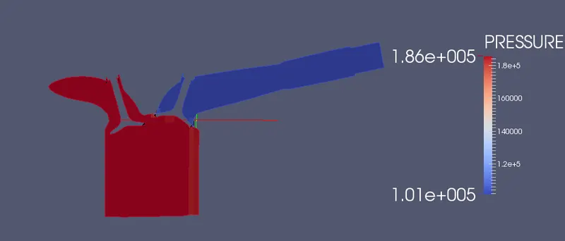
Animation link:
https://www.youtube.com/watch?v=ZI2rFqwZADQ&feature=youtu.be&ab_channel=Harsha