Week 9: Project 1 - Surface preparation and Boundary Flagging (PFI)
AIM:
- To simulate no hydro simulation for an ICE engine.
THEORY:
- An internal combustion engine (ICE) is a type of heat engine in which fuel is burned with an oxidizer (usually air) in a combustion chamber that is part of the working fluid flow circuit. The expansion of the high-temperature and high-pressure gases produced by combustion applies direct force to some components of an internal combustion engine. Typically, the force is applied to pistons, turbine blades, a rotor, or a nozzle. This force propels the component forward, converting chemical energy into useful work.
CASE SETUP:
- The STL file geometry is now loaded into CONVERGE.
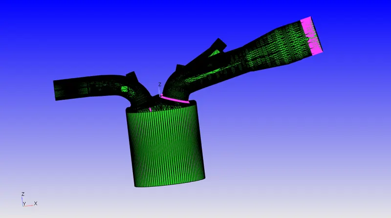
- A diagnosis was run to evaluate the quality of the geometry.
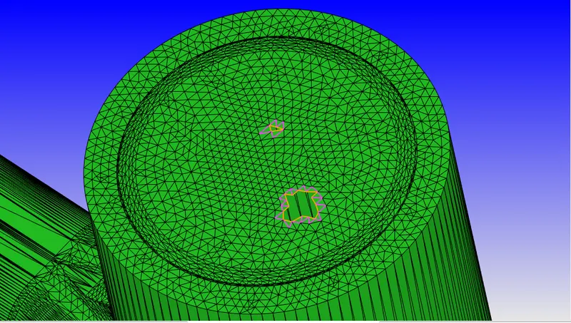
- The errors in the geometry were noticed,
- Intersections, Non-manifold Problems, Open Edges, Overlapping and Normal Orientation
-
Before rectifying the errors in the geometry, boundaries were first identified as follows.
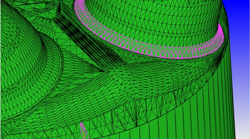
- Geometry Problem Rectification:
1. Open Loop Edges- A geometry that includes open edges in the piston, exhaust port, and liner. The following command was used to correct this.
2. A similar procedure was used to close the other open edges.
3. The intake ports were found to be interfering with the cylinder head in the geometry. In the image below, we can see the intake port colliding with the cylinder head.
4. To solve the previous issue, the intake valve normals were first computed. Normal vectors were identified. The intake valve was then translated by 0.005 to correct the clash. The following command was used to resolve this issue.
5. Geometry- Transform-Directional Vectors (Valve normal values inserted)- Translational amount.
6. Rectification of Normals- All of the normal vectors in the imported geometry are pointed outwards. This was fixed by applying the Geometry-Transform-Normal-Propagate change from a single triangle. This was done to ensure that the Normals pointed in the flow's direction.
RECTIFIED GEOMETRY:
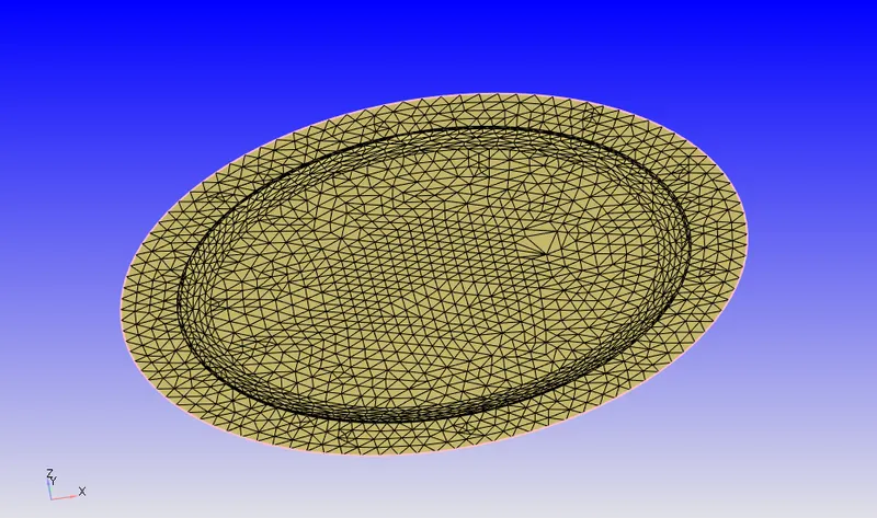
- PISTON:
- LINER:
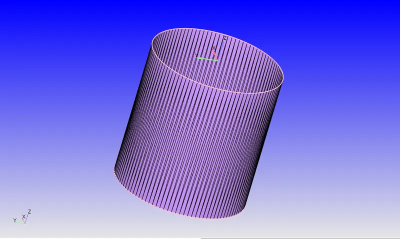
- CYLINDER HEAD:
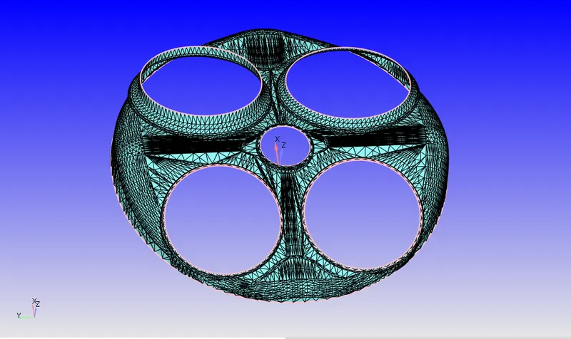
-EXHAUST PORT:
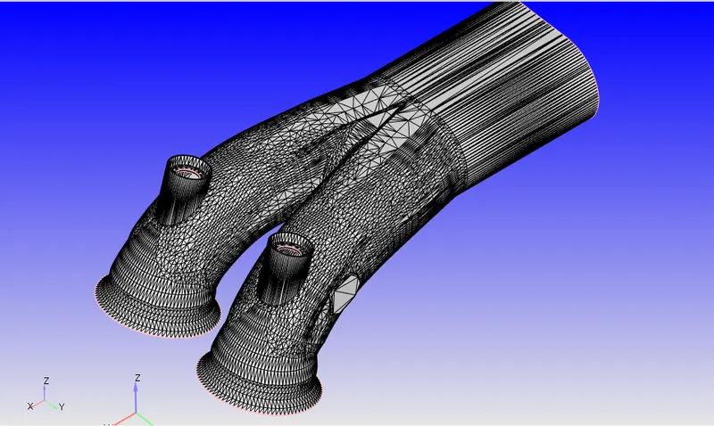
-EXHAUST VALVE TOP:
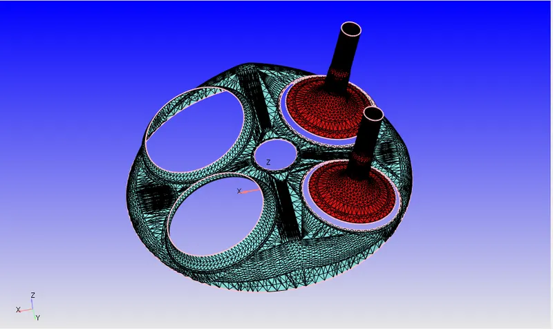
- EXHAUST VALVE ANGLE:
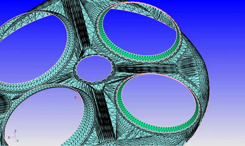
-- EXHAUST VALVE BOTTOM:
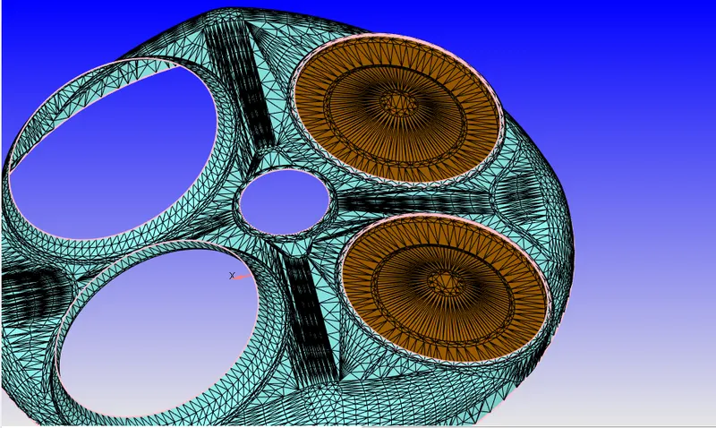
- Similarly for the intake Valve, angle and bottom.
-INTAKE:
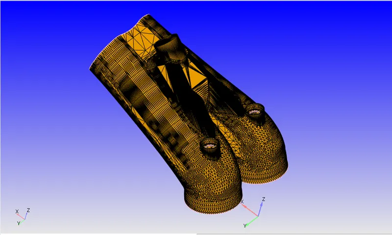
- SPARK PLUG & CRIMINAL:
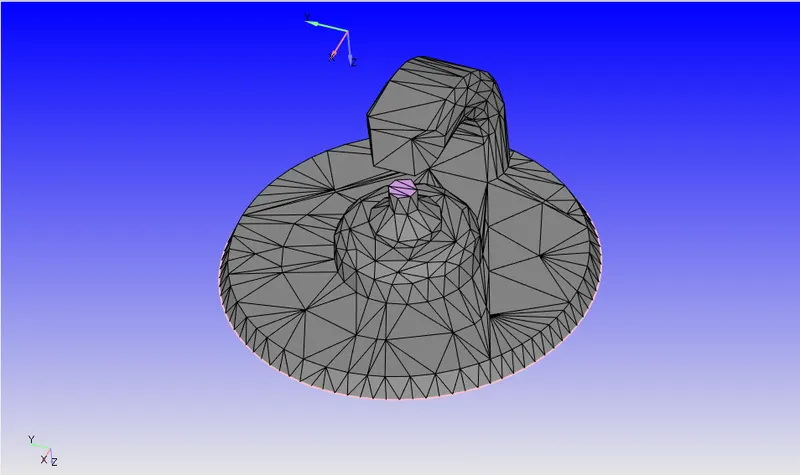
Boundary Flagging:
- Application Type- Crank Angle-based IC engine
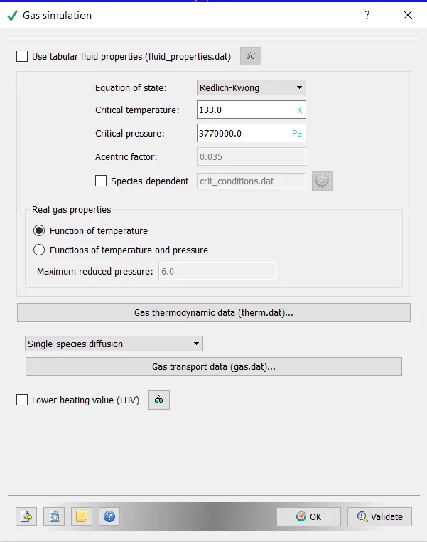
- Materials - Gas Simulation:- Defaults retained,
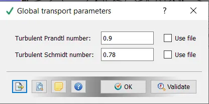
- Global Transport Parameters- Default retained,
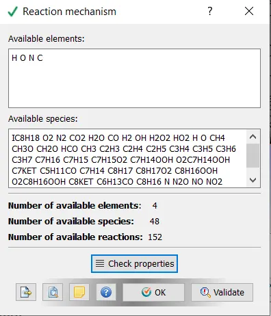
- Reaction Mechanism- For the Reaction Mechanism, The mech.dat and therm.dat files are loaded into the simulation,
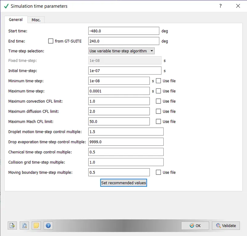
- Simulation Time Parameters:- Whereas the period of an ICE engine cycle is 720 degrees, the start and end time is noted.
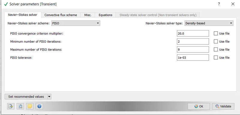
- Solver Parameters (Default):
- Regions and Initialization:
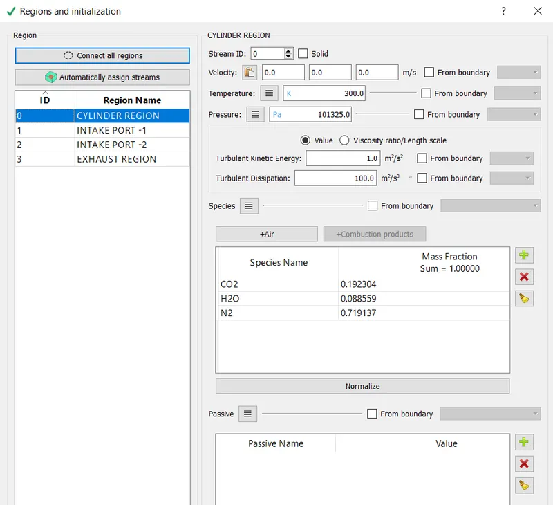
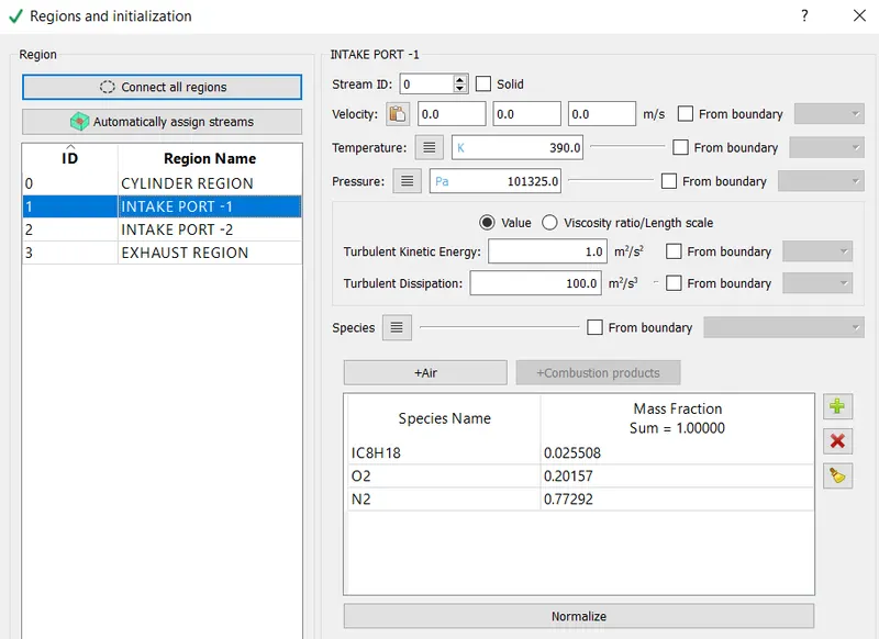
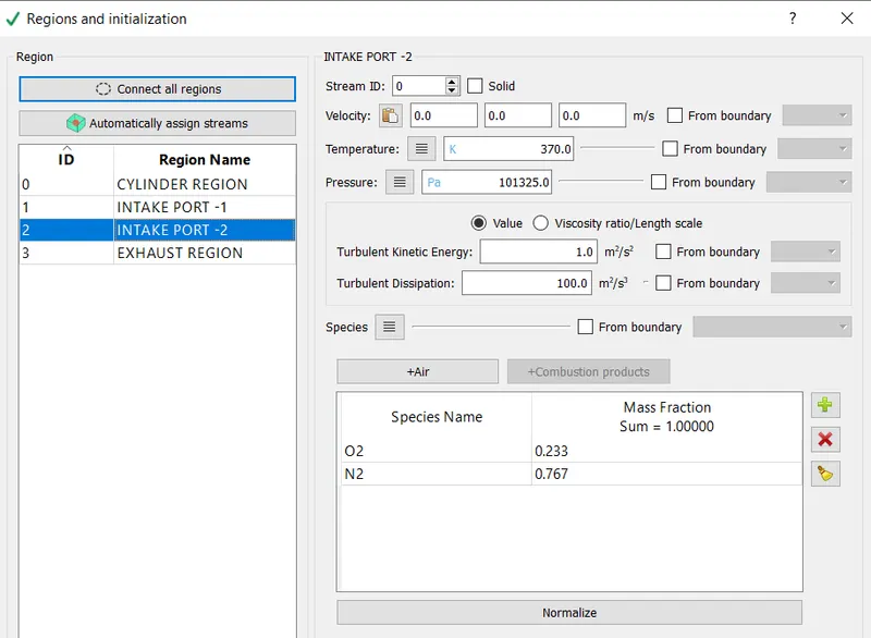
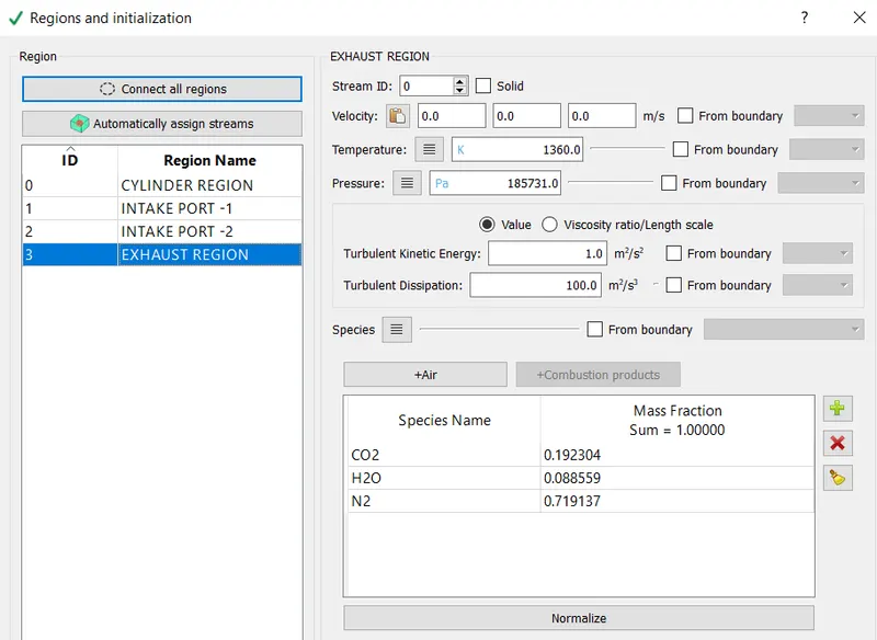
- The ICE engines were classified into four regions, namely Cylinder, intake-1, intake -2 and exhaust region
- Cylinder Region:- The species' mass fractions were calculated using the requirement for complete/stoichiometric combustion.
- INTAKE-1: The mass fraction for the fuel-air mixture was entered based on the typical composition of an ICE engine.
- INTAKE-2: Because air is taken in through intake port 2, the typical air composition has been inserted.
- EXHAUST REGION: Since whatever gas is to be exhausted through the exhaust region comes from the combustion chamber, the exhaust gases have the same composition as the cylinder region.
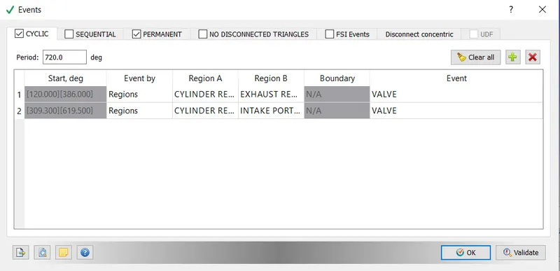
EVENTS:
- Events were created to synchronise the cyclic opening of the intake and exhaust ports. The timing of the opening was determined by inspecting the exhaust. in and intake.in files.
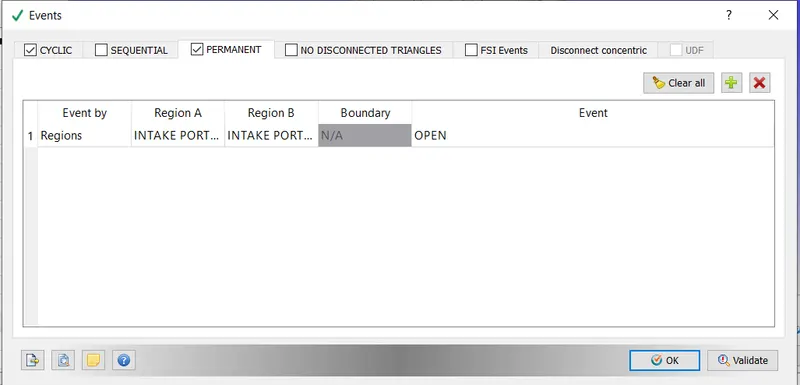
- During the combustion cycle, the intake valves would also be open. As a result, a Permanent event was created.
Boundary condition:
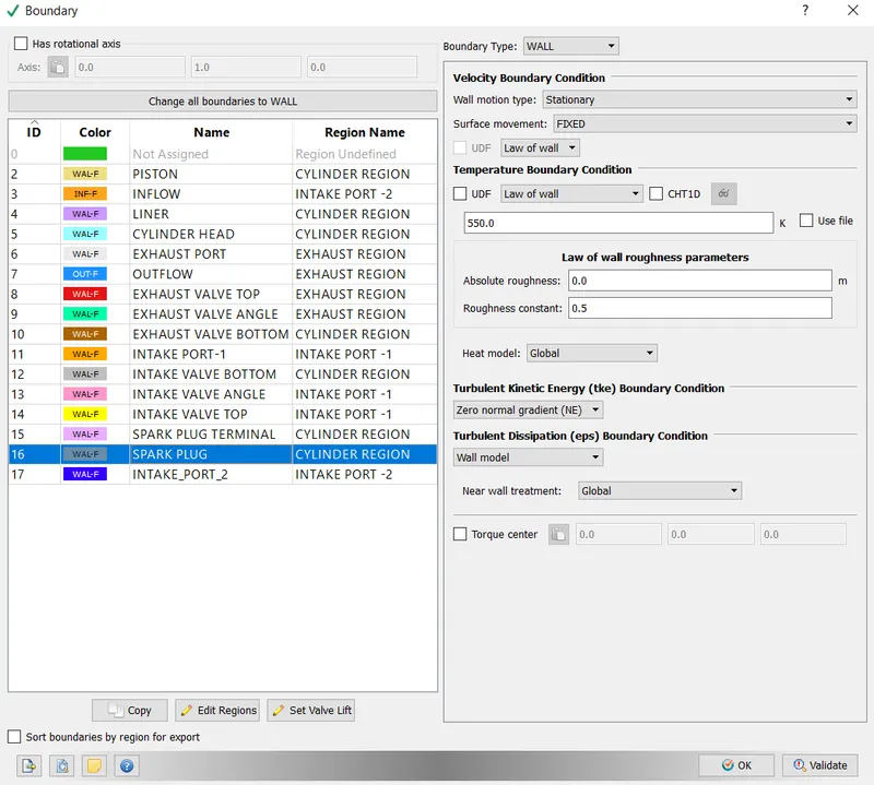
- The ICE engine's components were classified into different regions, as shown below.
-
The boundary condition for each of the components has been set as shown below.
-
Piston:- Boundary Type- Wall,
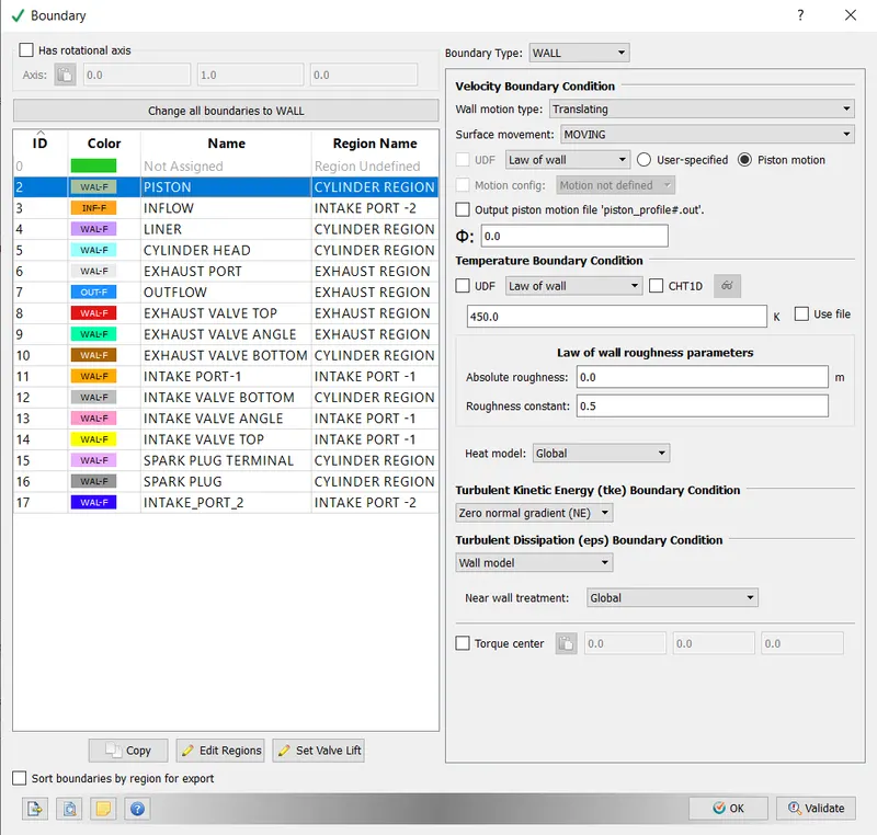
-Inflow:- Boundary Type- Inflow,
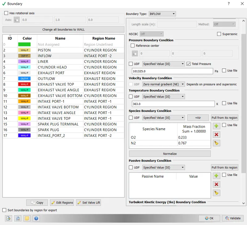
- Liner:- Boundary Type- Wall
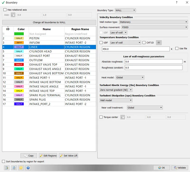
- Cylinder Head:- Boundary Type- Wall,
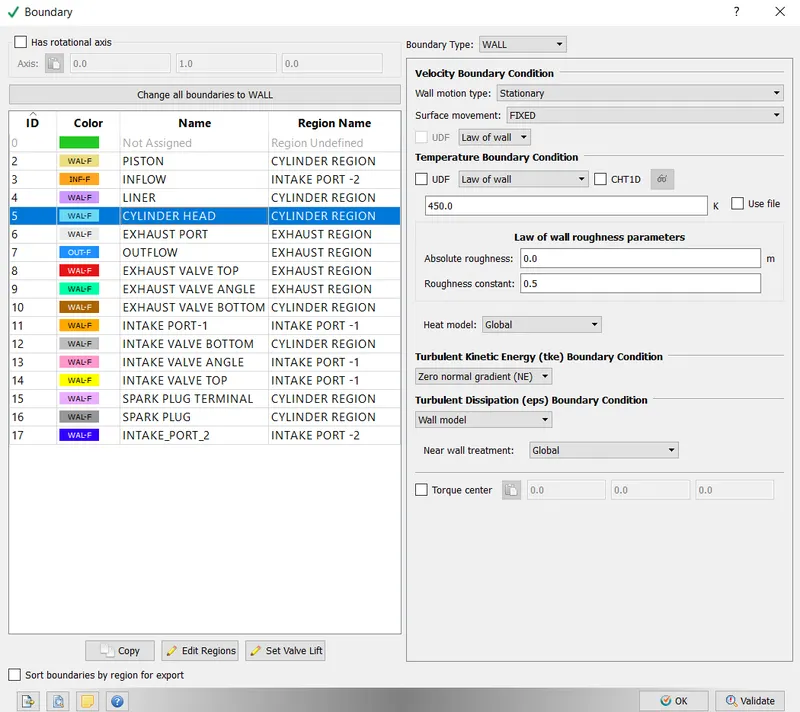
- Exhaust Port:- Boundary Type- Wall,
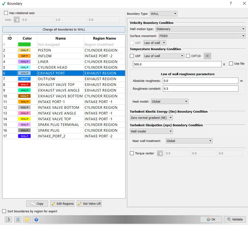
- Outflow:- Boundary Type- Outflow,
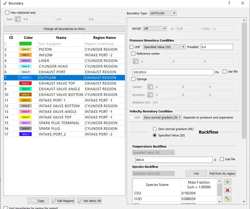
- Exhaust Valve Top - Boundary Type- Wall, Movement as per exhaust_lift.in
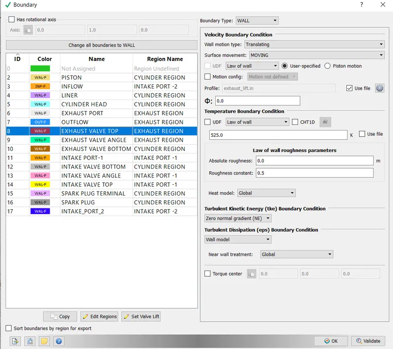
- Exhaust Valve Angle:- Boundary Type- Wall. Movement as per exhaust_lift.in
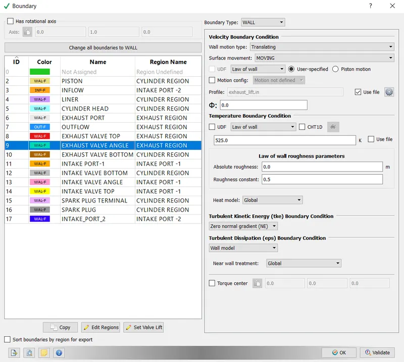
- Exhaust Valve Bottom:- Boundary Type- Wall. Movement as per exhaust_lift.in
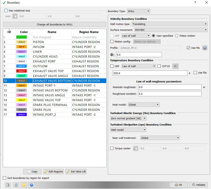
- Intake Port:- Boundary Type- Wall,
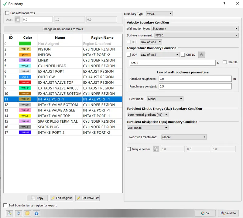
- Intake Bottom:- Boundary Type- Wall. Movement as per intake_lift.in,
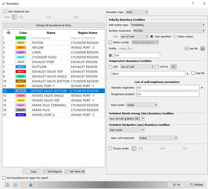
- Intake Valve Top:- Boundary Type- Wall,
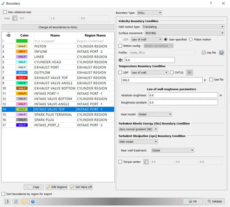
- Spark Plug Terminal:- Boundary Type- Wall,
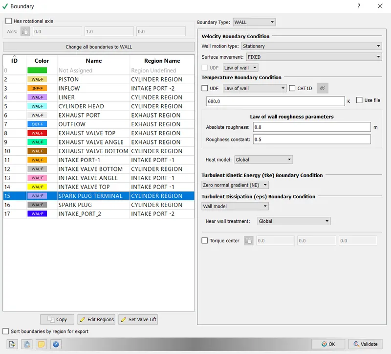
- Spark Plug:- Boundary Type- Wall,
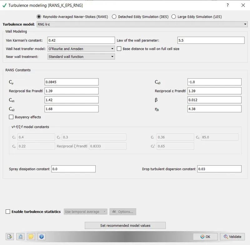
- Turbulent Modelling:- RNG k-epsilon model is used.
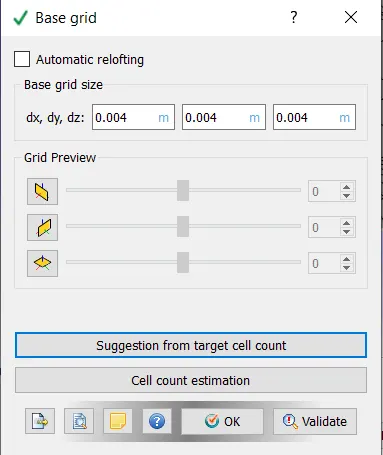
- Base Grid:- An element size of 0.004 m has been selected,
-Fixed Embedding was turned on. This was done to ensure that the mesh was refined locally to better capture the flow properties. Converge employs the octree data structure.
- Intake Valves: Boundary embedding type, Permanent embedding mode The scale factor is 3.
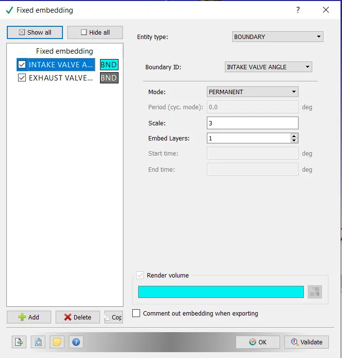
- Exhaust Valve = Embedding type Boundary, mode of embedding- Permanent. The scale factor is 3.
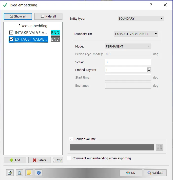
- Cylinder region:-Embedding type Boundary, mode of embedding- Permanent. The scale factor is 3.
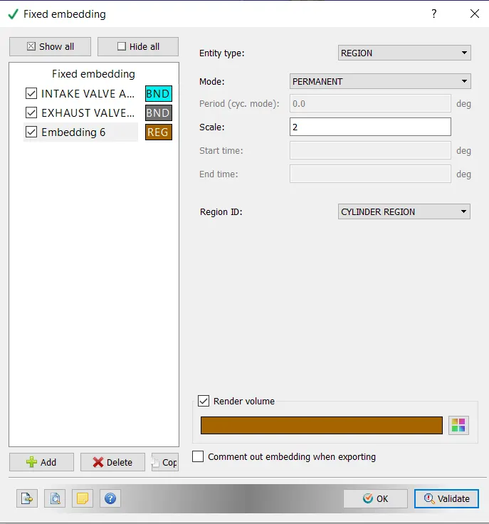
-
Following the above configuration, the input files were exported to a directory. To run the simulation, open Cygwin and navigate to the directory containing the input files, then enter the command "mpiexec.exe -n 4 converge.exe."
-
Following the simulation, the results were converted into a format that was compatible with Paraview. This was accomplished with the post convert.exe command.
RESULTS:
- MESH GENERATION:
- VALVE MOVEMENT:
CONCLUSION:
- The no hydrodynamic model was set up and observed in converge in this project. The valve motion and mesh refinement were discovered to be consistent with the expected result.