Week 9: Project 1 - Surface preparation and Boundary Flagging (PFI)
The Tasks that you need to perform are
1, Boundary Flagging.
2, Surface preparartion.
After setting up the NO HYDRO case set up, make sure you create an animation for NO HYDRO
Solution
Aim
To Surface preparation and Boundary Flagging (PFI)
Introduction
The purpose of task is to do boundary flagging and surface preparation for the given geometry. After that we will run the simulation for no hydrodynamic case setup and see the motion of piston and valves in cylinder for better understanding.
Objective:
The objective of this work is to setup no hydro simulation of IC engine in converge CFD. Other work Includes boundary flagging and model setup for no hydro simulation.
Modelling the problem in Converge Software
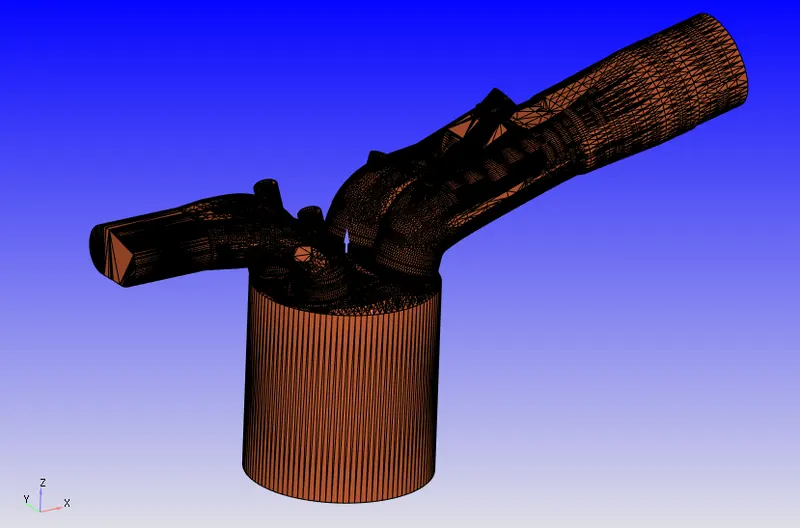
The 3D model is imported in the software.
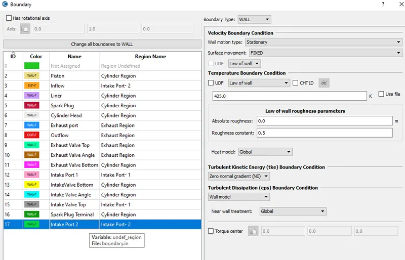
Each of the face is given a boundary name and allotted an ID.
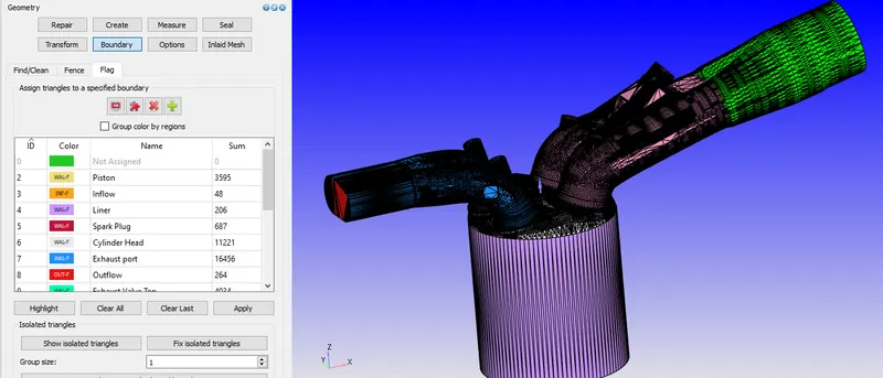
Boundary Flagging is done as:
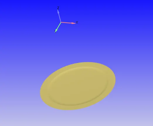
Piston
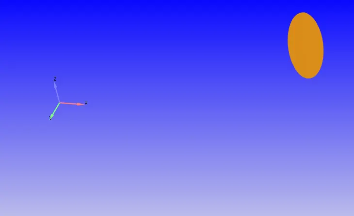
Inflow
Liner
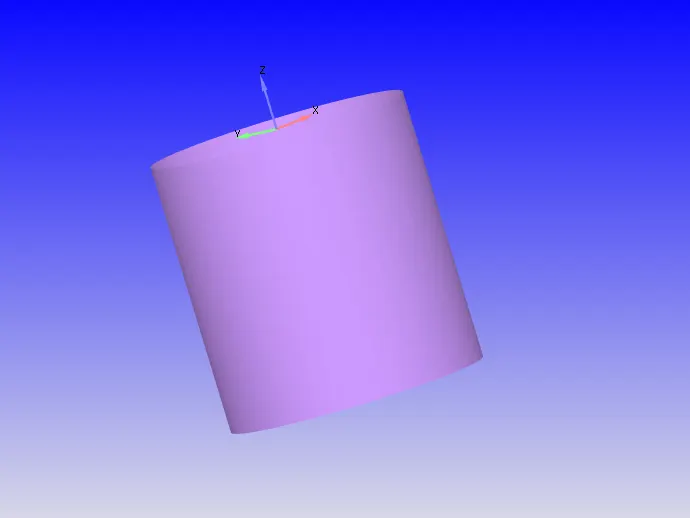
Spark Plug and Spark Plug Terminal
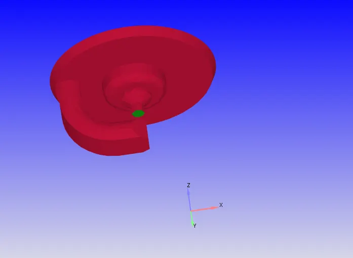
Cylinder head
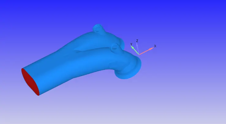
Exhaust Port and Outflow
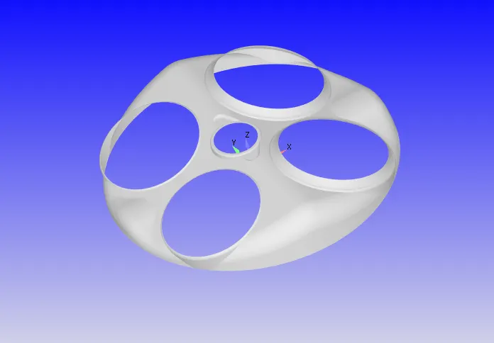
Intake and Exhaust Valves
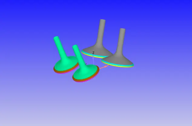
Intake Port 1 and 2
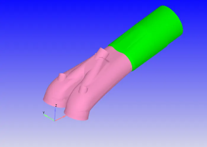
Regions & Initialization:
For initialization, Four different zones are set,
Region1:
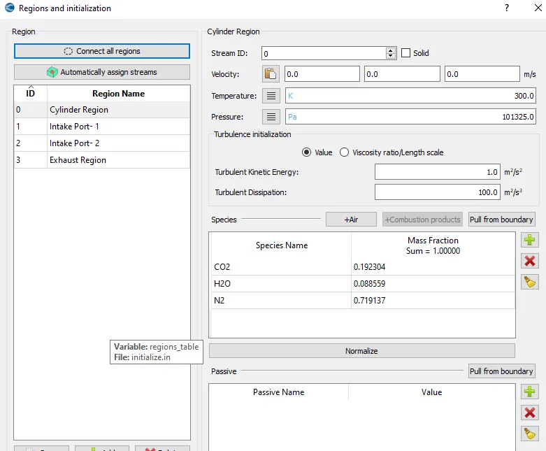
Region2:
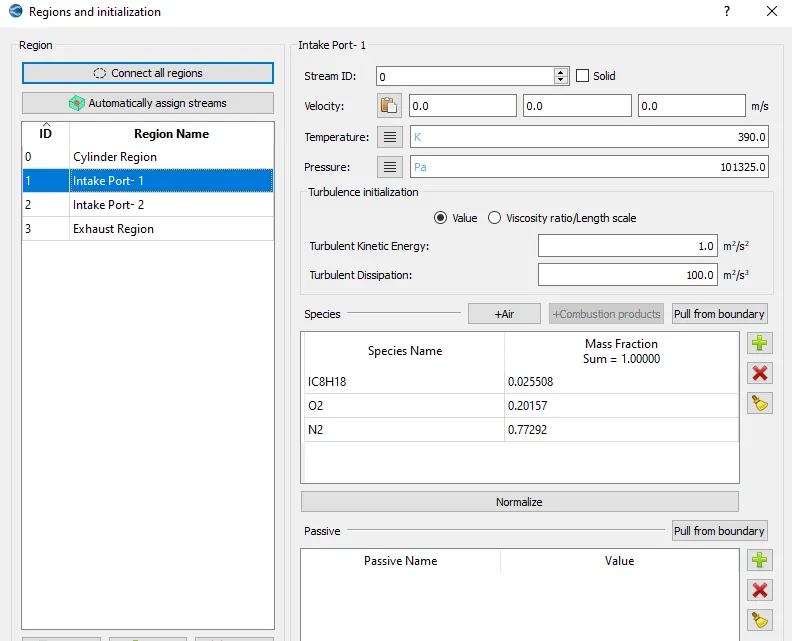
Region3:
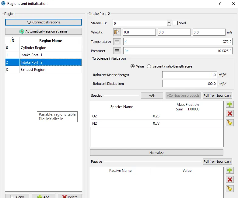
Region4:
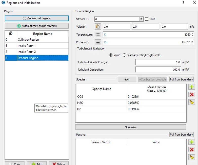
All of the above regions can be seen differentiating in the below attatched image.
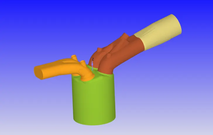
As seen in the image below there is a small gap in the ports and their corresponding valves. So this needs to be opened and closed during the engine working time.

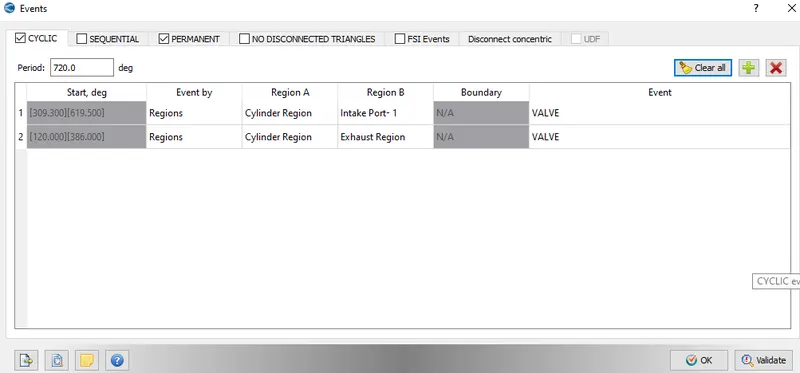
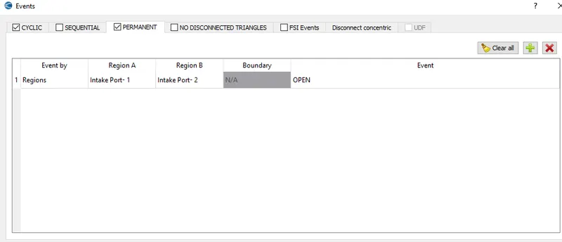
Events
Bothe the Events for the disconected triangles are depicted below:
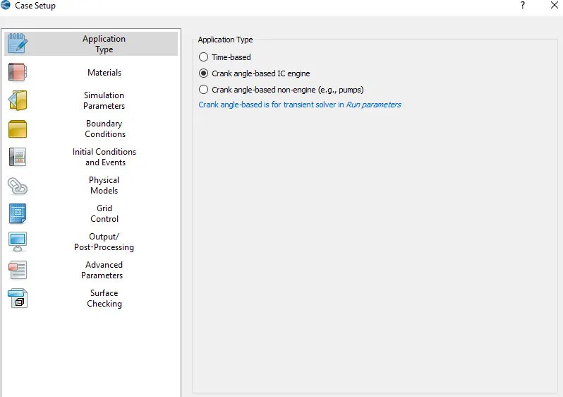
Case Setup:
Since this is a IC engine problem, the procedure to setup it is shown in the steps below.
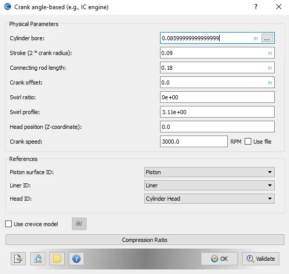
Physical Parameters
The IC engine paramters are shown below:
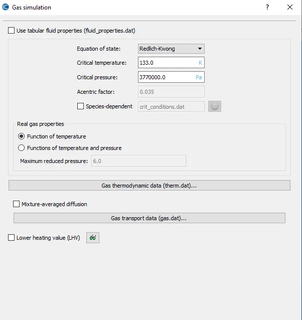
In the Gas simulation tab, default settings are set
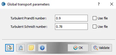
In the Global transport Parameters, defaults are kept to be same.
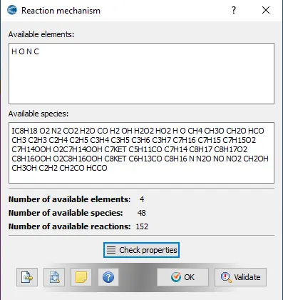
Reaction mechanism
In Reaction mechanism, below added species are used.
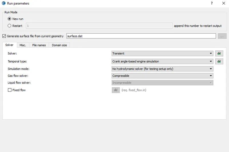
Run Parameters
In the Run parameters tab, transient solver is selected along with simulation mode to be in No hydrodynamic and solver used to be compressible.
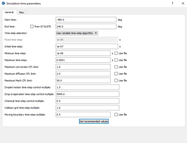
Simulation time Parameters
Since it is a crank angle based problem, the angles are defined in simulation time parameters.
Solver Parameters
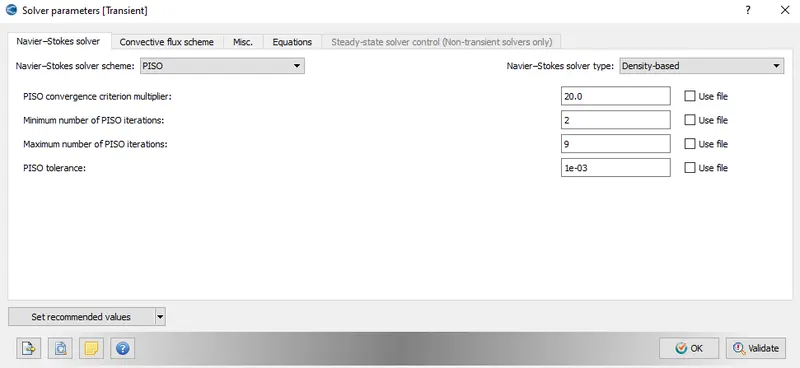
PISO scheme is selected for solving the navier stokes equation and other values are set to be at the default.
Boundary Condition
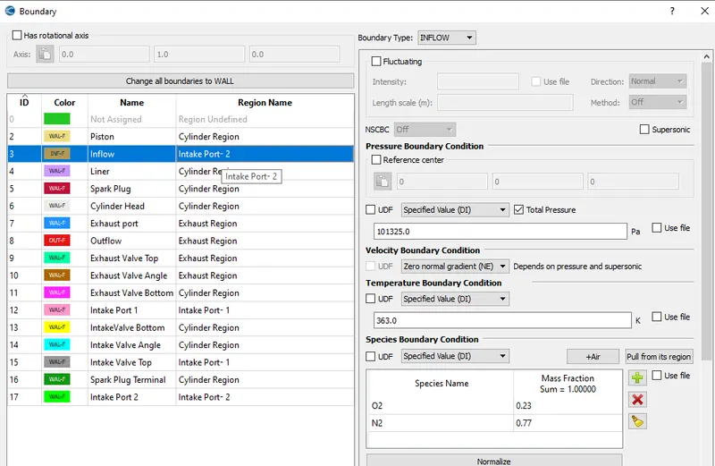
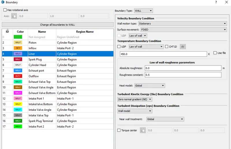
Futher the type of boundary and zone is set to all.
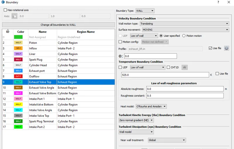
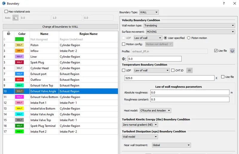
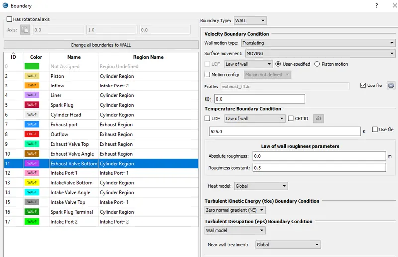
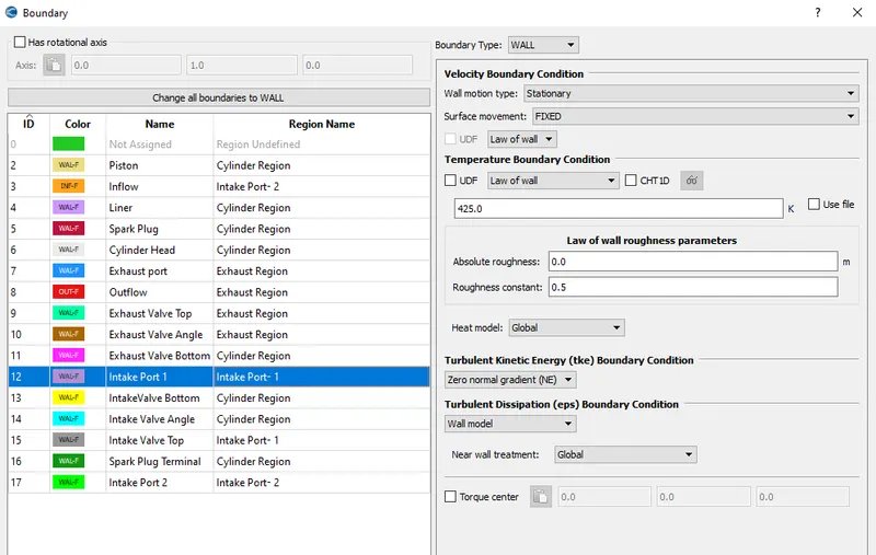
All of the boundary cases are shown below
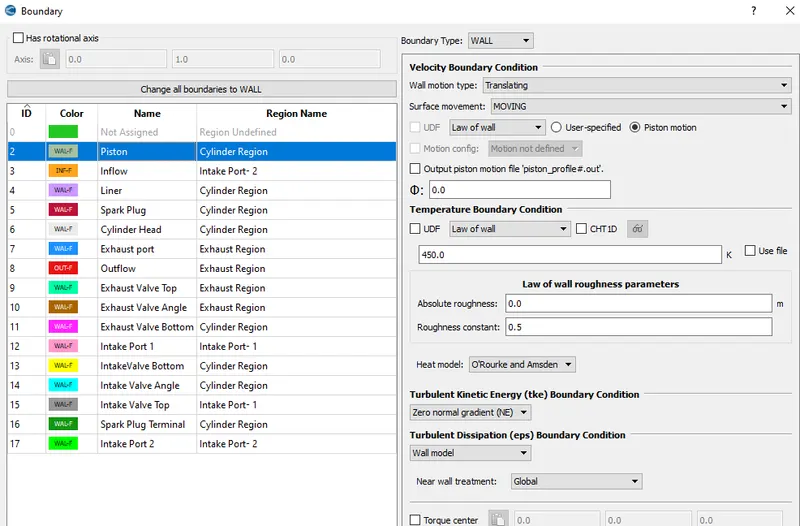
Since piston is translating it has motion so values are applied accordingly.
Piston
Inflow
Liner
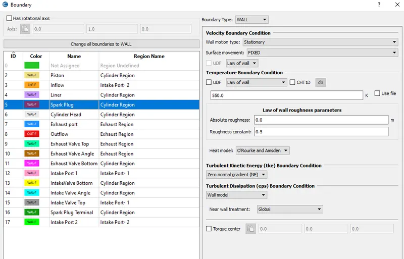
Spark Plug
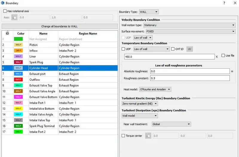
Cylinder Head
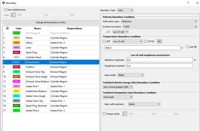
Exhaust Port
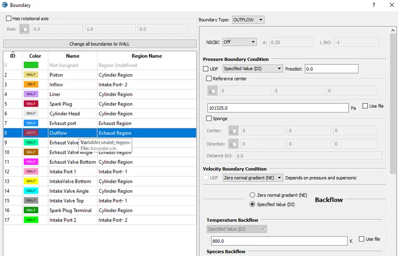
Outflow
Exhaust Valve Top
Exhaust Valve Angle
Exhaust Valve Bottom
Intake Port 1
Intake Valve Bottom
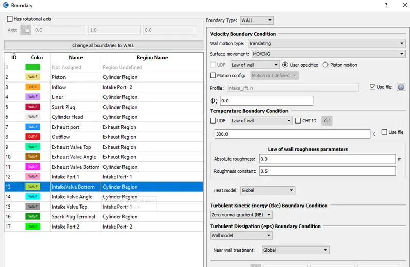
Intake Valve Angle
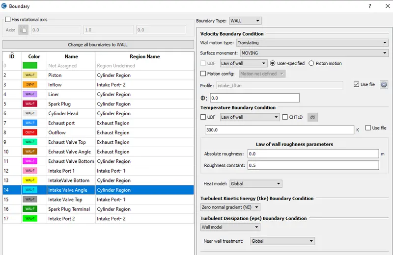
Intake Valve Top
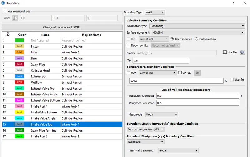
Spark Plug Terminal
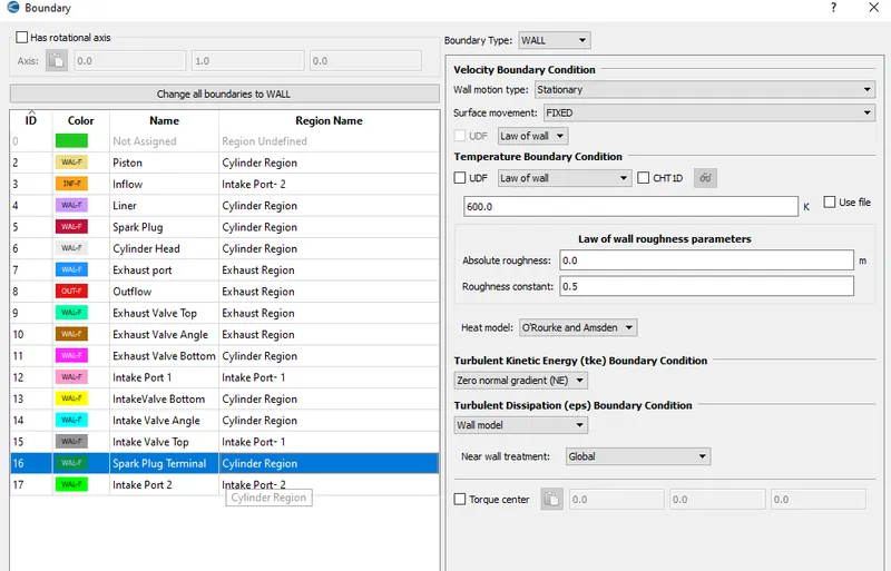
Intake Port 2
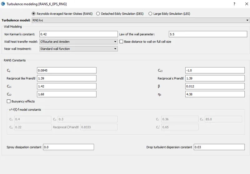
Turbulence Model
For the turbulence modelling RNG k-ε model is chosen with default values.
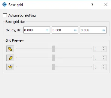
Base Grid
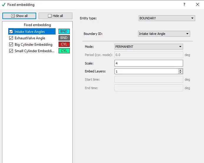
Grid of size 0.008 m is applied in all directions. Fixed embedding is also applied along with this.
Fixed Embedding
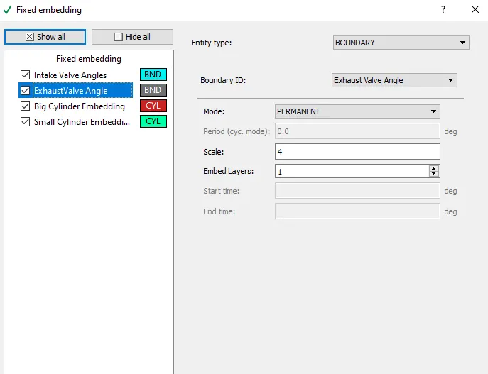
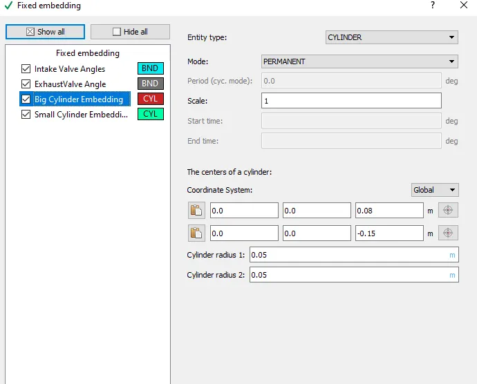
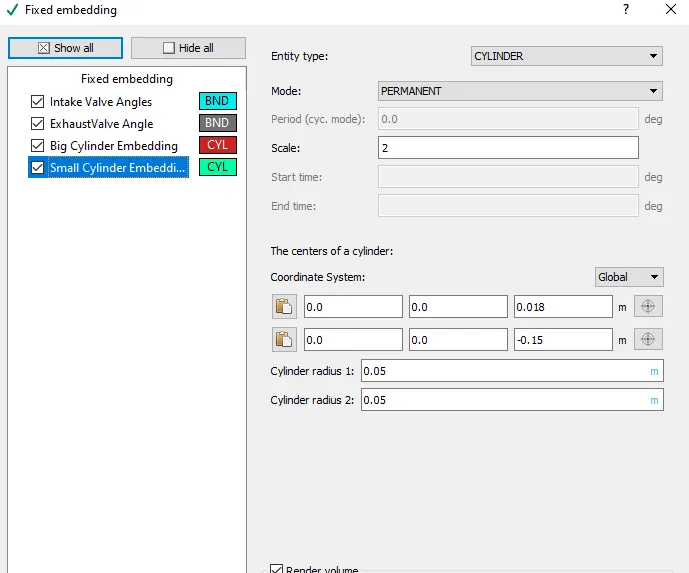
Four fixed embedding parameters are applied as shown below
Intake Valve Angle
Exhaust Valve Angle
Big Cylinder Embedding
Small Cylinder Embedding
Results And Contours
Mesh Contour
At time Step = 100
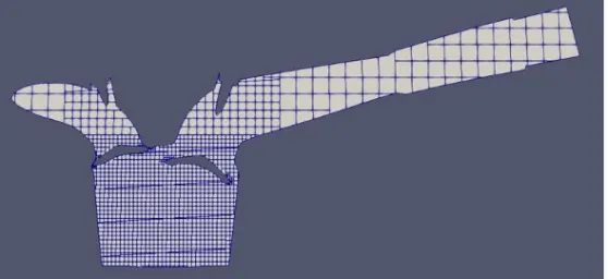
At time Step = 150
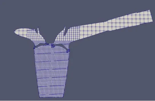
At time Step = 300
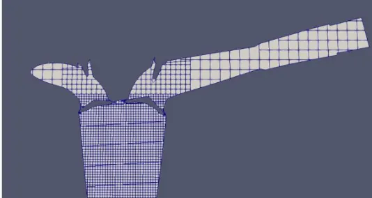
Animation link : https://youtu.be/EmkgJ278Ha8
Full Animation:
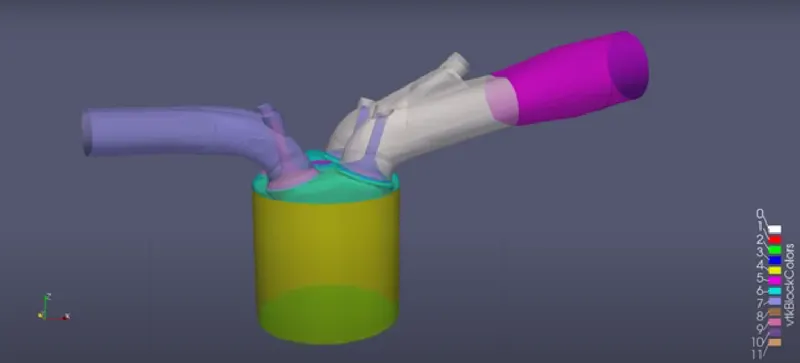
Animation link : https://youtu.be/VVowV7rLrjQ
Conclusions:
- The simulation was set up to check the valve movement and mesh generation in IC Engine Geometry.
- After all the geomtery correction output files are run in paraview. For given geomtery the simualtion is shown in above link.
- In this process is non hydrodynamic. Piston movement is clealy visible from animation
- Surface Preparation and Boundary Flagging is successfully Done