Week 9: Project 1 - Surface preparation and Boundary Flagging (PFI)
Aim - Surface preparation and Boundary Flagging (PFI)
Introduction-
The purpose of task is to do boundary flagging and surface preparation for the given geometry. After that we will run the simulation for no hydrodynamic case setup and see the motion of piston and valves in cylinder for better understanding.
Surface preparation and boundary flagging is important steps before we go case setup. These terms are related to converge software only, in CFD domain we can call surface preparation as geometry clean-up. In simple language, surface preparation is process to detect the error in CAD model and solve the them, if one goes negligence, he will definitely end simulation with wrong results. Boundary flagging is a procedure in which we assign the suitable names to the boundaries, because CFD software does not have intelligence to do the same.
Port fuel injection refers to the system where the fuel is injected in inlet manifold of the engine. The fuel mixes with the air thoroughly because there is lot of time to mix fuel with air, during intake and compression stroke, fuel is mixed with air.
Surface preparation and boundary flagging are major step to begin any simulation, one has to be very careful about these steps, otherwise it will ruin the simulation. In this section we will see the major types of error and their diagnosis, specific to converge software only. Converge automatically highlights the errors by magenta colour, after error check, but have to look at the reason behind the errors then only we can remove them.
Intersections – As the name suggest that intersection of the plane of one triangle to another plane of triangles. Areas and angles less than specified values will be also considered as intersection error. Intersection error can be removed by translating or rotating the surfaces or increasing the angle or areas, if any.
Nonmanifold Problems – Nonmanifold Problems arises when an edge that is shared by more than two triangles or A vertex that connects two otherwise disconnected pieces of geometry. This is error will be removed automatically after assigning the boundaries or regions.
Open Edges – this problem arises when there is an open edge, since converge works on the volume so it’s does not allow open edges. Make patch or stitch triangles to remove this error.
Overlapping triangles - Triangles that meet other triangles at an angle less than the specified value, in degrees. Delete the overlapping triangle and make patch if necessary.
Normal orientation – this problem arises a triangle have different orientation of normal than its adjacent one. This error can be removed easily by translating the normal.
Steps –
- Geometry
- Define the boundary
- Case setup
- Simulation
- Post processing
- Outputs
- Conclusion
Geometry :
Split the geometry into a meaning full boundaries
1. Import the file in the CONVERGE.
2. From the diagnosis it can been seen that our geometry showing problem in the traingle
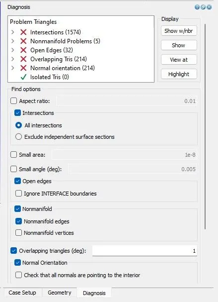
first i need to fix this, so this i am going to flagging the boundary so as we flag we have multiple boundaries we will hide some parts quite easily and then we will do the clean up and we have to readjust the way we flag the boundary if required.
So firstly i am going to do boundary flag and create multiple boundaries because we need a lot.
so first thing is isolate selection which can be done easily so i am going to use Angle method and select the piston
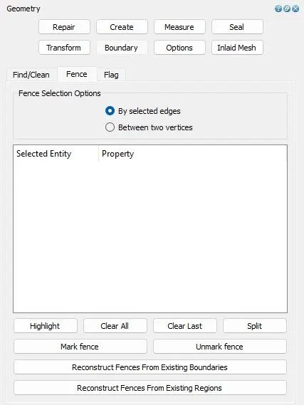
Let's create Fence at the boundary of the piston.
Geometry --- > Boundary --> Fence
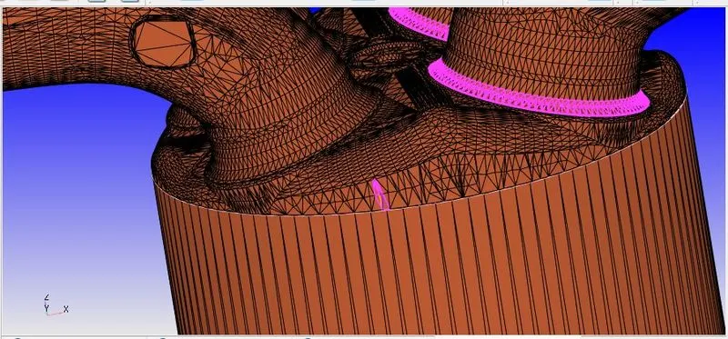
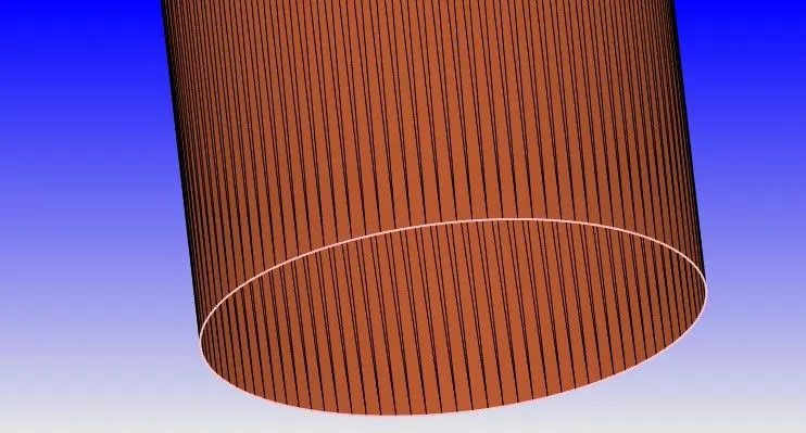
Now go to boundary --> Flag and i m able to select the piston and click on apply and i am going to call this 'liner'
Make boundary fence on the cylinder head
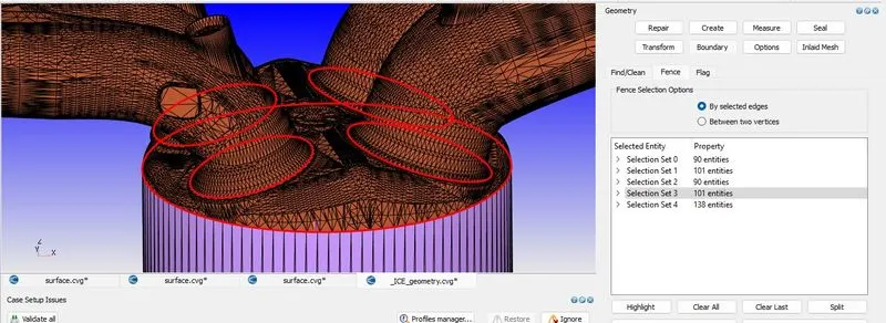
Now go to flag --> choose method boundary Fence and select the boundary no. 5 and click on apply and give it name as 'Cylinder head'.
so now as i can see that the inlet valves are intersecting with the cylinder head port that is because of CAD model made by the engineer actually they pushed opned the valve so much so it can actually interfering with this cylinder head. So fix that we just have to pushed opned the valve so that the intersection do not occur and then push it back again to the right location.
By slection the Angle Method create a boundary of Exhaust port.
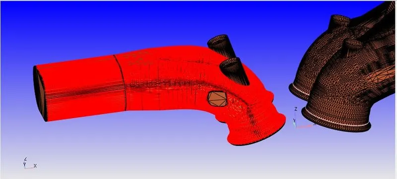
and same as for the Outflow boundary.
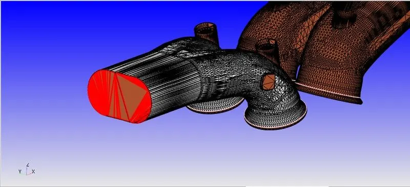
Now divide the valve into 3 different parts so i am going back to Fence and select the 3 different Fences as shown in the figure given below .
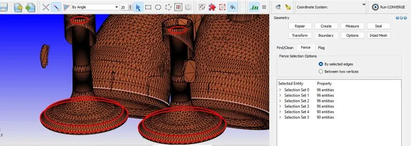
Now select the 'By boundary Fence' and give it name as 'Exhaust Valve'.
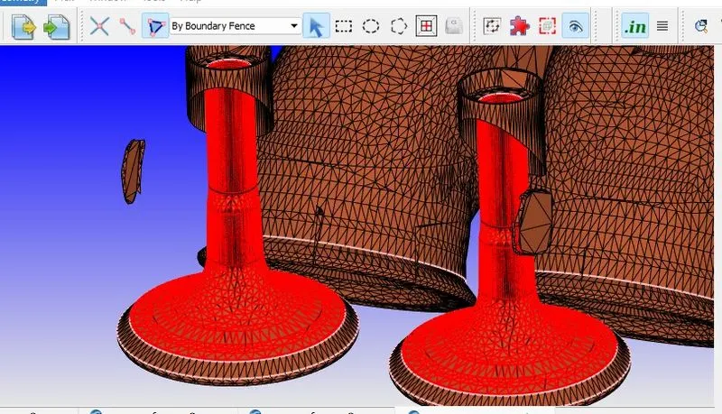
Simultaneously the exhaust valve Top boundaries and the Angle Boundaries' as shown in the given below.
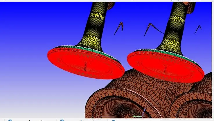
after hiding the all exhaust values we can see that so of the material this belong to exhaust port so what i can do group select and the exhaust port and click apply.
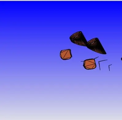
so for the traingle in the inlet port which we called as ring triangle so that need to be part of the intake port here create a boundary Fence and used 'Boundary Fence method' and added to the exhaust port.
and do the same thing to the other side as well.
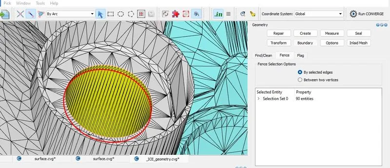
On the other hand,
So let's come to the Inlet port and create 5 more boundaries here.
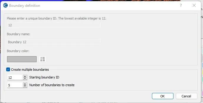
and click on the Reconstruct Fences from Existing boundaries and go back to Flag and choose 'By boundary Fence' method and
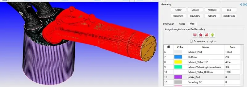
select intake port and add that to bounday no. 12 and we can call it intake port.
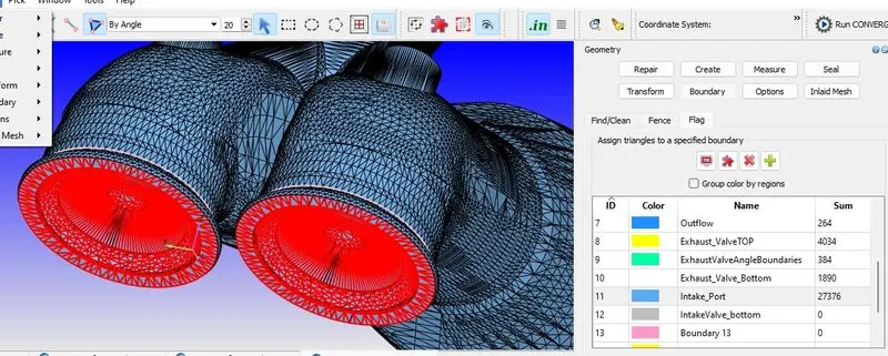
and come up with intake port individually and choose the Angle method and capture the bottom phase.
And now create the boundary Fences by using 'Arc' method
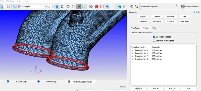
Now again click on Reconstruct Fences from Existing boundaries
go back to boundary flagging and select the below slection and give name it as 'IntakeValveBottom'
And also add IntakeValveAngle as i mention given below :
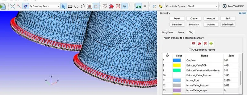
Le's Go to Flag and create two Arc to Capture Ring Traingle
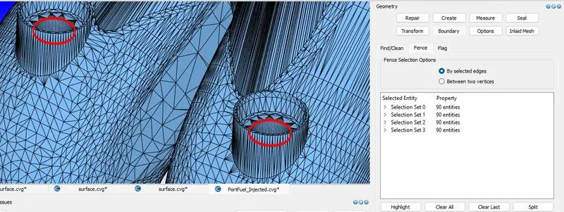
and Go to Flag and use 'BoundaryFenceMethod' and added to the boundary no. 15 which is called as IntakeValveTop.
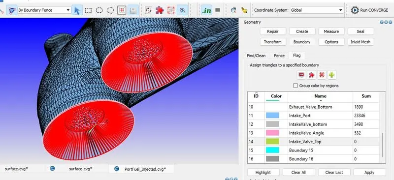
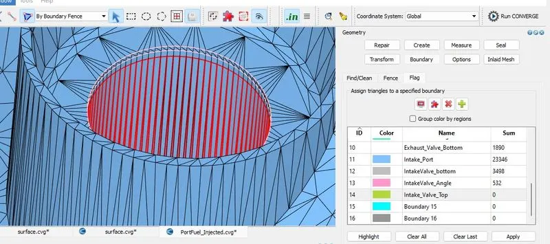
Now we are left with INTAKEPORT and i m now move my Valve so that these intersection erros not occur. so how i can Move it ? so i simply use Translate Tool
so Go to Translate so for this i need to measure the valve normal si for this
Go to --> Measure --> Direction --Arc normal and select the 3 points and make sure that 3 points on the same circle and hit enter on apply.
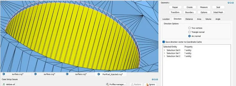
and i immediately get the Arc normal and select this and copy
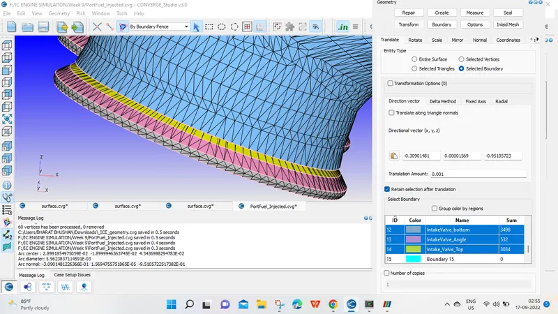
Go to Transform - > Translate --> Selected Triangle and copy the Arc Normal here and select the Intake ValveTop, Angle and Bottom and translate it as 0.001mm
and it no longer intersected.
Now i am going to patch the open edges.
And also eliminate the orientation error by clicking NORMAL
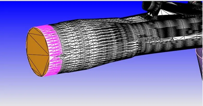
So after Assigning the bundaries
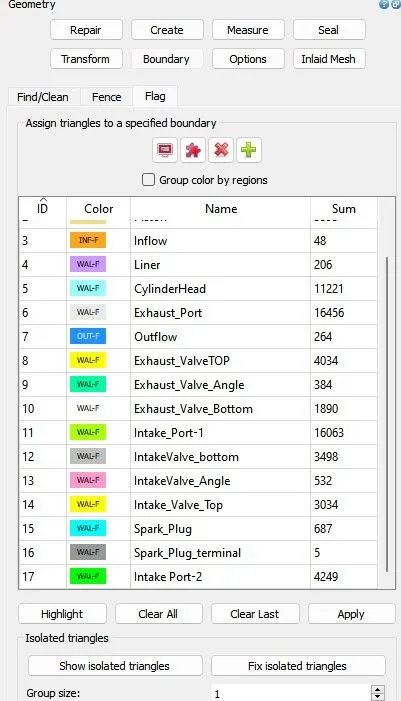
After completing the no Diagnosis error my geometry looks like
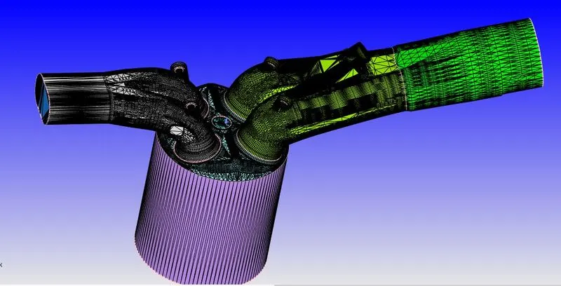
By hiding edge figure going to be looks like
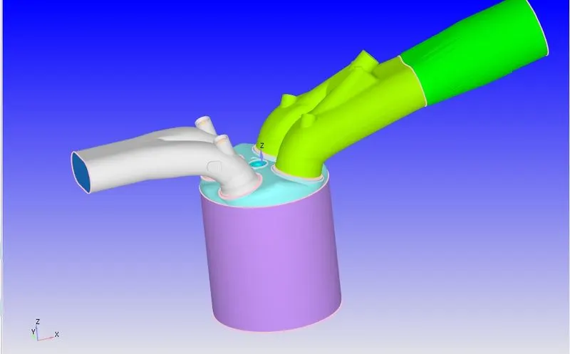
After boundary flagging and surface preparation our geometry is looks as shown below :
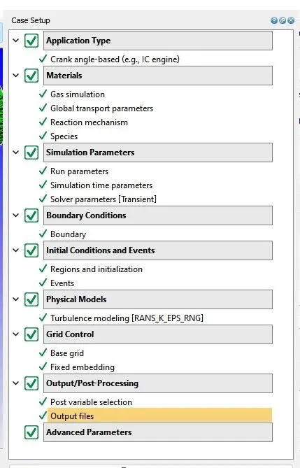
Case Setup :
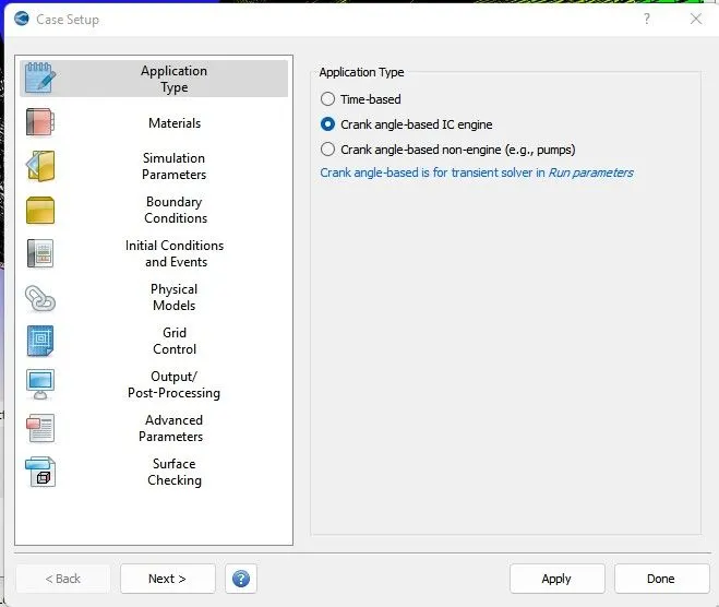
Application type –
Choose Crank angle based application type. Enter the cylinder bore stroke and other details from engine specification sheet.
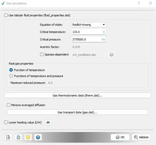
Gas simulation –
Select the Redlich kwong equation for gas simulation. the critical temperature and pressure are already pre-defined. Import the therm.dat file in gas thermodynamic data.
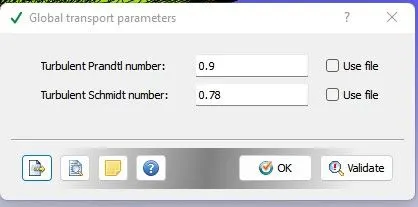
Global transport parameter –
Turbulent Prandtl no and Schmidt no is mentioned below.
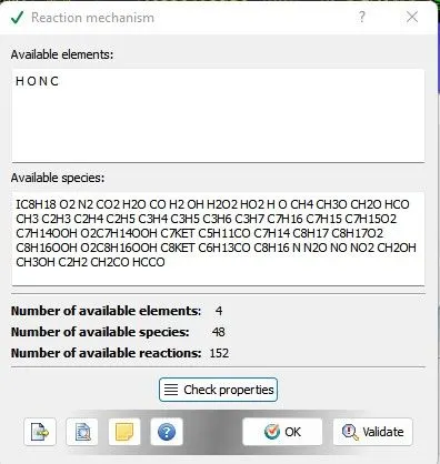
Reaction mechanism –
For reachion mechanism import mech. Dat file for reaction data of all species.
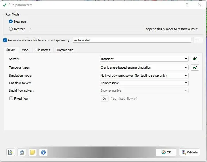
Simulation Parameter –
Run parameter –
We will run the simulation for transient solver. Simulation mode will be no hydrodynamic.
Simulation time parameters-
start time and end time for simulation will be as follow .
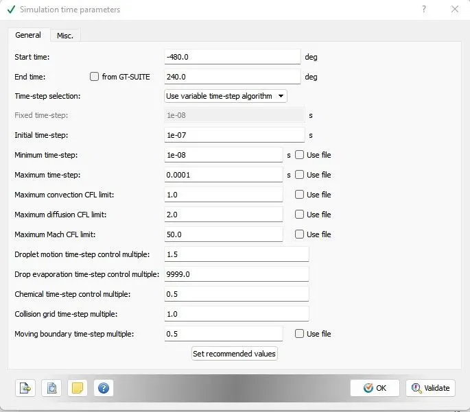
Solver parameters- Default
Boundary condition –
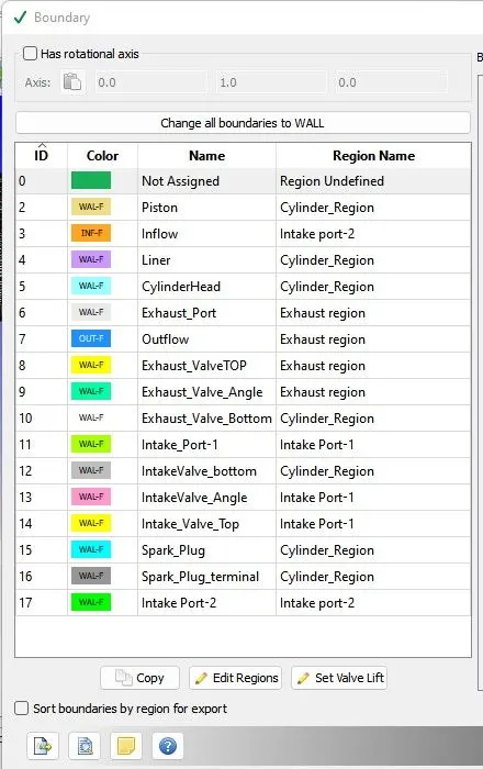
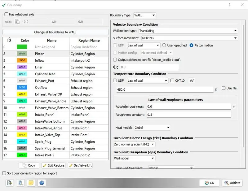
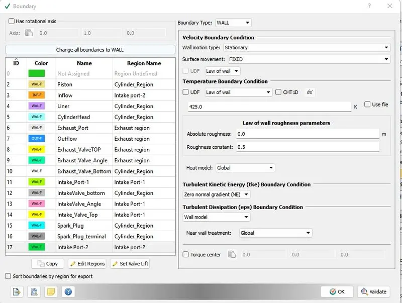
Boundary condition for different boundary is as follow –
2. Piston
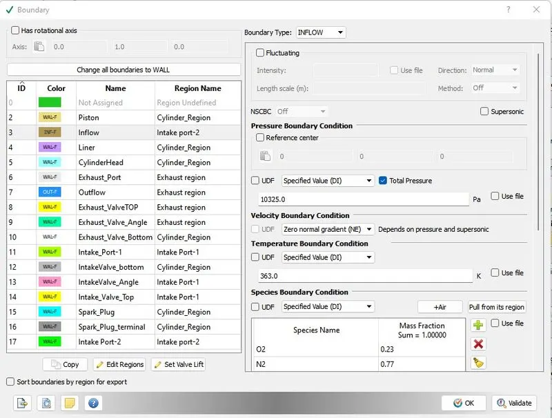
3. Inflow
4. Liner
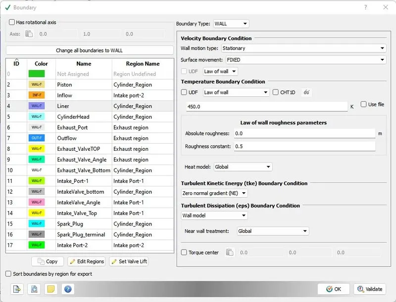
5. Cylinder_Head
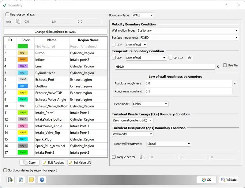
6. Exhaust_Port
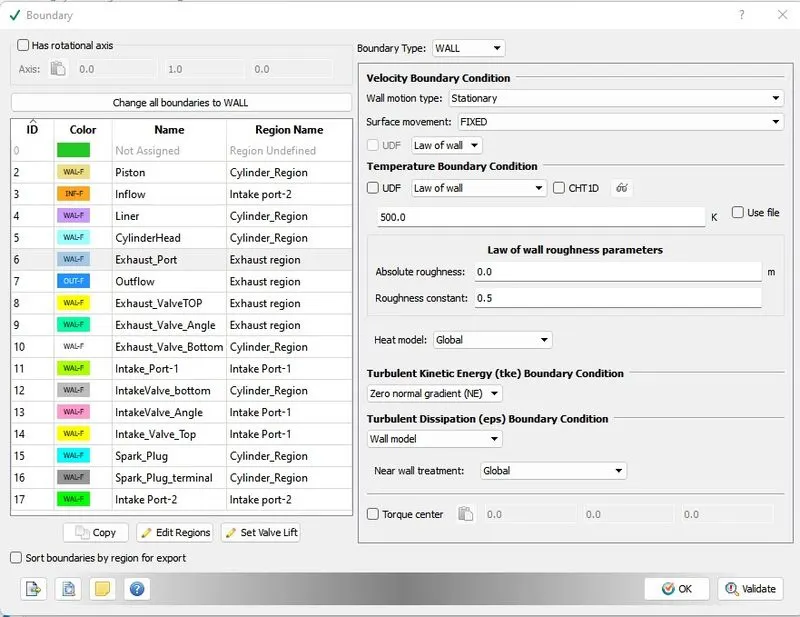
7. Outflow
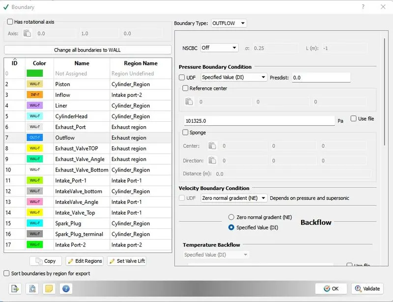
8. Exhaust-Valve-Top
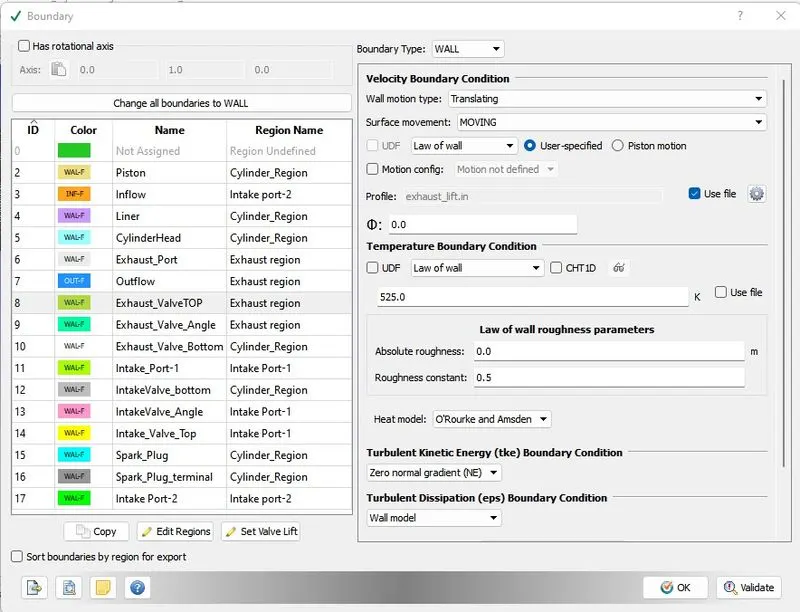
9. Exhaust-Valve-Angle
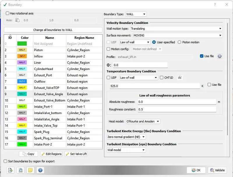
10. Exhaust-Valve-Bottom
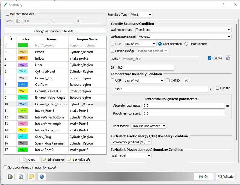
11. intake-Port-1
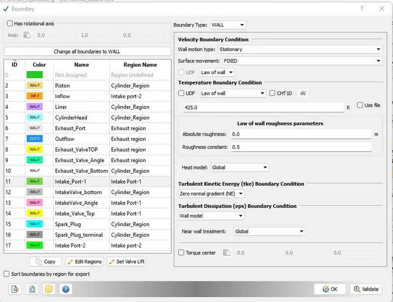
12. intake-Valve-Bottom
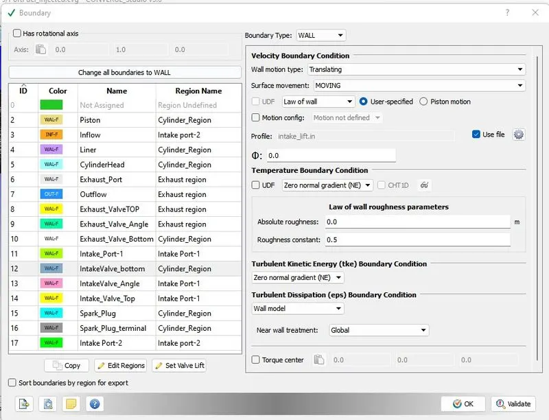
13. intake-Valve-Angle
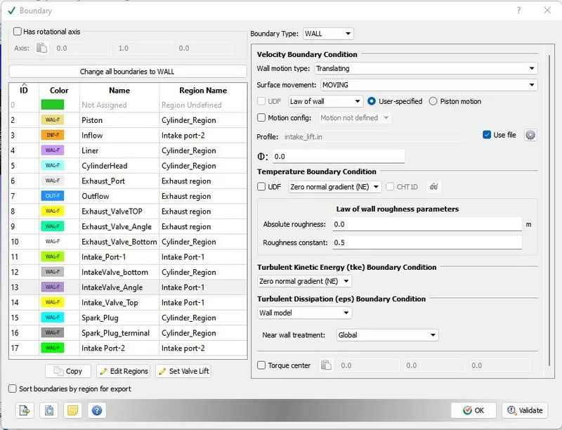
14. intake - Valve -Top
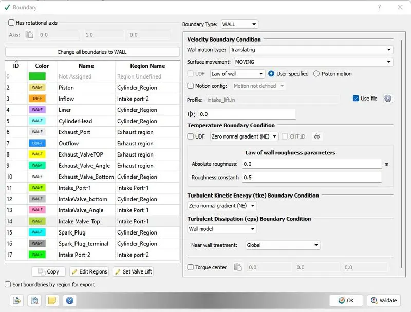
15. Spark Plug
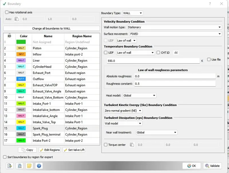
16. Spark Plug Terminal
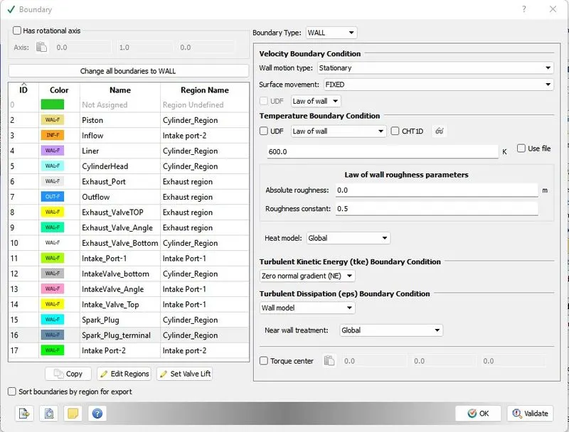
17. intake Port 2
Intial condition and events –
Basically as per geometry 4 region are defined that is
0. Cylinder Region
1. intake port-1
2. intake Port 2
3. Exhaust Region
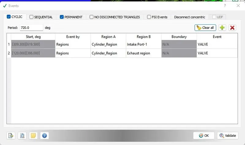
Events –
As per the valve timing of inlet and exhaust valve the cylinder region has to connected and disconnected . events are defined below in cyclic tab for inlet valve , exhaust valve and cylinder region
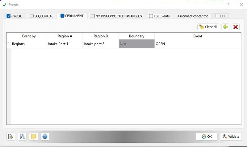
For inlet port 1 and inlet port 2 event is defined in permanent tab .
Physical models –
K-epsilon Model used here
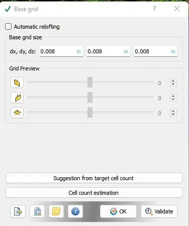
Grid control –
Base grid – dx - 0.008
dy – 0.008
dz – 0.008
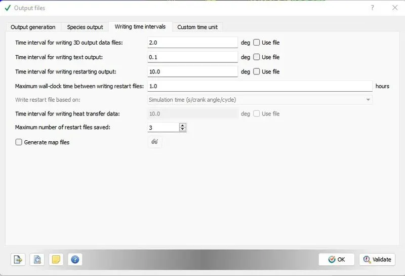
Output processing Advanced parameter - Default
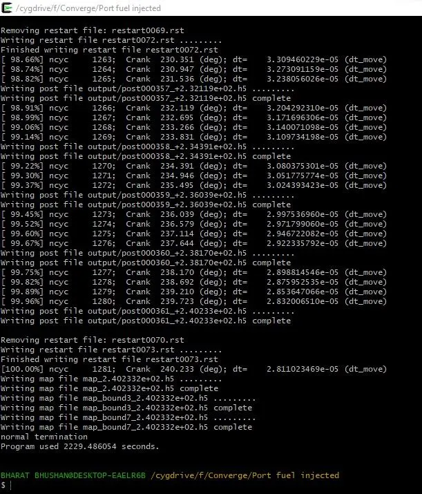
After case set up exports the file to defined folder. Run the simulation in the Cygwin.
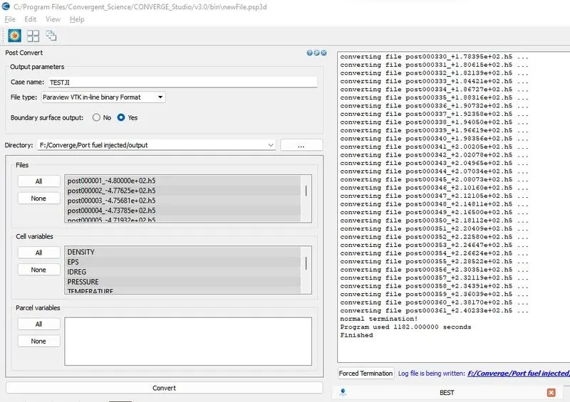
Generate the output files. As output file is generated run the post processing in Converge.
Open the output file in paraview for the mesh view and simulation.
Simulation link:
Google drive link :
https://drive.google.com/file/d/1lwEsTX7fWDrUMQDurmFtoYBP4nfX3UO5/view?usp=sharing