Week 9: Project 1 - Surface preparation and Boundary Flagging (PFI)
Aim:
To setup and simulate a no-hydrodynamic case for the IC engine
Objectives:
- Diagnose and repair the errors for preparing the surface from the imported STL file.
- Perform boundary flagging to setup the case.
- Provide the appropriate boundary conditions and run a no-hydro simulation.
Geometry:
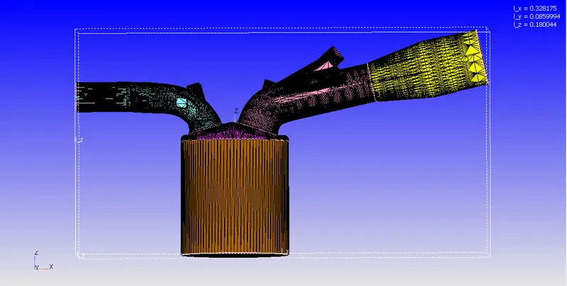
In the current study, we consider a single cylinder of an IC Engine, with intake and exhaust port. The total length of the geometry is ~0.328 m, ~0.086 m and ~0.18m in the x, y and z directions respectively. The intake and the exhaust port also have valves which will control the flow of air and fuel into and away from the main cylinder. The piston of the IC engine is modelled by a single surface with appropriate moving boundary conditions. An illustration of the modelled IC engine along with it dimensions is as follows
Surface preparation:
After importing the STL files, we first run the diagnosis check in the CONVERGE Studio to get an idea of the potential problems in the geometry. An image of the errors and their location on the geometry is as follows
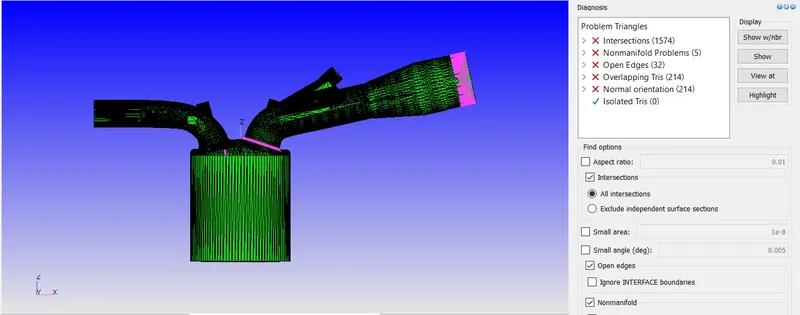
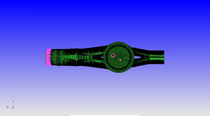
We observe that most of the intersection errors are between the cylinder head and the intake port because of the position of the intake valve. To mitgate this intersection problem, we translate the intake valve by 2mm into the cylinder head. Next, we perform a correction for the overlapping triangles present on the cylinder head and the intake port by using stiching and patching repair tools. The open edges present on the piston is mitigated by closing them using a patch repair tool.
Boundary Flagging:
The boundary flagging in the current study is performed in a specific manner such that the separating different regions becomes very feasible. The name of the flags are provided in such a way that the correspond to the actual parts present in the IC Engine. The figure containing all the different boundary flags is as follows. The color of the flag matches the one present in the first figure of the report.
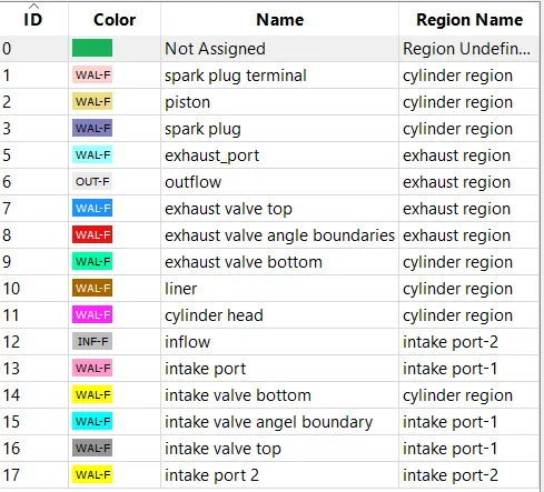
To have more control over the geometry, we split the input port into two halves, so that the air intake and the fuel inflow boundary conditions can be seperated. The intake and the exhaust valves are seperated into three distinct boundaries as they will be separating two regions and to facilitate proper generation of the disconnect triangles generated by the CONVERGE Solver . The exact boundary conditions for each flag and their values are reported in the Case setup section.
Case Setup:
The case setup tree for the current study is set as follows
- Application type:
- Since we are simulating an IC Engine, a crank angle based application is chosen
- Materials:
- We chose a gas type simulation abnd enable the reaction mechanism.
- The default values for the global transport parameters is used
- For the reaction mechanism, we use a custom mech.dat file and the thermodynamic data related to the species mentioned in the mech.dat file is supplied by the therm.dat file.
- Simulation parameters:
- We choose a transient, compressible crank angle-based engine simulation solver. To validate that the setup is accurate we use the no hydrodynamic solver simualtion mode
- The start time is set to -480 degrees (the start of the exhaust stroke) and the simulation is carried out for one entire cycle (720 degrees) so the end time is set to 240 degrees. Initial time step is set to 1e-7 and the minimum and the maximum time step are set to 1e-8 and 1e-4 respectively. The CFL numbers are set such that the CFL criteria is satifised
- The Navier-Stokes solver is chosen to be a PISO Density based solver type with default values.
- Boundary Conditions:
- spark plug terminal: Stationary, fixed wall. Temperature and velocity: Law of the Wall with 600K and TKE: zero normal gradient, eps: Wall model
- piston: Translating, moving wall. Temperature and velocity: Law of the Wall with 450K and TKE: zero normal gradient, eps: Wall model
- spark plug: Stationary, fixed wall. Temperature : Law of the wall with 550K, velocity: Law of the Wall and TKE: zero normal gradient, eps: Wall model
- exhaust port: Stationary, fixed wall. Temperature : Law of the wall with 500K, velocity: Law of the Wall and TKE: zero normal gradient, eps: Wall model
- outflow: Pressure: 101325 Pa (1 atm), Velocity: Zero normal gradient, Temperature: backflow with 800K, Species: backlow with an assumption of stochiometric combustion of the fuel and tke and eps: default value
- exhaust valve top: Translating, moving wall with user defined motion mentioned in exhaust-lift.in file. Temperature : law of the wall 525K, velocity: Law of the Wall and TKE: zero normal gradient, eps: Wall model
- exhaust valve angle : Translating, moving wall with user defined motion mentioned in exhaust-lift.in file. Temperature : Law of the wall 525K, velocity: Law of the Wall and TKE: zero normal gradient, eps: Wall model
- exhaust valve bottom: Translating, moving wall with user defined motion mentioned in exhaust-lift.in file. Temperature : law of the wall 525K, velocity: Law of the Wall and TKE: zero normal gradient, eps: Wall model
- liner: Stationary, fixed wall. Temperature : Law of the wall 450K, velocity: Law of the Wall and TKE: zero normal gradient, eps: Wall model
- cylinder head: Stationary, fixed wall. Temperature : Law of the Wall 450K, velocity: Law of the Wall and TKE: zero normal gradient, eps: Wall model
- inflow: Pressure: 101325 Pa (1 atm), Velocity: Zero normal gradient, Temperature: 363K, Species: Standard Air and tke and eps: default value
- intake port: Stationary, fixed wall. Temperature and velocity: Law of the Wall with 425K and TKE: zero normal gradient, eps: Wall model
- intake valve bottom: Translating, moving wall with user defined motion mentioned in intake-lift.in file. Temperature and velocity: Law of the Wall with 480K and TKE: zero normal gradient, eps: Wall model
- intake valve angle: Translating, moving wall with user defined motion mentioned in intake-lift.in file. Temperature and velocity: Law of the Wall with 480K and TKE: zero normal gradient, eps: Wall model
- intake valve top: Translating, moving wall with user defined motion mentioned in intake-lift.in file. Temperature and velocity: Law of the Wall with 480K and TKE: zero normal gradient, eps: Wall model
- intake port 2: Stationary, fixed wall. Temperature and velocity: Law of the Wall with 425K and TKE: zero normal gradient, eps: Wall model
- Initial conditions and events:
- The domain has 4 regions namely: cylinder, intake port 1, intake port 2 and exhaust region. The cylinder and the intake exhaust region consists of the products of combustion and the intake port region consists of standard air and fuel
- The intake port and the cylinder regions is controlled by the valve event on the intake valve. Similarly, the exhaust region and the cylinder region are separated by a valve event on the exhaust valve.
- A permant event connects the intake port 1 and intake port 2
- Physical Models
- A Standard RNG k-eps model is used for the current simulation with standard wall functions for near wall treatment
- Grid Control
- The base grid is set to 4mm in all directions
- Fixed embedding of scale 3 and embedded layers of 1 are applied on the intake and exhaust angle boundaries. A region embedding of scale 1 is applied in the cylinder region to resolve the flow features in the region
Simualtion Results:
The animation of the engine is as follows:
https://drive.google.com/file/d/1duQW2f2LeCwS4evGK-Ye-iMUvmytfx2A/view?usp=sharing
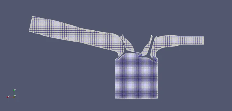
The slice of the engine at -480 degree with mesh:
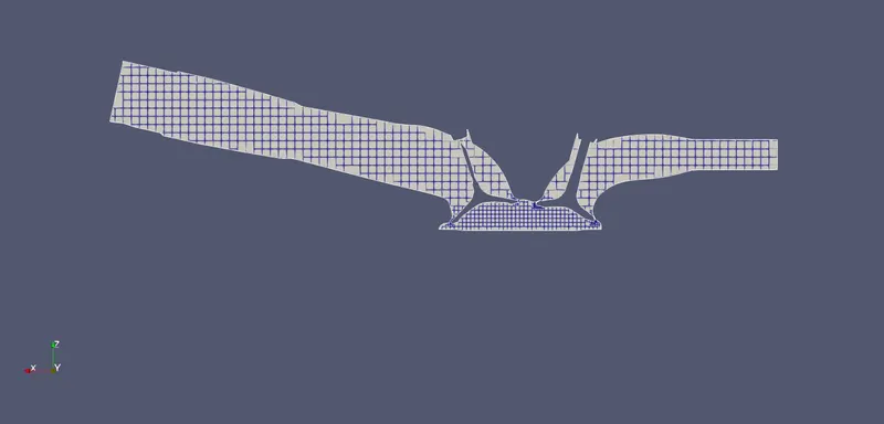
The slice of the engine at -360 degree with mesh:
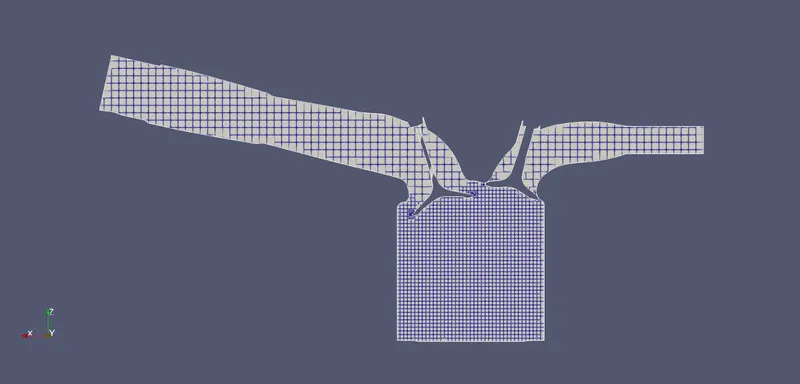
The slice of the engine at -240 degree with mesh:
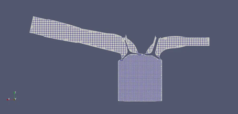
The slice of the engine at -120 degree with mesh:
The slice of the engine at 0 degree with mesh:
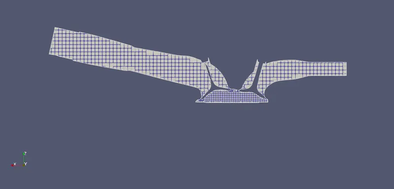
The slice of the engine at 120 degree with mesh:
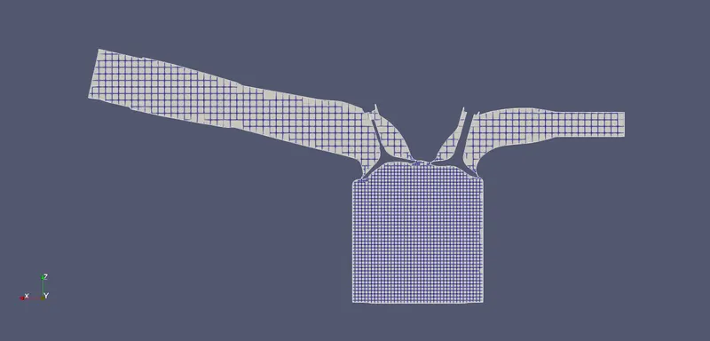
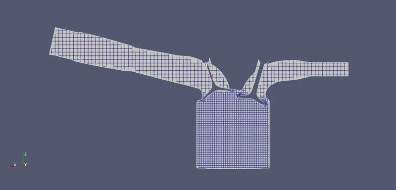
The slice of the engine at 240 degree with mesh:
Conclusions:
We have successfully setup a no hydrodynamic simulation of an IC engine case. Appropriate surface preparation and boundary flagging to setup the case properly. The motion of the piston and valves are captured accurately in the figures and the animation.