Week 9: Project 1 - Surface preparation and Boundary Flagging (PFI)
PFI Engine No-Hydro Simulation
Objective :
To perform surface preparation and boundary flagging task on our IC engine case and setup a NO-Hydro simulation
Boundary flagging:
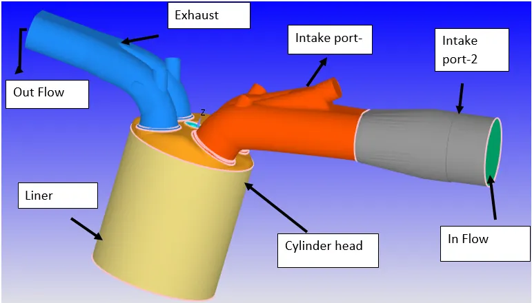
To flag the boundaries, we need to create the fences across the edges of separating boundaries so it eases in the selection of boundaries.
Liner:
Tow edges were selected to mark the fence across the liner edges and the boundary is flagged using the boundary fence method.
Piston:
The piston is flagged by using the boundary fence method.
Cylinder Head:
Boundary fences are created along the 4 edges which separate the region of the ports and spark plug from the cylinder head region and the cylinder head is extracted.
Intake port and Inflow:
The intake port is split into two boundaries and later into two region to separate the boundaries for different initial and boundary conditions. The intake port is where fuel spray and the air is injected. A fences is created using a fence between vertices and appropriate boundaries are flagging from the boundary fence method.
Exhaust port and outflow:
The outflow is flagged using the boundary fence method and the rest of the region as outflow.
Valves:
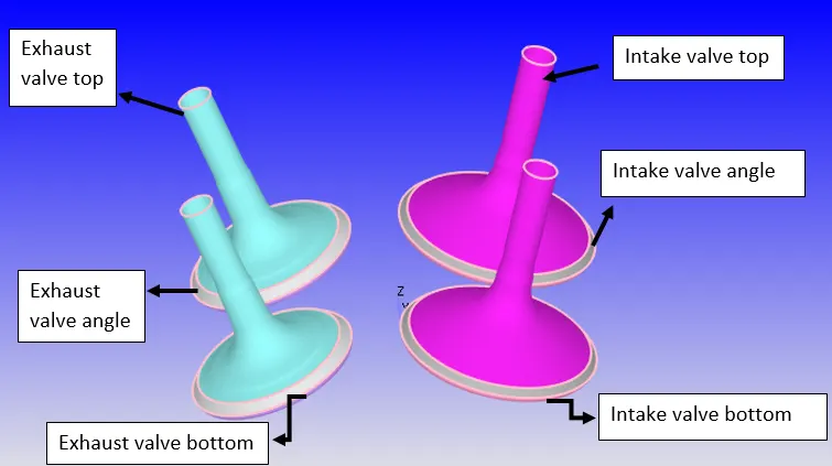
Intake and exhaust ports, liner and cylinder head are hidden and then valves are visible. The valve geometry is flagged into 3 boundaries. This is done to create the events and ease in the creation of disconnect triangles and to assign realistc boundary conditions. Also a translate motion is provided to these valves by loading the motion files.
Spark plug and terminals:
The region where the spark is generated is at a higher temperature than the rest of the spark plug. Hence, two boundaries are necessary to assign appropriate conditions.
Top of valve top assigned to port boundaries:
Due to the translator motion of the valves and set as it is connected ports, during movement of the surface of the ports get distorted. To avoid this distortion, the top of the top valves is assigned to the port boundary.
Regions:
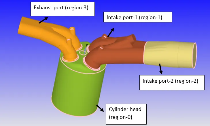
Regions are connected which are used to create events between zones and to initialize the realistic initial conditions in the flow domain.
The figure below shows the boundary assigned to the respective regions:
Initial and boundary conditions:
|
Application type |
Crank angle-based IC engine |
|
Physical parameters |
Cylinder bore: 0.086 |
|
|
Stork: 0.09 |
|
|
Connecting rod length: 0.18 |
|
|
Crank speed: 3000 rpm |
|
|
Piston surface ID: piston |
|
|
Liner ID: linear |
|
|
Head ID: cylinder head |
|
Gas simulation |
Therm.dat |
|
Reaction mechanism |
Mech.dat |
|
Run Parameters |
Solver: transient |
|
|
Type: crank angle-based engine |
|
|
Simulation mode: No-Hydro |
|
Simulation time parameters |
Start time: -480 deg. |
|
|
End time: 240 |
|
Solver parameters |
Solver scheme: PISO |
|
|
Type: density type |
Boundary condition:
|
Piston |
Cylinder head |
Boundary type: wall |
|
|
|
Wall motion: translating |
|
|
|
Surface movement: moving |
|
|
|
Law of the wall: piston motion |
|
|
|
Temperature: 450K (LOW) |
|
liner |
Cylinder head |
Boundary type: wall |
|
|
|
Wall motion: stationary |
|
|
|
Surface movement: fixed (LOW) |
|
|
|
Temperature: 450K (LOW) |
|
Cylinder head |
Cylinder head |
Boundary type: wall |
|
|
|
Wall motion: stationary |
|
|
|
Surface movement: fixed (LOW) |
|
|
|
Temperature: 450K (LOW) |
|
Exhaust valve bottom |
Cylinder head |
Boundary type: wall |
|
|
|
Wall motion: translating |
|
|
|
Surface movement: moving (LOW) |
|
|
|
Temperature: 525K (LOW) |
|
|
|
Profile: exhaust_lift.in |
|
|
|
Minimum lift: 2e-4 |
|
Exhaust valve top |
Exhaust port |
Boundary type: wall |
|
|
|
Wall motion: translating |
|
|
|
Surface movement: moving (LOW) |
|
|
|
Temperature: 525K (LOW) |
|
|
|
Profile: exhaust_lift.in |
|
|
|
Minimum lift: 2e-4 |
|
Exhaust valve angle |
Exhaust port |
Boundary type: wall |
|
|
|
Wall motion: translating |
|
|
|
Surface movement: moving (LOW) |
|
|
|
Temperature: 525K (LOW) |
|
|
|
Profile: exhaust_lift.in |
|
|
|
Minimum lift: 2e-4 |
|
Exhaust port |
Exhaust port |
Boundary type: wall |
|
|
|
Wall motion: stationary |
|
|
|
Surface movement: fixed (LOW) |
|
|
|
Temperature: 500K (LOW) |
|
Out flow |
Exhaust port |
Boundary type: out flow |
|
|
|
Temperature: 800 K |
|
|
|
Pressure: 101325 pa. |
|
|
|
Species: CO2 – 0.192304 |
|
|
|
H2O – 0.088559 |
|
|
|
N2 – 0.719137 |
|
In flow |
Intake port - 2 |
Boundary type: In flow |
|
|
|
Temperature: 363 K |
|
|
|
Pressure: 101325 pa. |
|
|
|
Species: Air |
|
Intake port - 1 |
Intake port - 1 |
Boundary type: wall |
|
|
|
Wall motion: stationary |
|
|
|
Surface movement: fixed (LOW) |
|
|
|
Temperature: 425 K (LOW) |
|
Intake valve top |
Intake port - 1 |
Boundary type: wall |
|
|
|
Wall motion: translating |
|
|
|
Surface movement: moving (LOW) |
|
|
|
Temperature: 480 K (LOW) |
|
|
|
Profile: Intake_lift.in |
|
|
|
Minimum lift: 2e-4 |
|
Intake valve angle |
Intake port - 1 |
Boundary type: wall |
|
|
|
Wall motion: translating |
|
|
|
Surface movement: moving (LOW) |
|
|
|
Temperature: 480K (LOW) |
|
|
|
Profile: intake_lift.in |
|
|
|
Minimum lift: 2e-4 |
|
Intake valve bottom |
Cylinder head |
Boundary type: wall |
|
|
|
Wall motion: translating |
|
|
|
Surface movement: moving (LOW) |
|
|
|
Temperature: 480K (LOW) |
|
|
|
Profile: intake_lift.in |
|
|
|
Minimum lift: 2e-4 |
|
Spark plug terminal |
Cylinder head |
Boundary type: wall |
|
|
|
Wall motion: stationary |
|
|
|
Surface movement: fixed (LOW) |
|
|
|
Temperature: 600K (LOW) |
|
Spark plug |
Cylinder head |
Boundary type: wall |
|
|
|
Wall motion: stationary |
|
|
|
Surface movement: fixed (LOW) |
|
|
|
Temperature: 550K (LOW) |
|
Intake port - 2 |
Intake port - 2 |
Boundary type: wall |
|
|
|
Wall motion: stationary |
|
|
|
Surface movement: fixed (LOW) |
|
|
|
Temperature: 425K (LOW) |
|
|
|
Regions:
|
Cylinder region |
Temperature: 300 |
|
Pressure: 101325 |
|
|
Species: CO2 – 0.192304 |
|
|
H2O – 0.088559 |
|
|
N2 – 0.719137 |
|
|
Intake port – 1 |
Temperature: 390 |
|
|
Pressure: 101325 |
|
|
Species: O2 – 0.2057 |
|
|
N2 – 0.77292 |
|
|
IC8H18 – 0.025508 |
|
Intake port – 2 |
Temperature: 370 |
|
|
Pressure: 101325 |
|
|
Species: O2 – 0.23 |
|
|
N2 – 0.77 |
|
Exhaust port |
Temperature: 1360 |
|
|
Pressure: 185731 |
|
|
Species: CO2 – 0.192304 |
|
|
H2O – 0.088559 |
|
|
N2 – 0.719137 |
Events:
CYCLIC
|
Region A |
Region B |
Events |
|
Cylinder head |
Intake port - 1 |
Valve |
|
Cylinder head |
exhaust port |
Valve |
PERMANENT
|
Region A |
Region B |
Events |
|
Intake port – 1 |
Intake port - 2 |
open |
Mesh grid:
Here the base grid of 0.004mm is used along with the fixed embedding for the intake and exhaust valve angle scale of 3 and 1 embedding layer is used with permanent mode. Whereas, for the cylinder region and zones next to the vales in the ports a cylinder entity is used with a scale of 2 &1 respectively.
Conclusion:
Following all the step described in our procedure and running the no hydro simulation we will end with the following animation shown below describing our valve movements defined by their timing profile