Week 9 - Project_1 - Door Trim Lower with Engineering Features
Objectives :
Create the Door Trim Plastic component through the given Class-A surface. To begin with, the tooling axis for the given Class-A Surface should be created meeting the requirements of the draft angle and at the end perform the Draft analysis on the model.
Creation of Tooling Axis :
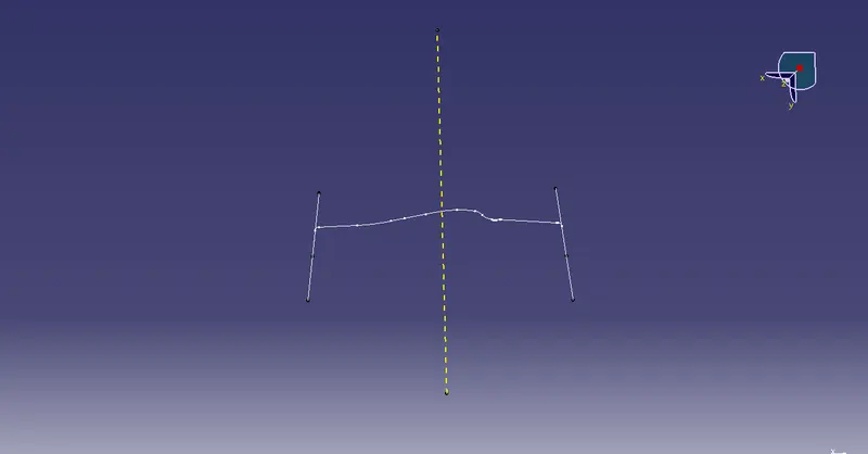
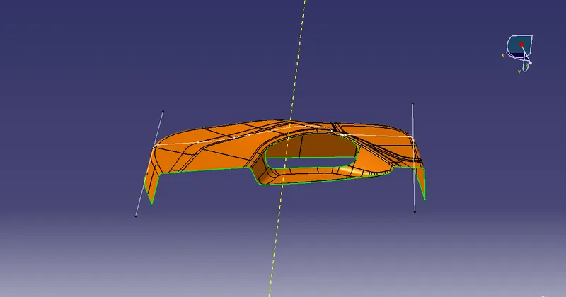
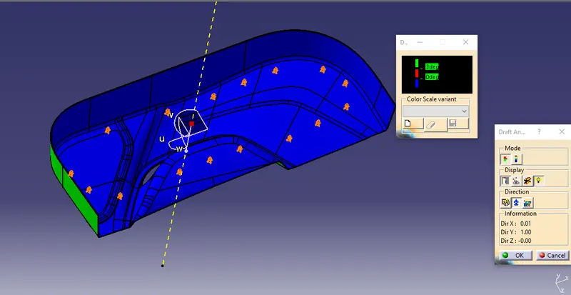
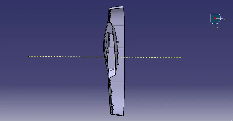
To create the tooling axis, I extracted a surface from class A and created a point in the middle of the surface by using the point command and created a line at that point through the x-axis. Now, I performed a draft analysis check from that line whether the created tooling axis is in the correct position or not. If in the draft, analysis check the surface highlighted with green colour on both sides of the surface the tooling axis is in the correct position and direction.
Tooling axis:
DRAFT ANALYSIS FOR CLASS A SURFACE:
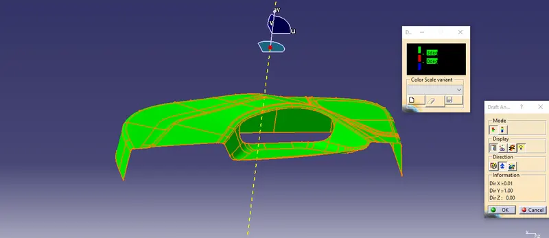
We do perform the draft analysis check for class A surface before we make solid and creation of B-side features. Initially I align the compass to the tooling axis and I gave a 3deg draft angle for the green colour in the colour bar. If the surface is highlighted in green colour the draft angle is given properly for class A surface. If the class A surface is not highlighted fully in green colour, that might be the reason for the draft angle of the class A surface.
Construction of class B & C Surface
Construction of class B surface
- Extract the class A surface for the given thickness of 2.5mm inward
- After extraction check the surface for patches
- If any patches were found clear them first
- Repair the surface using the suitable methods
- Using join method in remove mode sub elements to remove remove the surface with patches
- Then using disassemble seperate the surface into 4 domains
- Now using boundary,extrapolation&trim command repair the surfaces
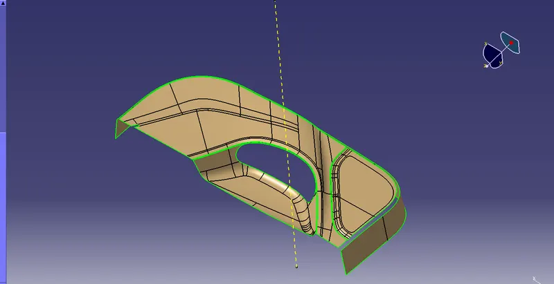
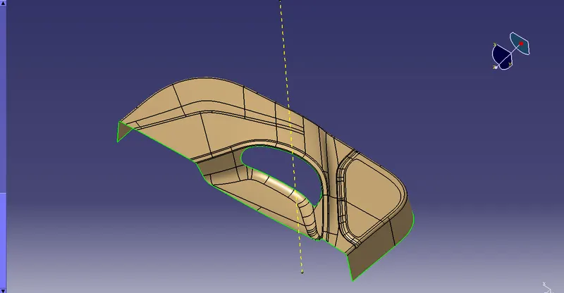
Construction of Class C surface
- At First Create a boundry in the center part of the Class A Surface
- Then using the sweep command create a sweep with the angle of 90deg and the boundary which we have created as the guide curve
- Then to reduce error while making sweep create seperate boundaries and then sweep
- so that it can clear the draft analysis
- Join all the patches in the surface we have created
- Join the created class C with class A
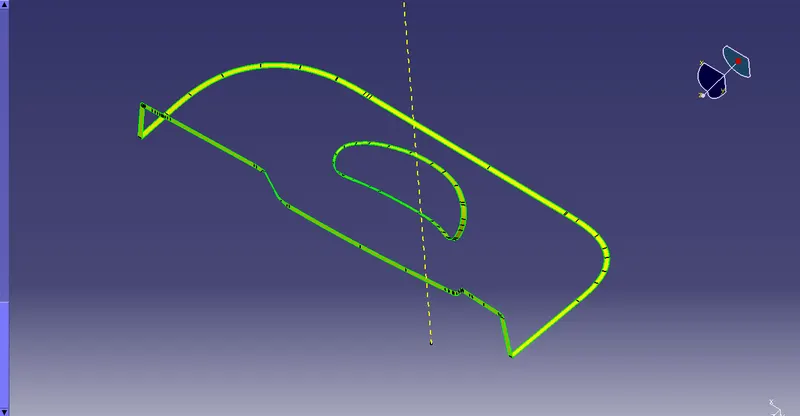
Final trim
- As for the final trim join class A and Class C surface
- And then trim the Class A + C surface with Class B surface
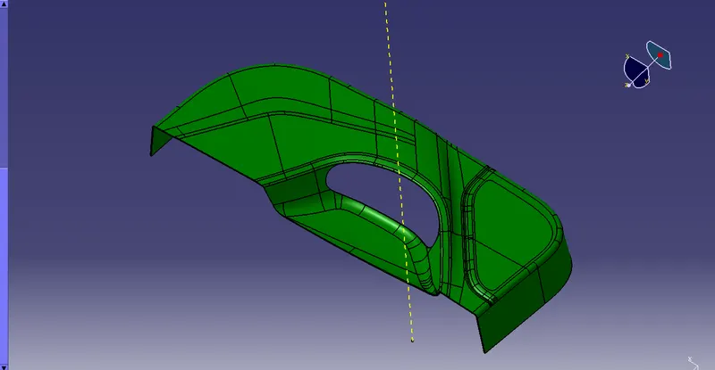
CREATION OF LOCATORS:
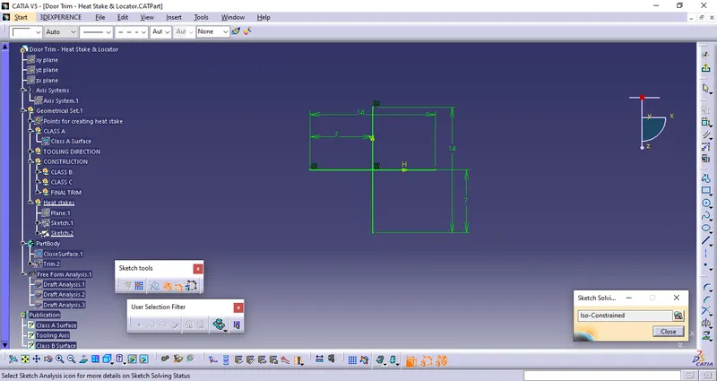
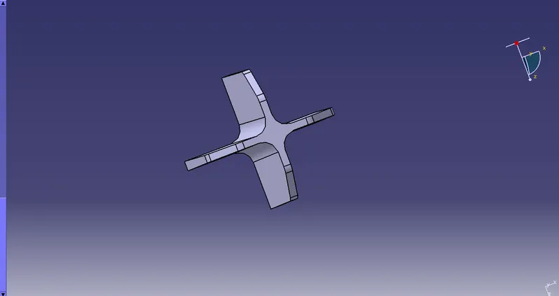
To create the locators, I created a sketch on the body. After creating the sketch, I pad it 20mm in height and thicken it to 1.3mm and I drafted it with 0.5deg in the direction of the tooling axis. I gave 3mm of chamfer with 45deg of inclination and after I gave a fillet of 0.25mm radius.
4-way locator:
CREATION OF HEAT STAKES:
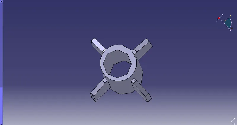
To create the heat stakes, I draw a sketch on the surface. After the creation of the sketch, I pad it to 18mm height and I gave a draft angle of 0.5deg on both sides (inside and outside) and then I gave a fillet with a 0.25mm radius. After creating the heat stake, I created the ribs for supporting purposes. To create the ribs, I draw a sketch and padded it to 12mm in height and 1mm in thickness. After padding the ribs, I drafted 0.5deg in the tooling asix direction and filleted it with a 0.25mm radius. Finally, I union trim the ribs with a heat stake to remove the ribs, which are present inside the heat stakes.
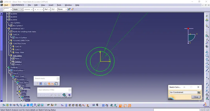
HEAT STAKES WITH SUPPORTING RIBS
DRAFT ANALYSIS OF FINAL PRODUCT
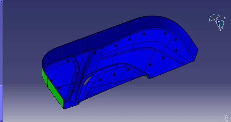
ISOMETRI VIEW
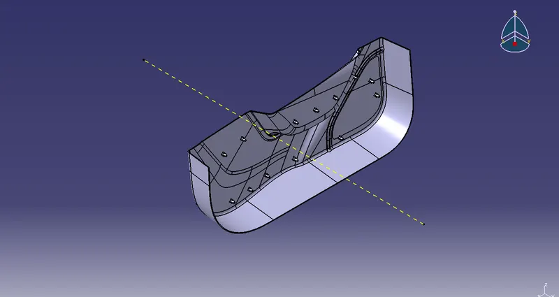
FRONT VIEW
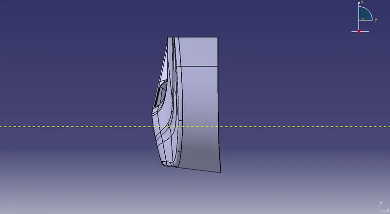
TOP VIEW
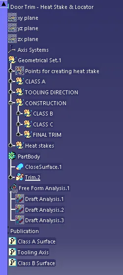
GEOMETRICAL TREE