Week 9 - Project 1 - Door Trim Lower with Engineering Features
AIM :
To create the Door Trim Lower Plastic component through the given Class-A surface, take the thickness of the component as 2.5 mm. To begin with, the tooling axis for the given Class-A Surface should be created meeting the requirements of the draft angle and at the end perform the Draft analysis on the model.
Create the Heat Stakes, Locators, Dog House, & Ribs considering the design rules.
REPORT :
This report demonstrates the design of an Automotive Plastic Component – Door Trim (Plastic) with Engineering features such as Heat Stakes, Locators, Dog House, & Ribs using industry principles i.e. Draft angles, Draft Analysis, Determining and implementing of Tooling Axis, Class A, Class B, and Class C surfaces. The component is designed using Surface Design and Solid Design techniques in CATIA V5.
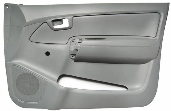
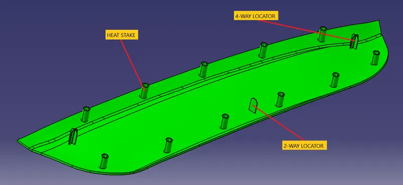
Fig : Final Component (Door Trim) with the location of Engineering Features.
OBJECTIVE :
- Conduct a Draft Analysis on the Class A surface for the Door Trim Plastic for determining the appropriate Tooling Axis.
- Creation of other surfaces i.e. B & C Surface for creating a solid component
- Performing the final Draft analysis for the inspection and checking if all the features are above the Nominal Drafting for the creation of the Solid Model.
THEORY :
The terms are briefly explained below:
1) DRAFT :
The draft is an angular tapering given at the design stage to every Plastic Component that has to be manufactured. It is given in the direction of the Mold Movement. The Draft allows the parts to release easily from the mold without creating friction between the surface of the component and the core and cavity plates.
When a Plastic component cools down inside the mold, its natural tendency of it is to shrink and attach to the core or cavity half. The movement of the mold opening causes friction on the walls of the component as well as the core/cavity blocks. This reduces the life of the mold as well as the component itself. The component may also have a rough surface finish as well as a weak structure due to this. This problem can be solved by giving a draft to the component.
Most applications require minimum draft angles of around 0.5º to 1º however, 3º draft angles are widely accepted for cost-saving purposes. 7º Draft angles are given to textured surfaces like Instrument Panels. Minimum possible draft angles are given to screw bosses, ribs, and stiffeners due to their critical nature.
2) DRAFT ANALYSIS :
Draft Analysis is a tool in CATIA that identifies the zones which deviate from the specified values of angles along a defined draft direction using color codes. Draft analysis is the first step performed after receiving the Class A of the component. Draft analysis should be passed in order to make the plastic component manufacturable. Acceptable draft angles are used as a range for draft analysis.
For Analyzing the Draft of the Class A Surface:-
- Change View Mode Customization to Material mode
- Go to INSERT ----> ANALYSIS ----> FEATURE DRAFT ANALYSIS.
- Select the compass from the dialog box, and move the compass to the Tooling Axis.
- Click on the surface to apply the color region on the component.
- Change the range to 0º to 2.9º. Apply the settings as shown in Figure.
- As shown the target area has a 0º draft angle which was the concerned face since it's a flat surface.
- Thus, it passes the criteria of having a suitable draft and the Class A can be further designed into a solid plastic component and manufactured.
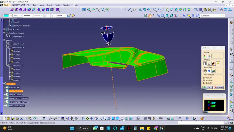
Fig : Draft Analysis for Class A Surface
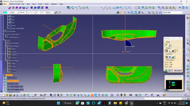
Fig : Multi-section view
3) TOOLING AXIS :
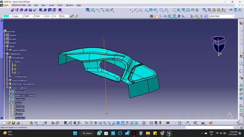
The tooling Axis is the direction in which the Mold opens and closes. Part Drafts are given along this axis. Identify faces that can potentially create problems while manufacturing. Surfaces at angles along a desired Tooling Axis. Extract a plain surface and create a point on its center for Axis system creation. In this case, X-axis can be a possible Tooling Axis Direction.
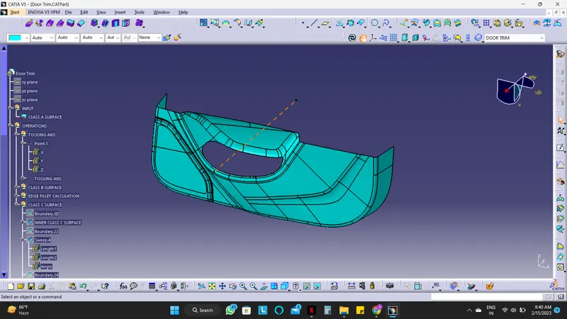
4) CLASS A SURFACE :
In automotive design, a class A surface is any of a set of freeform surfaces of high efficiency and quality. It is the visible aesthetic surface of any automotive component. Class A surface refers to those surfaces which are visible and abide by the physical meaning of a product. This classification is primarily used in the automotive and increasingly in the consumer goods industry. It is a requirement where aesthetics has a significant contribution. For this reason, the exterior of automobiles is deemed Class-A.
5) CLASS B SURFACE :
Class B surfaces are Engineering Surfaces that are invisible to the eyes or often on the back side of the Class A surfaces. It is mainly the thickness of the component or Class A. These surfaces need to be designed as per the Class A surface i.e., the continuity, thickness of the component, functionality, etc should be maintained. These surfaces include the main engineering features such as Screw bosses, Ribs, Snaps, Stiffeners, and fixations. B surfaces also do not contain any aesthetic styling content and textures since it is not visible to the eyes.
Below fig shows both Class A & Class B surfaces.
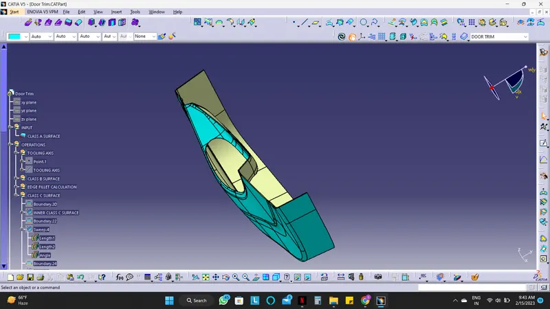
The light blue colored surface is the Class A surface & grey colored surface is the Class B surface.
6) CLASS C SURFACE :
Class C surfaces are connectors between Class A and B surfaces. This surface connects both A and B surfaces along the Tooling Axis. It contains the draft as per the design. It is basically the thickened surface between both A and B surfaces.
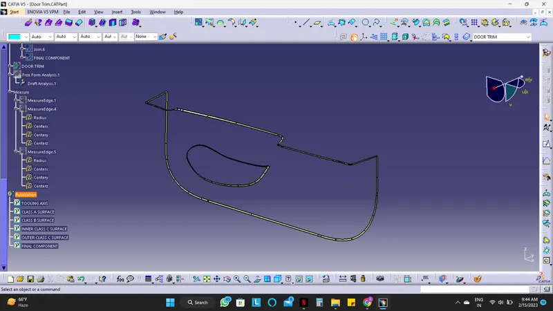
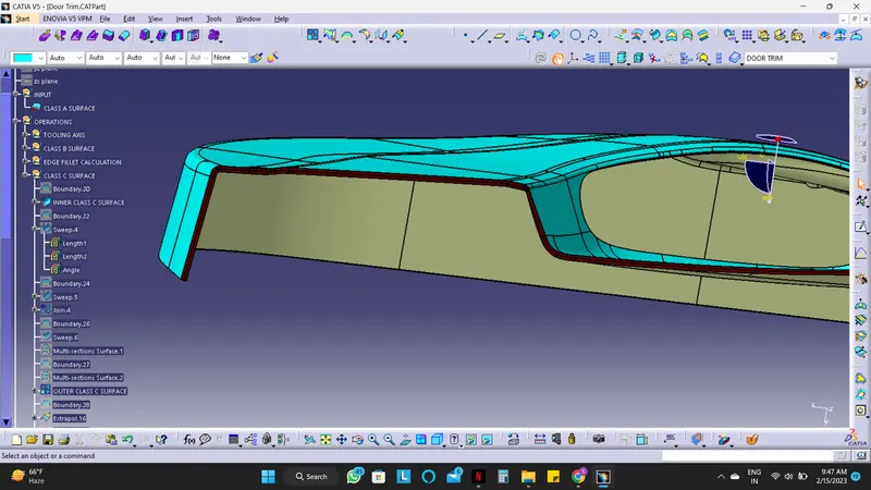
The light blue colored surface is the Class A surface, the Grey colored surface is the Class B surface & the Dark brown colored surface is the Class C surface
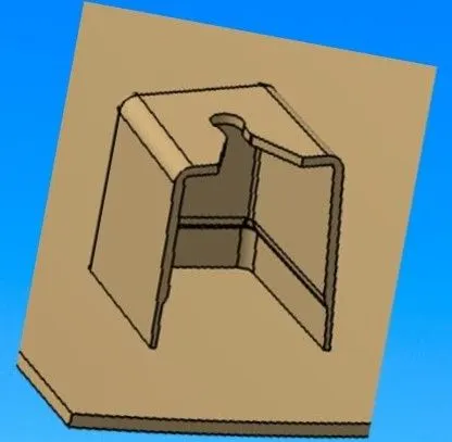
7) DOG HOUSE :
The dog house is an engineering feature used in the plastic trim design. Dog houses are used as supporting features. Sometimes other engineering features like snaps, locators, Screw bosses, etc. are mounded on them to increase their strength. Dog houses are subjected to draft analysis to prevent breakage of the component during ejection from mould cavity. Dog house and other engineering components are built on B-surface.
8) LOCATORS :
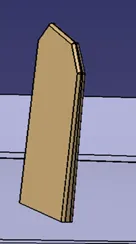
Locators are mainly used to Arrest the Degrees of Freedom of the Plastic Component. Usually there are 2-way and 4-way Locators. It also supports the Position of Plastic Component While Assembly or Joining of Components.
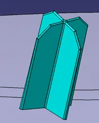
A 2-way locating pin restricts motion along 1 axis (or 2 degrees of Freedom), like a round pin in a slot. Likewise, a 4-way pin restricts 4 degrees of freedom along 2 axes. A round locating pin located concentrically in a hole is a common application of a 4-way pin, and helps to further secure the piece.
4-way mean you prevent movement at 2 axes (+X, -X, +Y and -Y) on the plane. Generally, you have cylindrical pin on the fixture and circular hole at the workpiece part.
9) HEAT STAKES :
Manufacturing operations currently use many different combinations of attachment methods to keep components together. Common fasteners such as bolts, screws, and rivets can be used to form permanent attachments, but there are attachment methods that don’t require secondary hardware. One of those methods is heat staking, which doesn’t require additional fasteners. Heat staking also known as Thermoplastic staking is the process of joining two Plastic Components together.
OPERATIONS :
A. Creation of Final Component without Engineering Features :
1) Creation of B surface :
- Offset the relevant surfaces from Class-A surface, the offset length is 2.5 mm since the thickness is 2.5 mm.
- Here are some patches which are not offset as required, these patches must be filled properly with their respective dimensions.
- The patches are on the 3 edges of the Door trim (shown in below figs.)
- The offset of these surfaces is shown below.
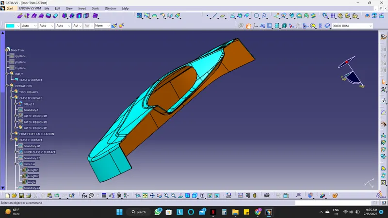
The light blue colored surface is the Class A surface & orange colored surface is the offset surface.
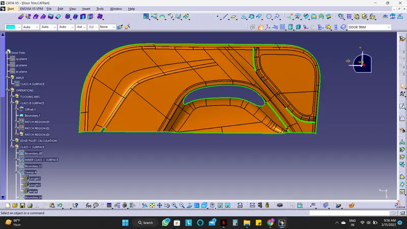
As you can see in the above fig. there are 3 patches on the door trim (1 on the left side and the other 2 on the right side)
-------> Starting with the creation of Patch Region 01.
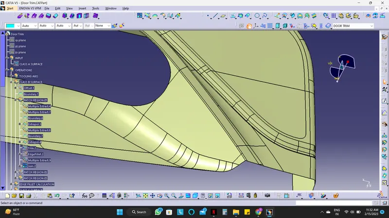
The Patch region 01 is visible properly in the fig. shown below
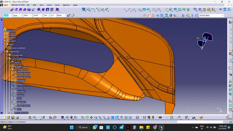
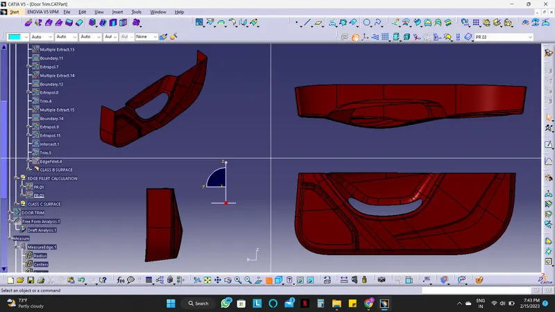
- Extract the required portions i.e. the whole door trim except the patch region 01 (edges) using "Multiple Extract" and keep the complementary mode on. The Complementary mode helps in the selection of the surface which should not be extracted very easily.
- Now Extract the horizontal surface, and the vertical surface one by one using "Multiple Extract" which is connected with each other through the fillets.
- After extraction give a boundary to the surface with limits.
- Extrapolate the surface on the boundary with the appropriate length.
- Where these horizontal and vertical surfaces of the door trim intersect with each other use the Trim command to trim as shown in below fig.
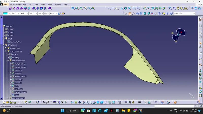
- Measure the edge fillet radius of any edge of the grill and give the edge fillet.
- Creating fillets.
- Create Fillets while maintaining the part thickness between the Class A and Class B surfaces.
- The Value of the Fillet is given by the equation (B surface fillet = A surface fillet +/- Thickness of the Part).
- The sign + or – must be decided so as to maintain the part thickness which in this case is 2.5mm.
- Now join the Offset and the Patch region 01 Surfaces with each other.
- Patch region 01 is completed.
-------> Now the creation of Patch Region 02.
The Patch region 02 is visible properly in the fig. shown below
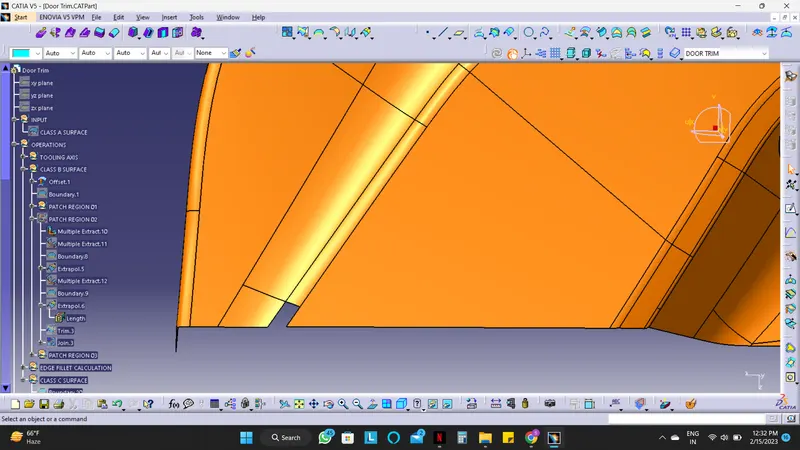
- Here steps for creating Patch region 02 will be same as the patch region 01, Multiple extraction with complementary mode on, Extraction of the 2 surfaces where fillet joins them, boundary, extrapolation, and Trim.
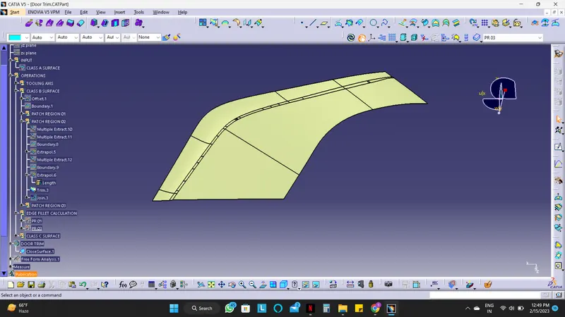
- Creating fillets.
- Create Fillets while maintaining the part thickness between the Class A and Class B surfaces.
- The Value of the Fillet is given by the equation (B surface fillet = A surface fillet +/- Thickness of the Part).
- The sign + or – must be decided so as to maintain the part thickness which in this case is 2.5mm.
- The Patch region 02 is completed.
-------> Now the creation of Patch Region 03.
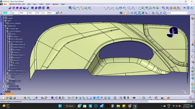
The Patch region 03 is visible properly in the fig. shown below
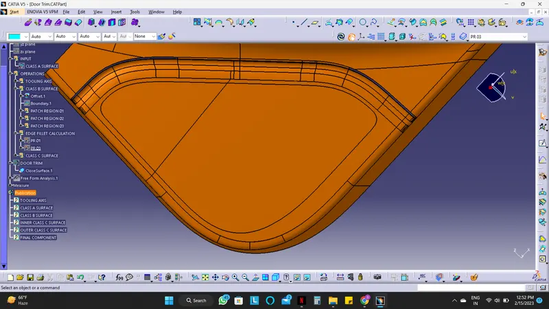
- Here the methodology is the same just the process is repeated and Long.
- Extract all the surfaces but in 3 parts as shown below in fig. This partition in 3 parts is because of the edge fillet which joins them together. Different patches are shown with different colors (green, maroon, yellow).
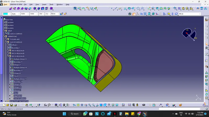
- Give a boundary and extrapolate any 2 surfaces, here I used the green and maroon surface first.
- Trim the surface with each other. Now we have 2 surfaces the lower vertical surface (yellow), and the trimmed surface (light blue) as shown in fig below.
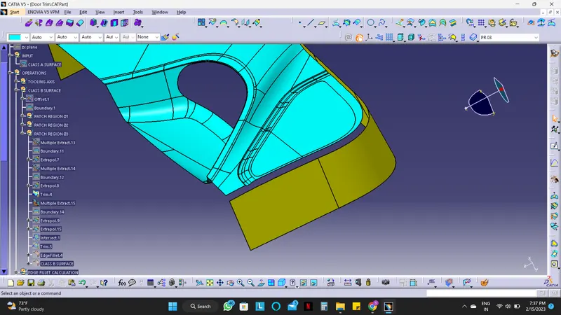
- Now repeat the methodology, give boundary to both the surface extrapolate, and then trim with each other.
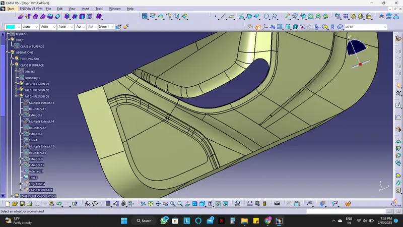
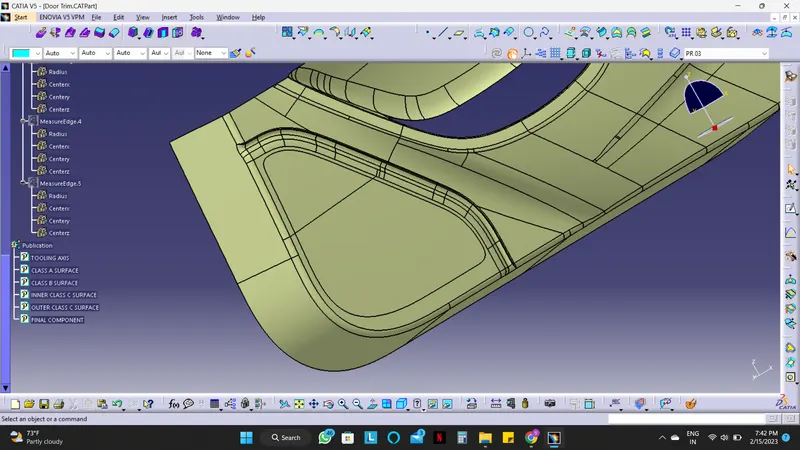
- Here we got the whole surface except the edges are not filleted. Measure the edge fillet radius of both the edge of the door trim and give the edge fillet.
- Creating fillets.
- Create Fillets while maintaining the part thickness between the Class A and Class B surfaces.
- The Value of the Fillet is given by the equation (B surface fillet = A surface fillet +/- Thickness of the Part).
- The sign + or – must be decided so as to maintain the part thickness which in this case is 2.5mm.
- Patch region 03 is completed.
Here the Class B surface is created.
2) Creation of C surface :
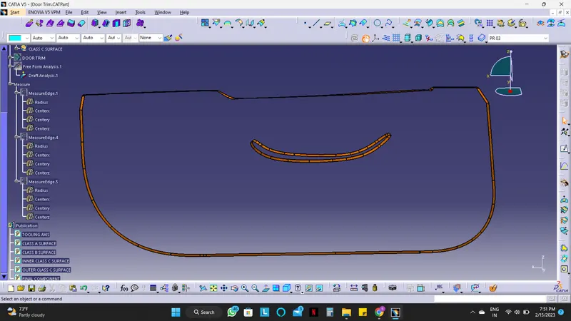
- Using the Boundary feature, the surface edges of Class A Surface and create boundaries on two surface edges, i.e. the inside hollow surface and the outer edge.
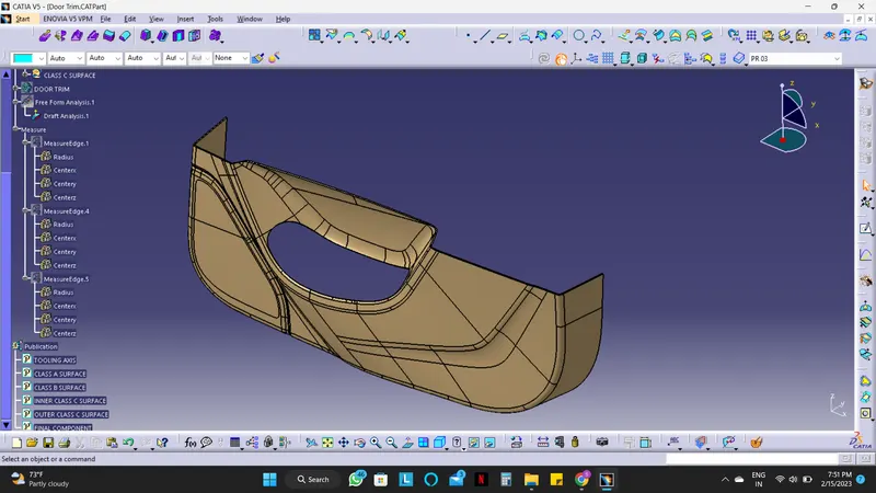
- The sweep option is carried on the boundary lines to create a draft length extension (5mm) and draft angle (87°). Here instead of taking 90°, we have to take 87° because of some inclination and for trimming with the Class B surface.
- After the Sweep Operation, the Class B surface and the sweep surface are trimmed with each other in order to create the Class C surface.
- Finally, Join the Class A Surface and the trimmed Surface to create the Final component.
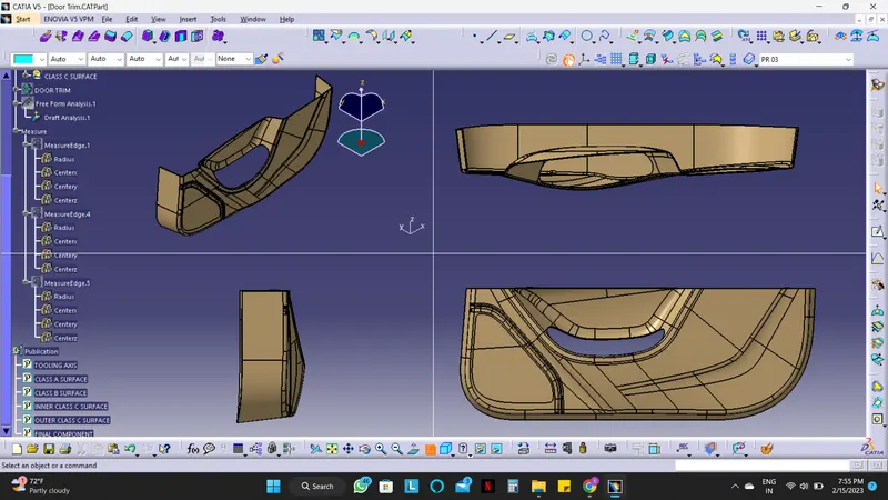
Draft Analysis on the Closed Surface :
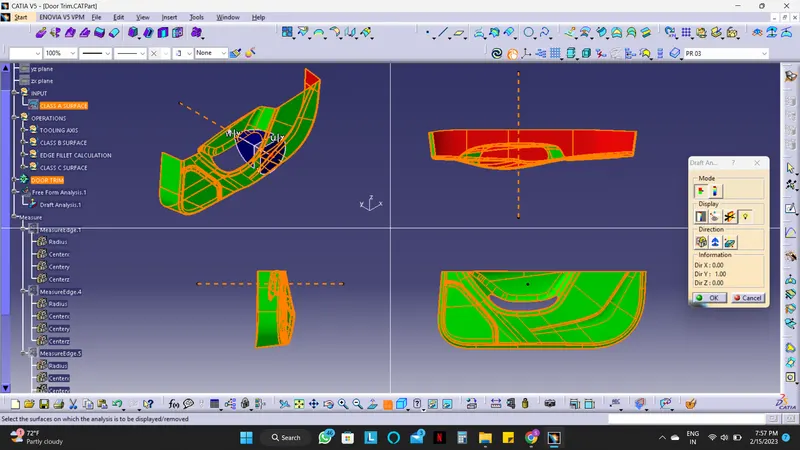
Screenshots of the solid model with the proper color code of the draft angle in various orientations (Isometric, Front, Side, and Top View)
B. Creation of Engineering Features on the created Lower Door Trim :
1) Creation of Heat Stakes and Supporting Ribs :
- Firstly draw a sketch of the circular portion and the supporting ribs using the Position Sketch and reference plane.
- Use the points for sketching which are provided.
- Created a solid Body in the part Design by using the commands Pad and thickness option (only while creating supporting ribs) with appropriate dimensions.
- Now give the Draft and fillet as required.
Dimensions for Heat Stake :
| 1. | Outer Circle | 08 mm Diameter |
| 2. | Inner Circle | 05 mm Diameter |
| 3. | Pad (First Limit) | 18 mm |
| 4. | Pad (Second Limit) | 02 mm |
| 5. | Draft (inner & outer) | 0.5 deg |
| 6. | Fillet (on the top surface) | 0.5 mm |
Dimensions for Supporting Ribs :
| 1. | Vertical line | 13 mm |
| 2. | Horizontal line | 13 mm |
| 3. | Pad (First Limit) | 12 mm |
| 4. | Thickness (both sides) | 0.5 mm |
| 5. | Pad (Second Limit) | 02 mm |
| 6. | Draft (12 faces) | 0.5 deg |
| 7. | Chamfer (4 faces) | 1.5 mm & 45 deg |
| 8. | Fillet (on the edges of chamfer) | 01 mm |
| 9. | Fillet (on the edges of ribs) | 0.25 mm |
- Both the elements are created with a closed body, Now union trim with each other.
- Here 1 Heat stake with supporting ribs is ready and multiple bodies are left to create.
- For creating multiple bodies of created heat stake, copy the union-trimmed heat stake and paste it with special link as many times as required.
- Now translate them to the points which are provided.
- Create a body where all these heat stakes can be assembled and union trim this body with the main Lower door trim body.
- Hence final Heat stakes with supporting ribs are obtained.
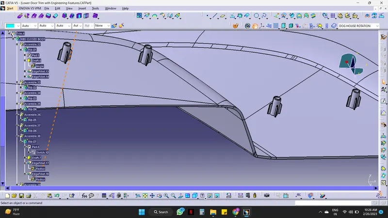
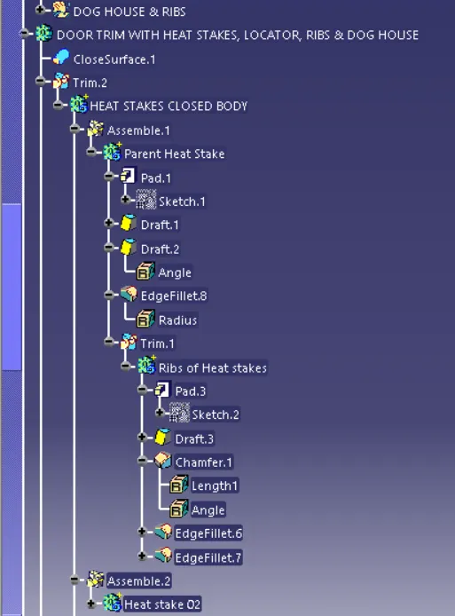
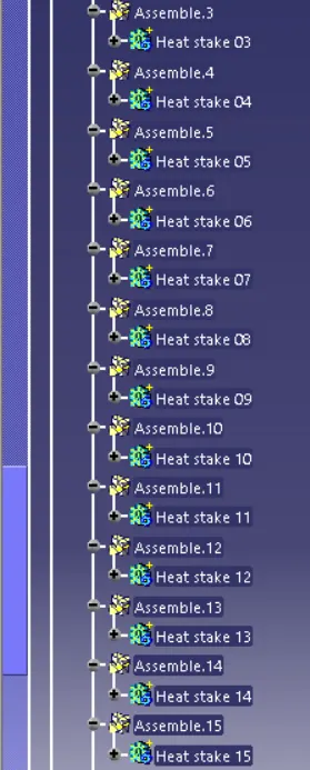
TREE STRUCTURE FOR HEAT STAKES WITH SUPPORTING RIBS
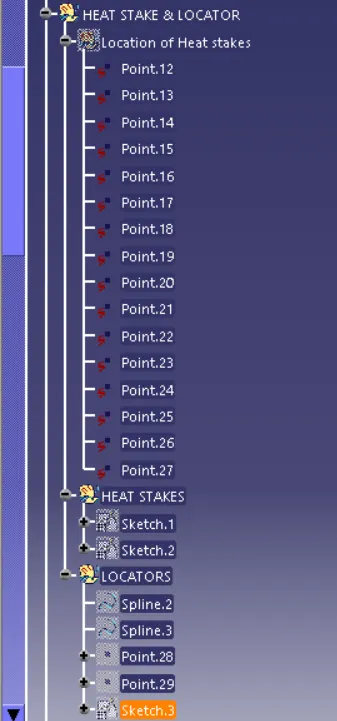

2) Creation of Locators :
- Use the spline command and point command with the middle point option to draw a line and point for locating the Locator position.
- Draw a sketch for the supporting ribs using the Position Sketch and reference plane.
- Created a solid Body with thickness in the part Design by using the commands Pad with appropriate dimensions.
Dimensions for Locator :
| 1. | Vertical line | 15 mm |
| 2. | Horizontal line | 15 mm |
| 3. | Pad (First Limit) | 20 mm |
| 4. | Thickness (both sides) | 0.7 mm |
| 5. | Pad (Second Limit) | 02 mm |
| 6. | Chamfer (4 faces) | 05 mm & 45 deg |
| 7. | Draft (8 faces) | 0.5 deg |
| 8. | Fillet (on the edges of chamfer) | 0.5 mm |
| 9. | Fillet (on the edges of the locator) | 0.25 mm |
- Here 1 Locator is created with a closed body and 1 more is left to create.
- For creating 1 more locator, copy the created locator and paste it with special link.
- Now translate it to the point which is created using spline and point.
- Create a body where these 2 locators can be assembled and union trim this body with the main Lower door trim body.
- Hence final Locators are obtained.
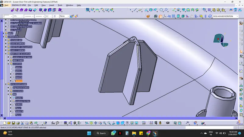
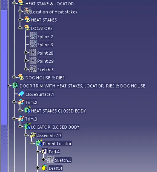
TREE STRUCTURE FOR LOCATORS.
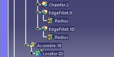
3) Creation of Dog House :
- Draw a line using the spline command and create points where the dog houses are required using the middle point option.
- Create a plane on the point where the dog house is straight at 90 deg, and draw a sketch for the Dog House using the Position Sketch and created a reference plane.
- Use the sweep command for creating the walls of the dog house.
- Draw a line on the base of the dog house and extrude it. This extruded surface will help us in creating the top surface and the core. Offset this surface with 2 appropriate lengths for the top surface and core.
- Trim the offset with walls for creating the top surface. Here the inner surface of the Dog House is created.
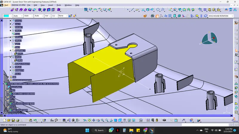
The yellow-colored surface is the inner surface of the Dog House
- Now extrude the same line Vertically which is created on the Base. Offset it with the appropriate length for creating the Front and back of the Dog house.
- Trim and split as required with the inner surface of the dog house.
- Give edge fillet to the inner surface.
- Create a body and give thickness to the inner surface. Give Draft to the surface as required.
- Now extract the inner surface and offset it with the appropriate length for creation on the core.
- Extrapolate and trim it as required. Hence the core is obtained.
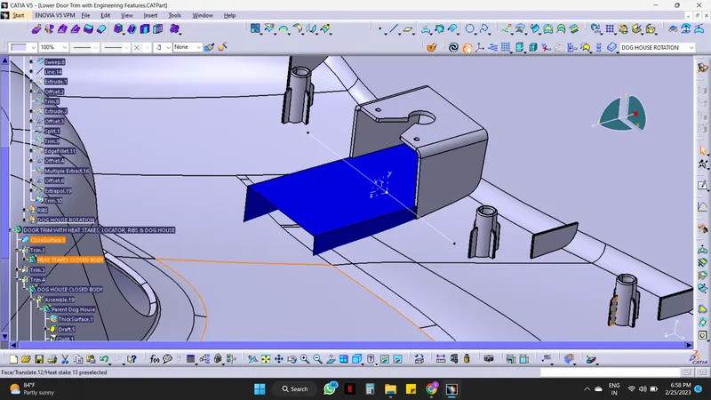
The dark blue colored surface is the core of the Dog House.
- Use the split command to cut the core surface from the thickened surface.
- Now draw a sketch for push pins on the top surface of the dog house and pocket it.
- Give edges as required. Hence Dog House is created.
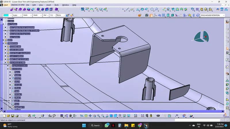
- Here 1 Dog House is created with a closed body and 2 more are left to create.
- For creating 2 more Dog Houses, copy the created Dog House and paste it with special link.
- Now translate it to the point which is created using spline and point.
- Create a body where these 2 locators can be assembled and use rotate command for rotation left one will be for 30 deg and the right one will be 330 deg.
- Union trim this body with the main Lower door trim body. Hence final Dog House is obtained.
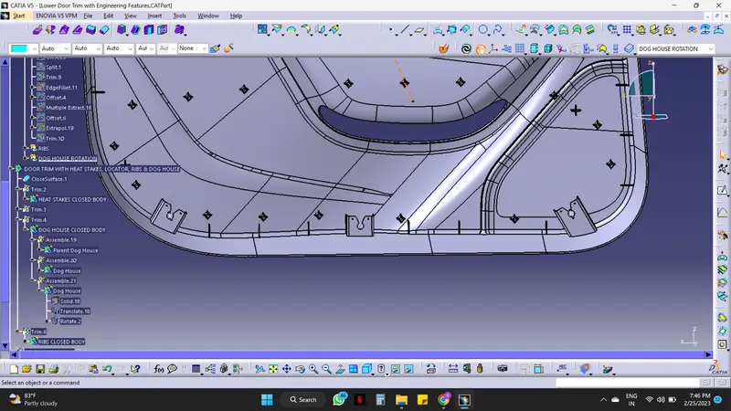
TREE STRUCTURE FOR DOG HOUSE.
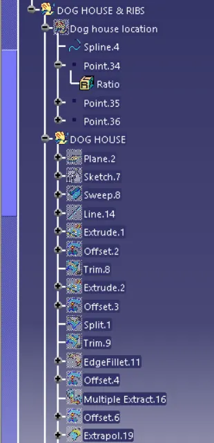
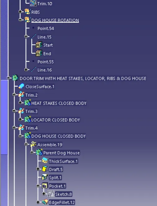
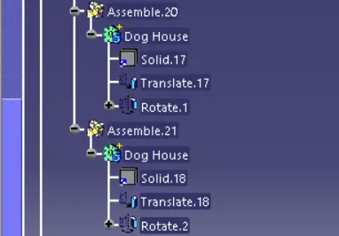
4) Creation of RIBS :
- Firstly draw a parallel curve and multiple points on that curve using points and plane repetition command for getting the exact location of the ribs.
- Select the points where the ribs are required and delete the other points.
- Draw sketches of the ribs using the Position Sketch and create a reference plane. Here draw 3 sketches i.e. for the left, right, and bottom sides.
- Now pad the sketches, give the draft, and the edge fillet with appropriate dimensions.
Dimensions for Supporting Ribs :
| 1. | Vertical line (for all 3 sketches) | 40 mm |
| 2. | Pad (for bottom ribs) | 40 mm |
| 3. | Pad (for left side ribs) | 16.5 mm |
| 4. | Pad (for right side ribs) | 9 mm |
| 5. | Thickness (both sides) | 0.5 mm |
| 6. | Draft (3 faces) | 0.5 deg |
| 7. | Fillet | 0.25 mm |
- Here 3 Ribs with the closed body are created and multiple bodies are left to create.
- For creating multiple bodies of created Ribs, copy the Ribs and paste them with special link as many times as required.
- Now translate them to the points which are created.
- Create a body where all these heat stakes can be assembled and union trim this body with the main Lower door trim body.
- Hence final Ribs are obtained.
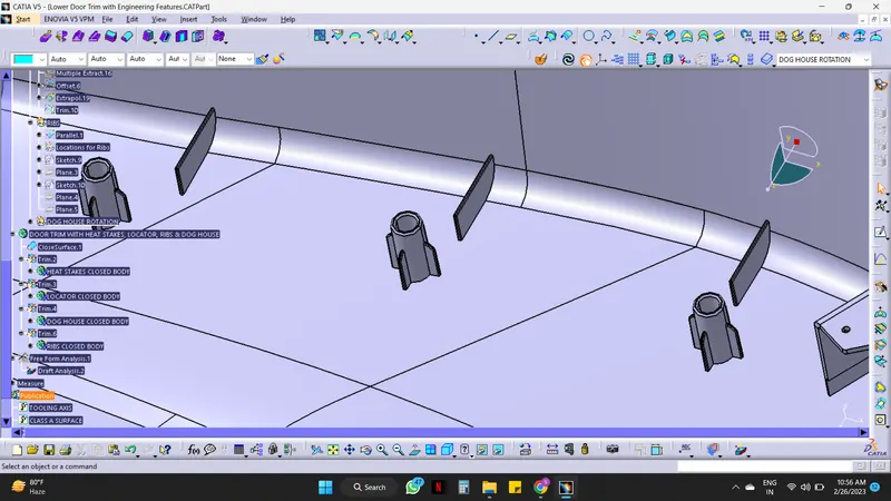
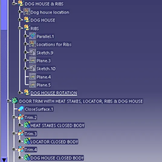
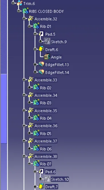
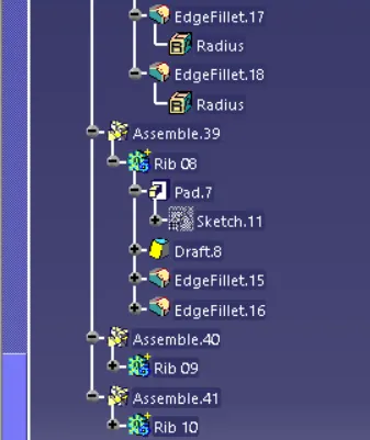
TREE STRUCTURE FOR RIBS.
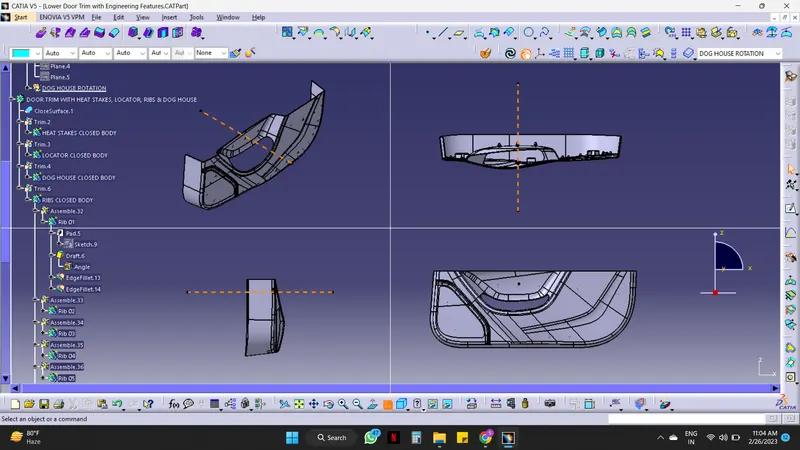
Draft Analysis on the Lower Door Trim with Engineering Features :
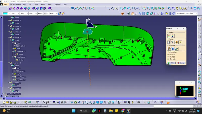
Screenshots of the solid model in various orientations (Isometric, Front, Side, and Top View)
CONCLUSION:
The Design of the Automotive Plastic Component – Lower Door Trim with engineering features from Class A is completed using concepts of Draft angle, Draft Analysis for Class A & Final enclosed surface, Tooling Axis creation & Implementation, Class B & Class C creation, Heat stakes with supporting ribs, Locators, Dog house, and Ribs.