Week 9 - Project 1 - Door Trim Lower with Engineering Features
DOOR TRIM LOWER
Aim: To Create the Door trim lower component through the given Class-A surface.
Objectives:
- Creation of Tooling axis with appropriate draft angle.
- Creation of other class B and C surfaces for creating a solid component.
- Perform Draft analysis on Class A surface and Solid model hence created.
- Creation of heat stake and locators and final draft analysis
Draft
The draft is the amount of taper for molded or cast parts perpendicular to the parting. line. Draft angles are a design consideration that makes it much easier for a part to release cleanly from a mold. A draft angle is calculated as a degree measurement (or, less often, an inch or millimeter measurement) from the vertical axis of a mold, and it helps account for thermoplastic shrinkage, a practical reality of the injection molding process for most materials.
Draft angles are generally a requirement of injection molding design (though there are a select few soft materials, like nylon, that can get away with draft angles of zero). The draft should be a part of the design for manufacture, and all stakeholders and contributors should be aware of its need at the outset of the design process. This includes product designers, design engineers etc. and this allows considerations for design requirements to be taken into account. Any draft is always better than no draft.
Importance of Draft:
By accounting for thermoplastic shrinkage during the cooling process, draft angles significantly reduce friction between the finished, cooled part and the side of the mold, Not only does this create a much easier release process, but it also offers several other benefits, depending on the design of the part which is as follows:
- Reduces the chance of damage to the part due to friction during the release.
- Reduces wear and tear and chances of damage to the mold.
- Ensures a uniform, smooth, unscratched finish when required. • Ensures the integrity and uniformity of other surface finishes and textures.
- Reduces overall cooling time by lessening or eliminating the need for unconventional ejection setups.
- Most, if not all, of these benefits, offer either direct or indirect overall production cost reductions.
Creation of Solid model:
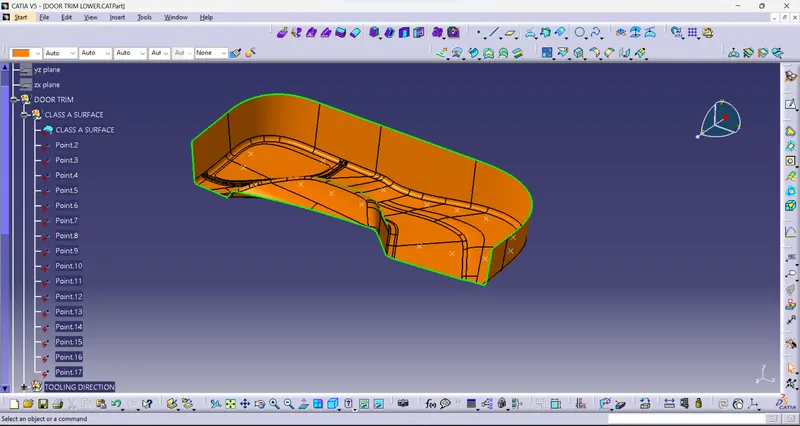
The image below shows the given class A surface for which a solid model is to be created.
Tooling Axis creation:
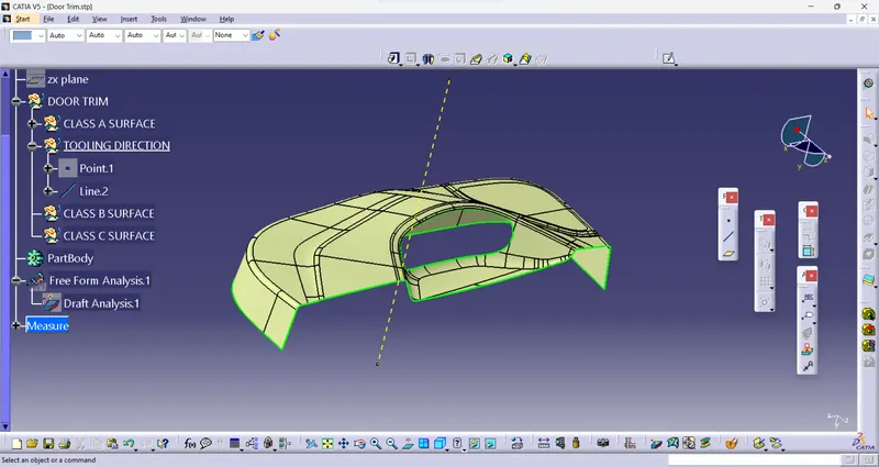
It is defined as the direction in which the core and cavity open. Selection of the direction of the tooling axis depends on the ease at which components can be easily ejected.
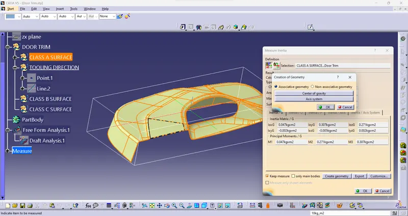
Visualizing the component in 3 axes X, Y and Z most of the part in visualized in Y direction now create a line on a surface with point and stretch the line in y direction for certain length where point is to be created at center of gravity of the class A surface model.
After creating draft analysis is to done for feasibility check
Draft Analysis
Same steps are followed to get the draft analysis of the solid part as in Class A Surface
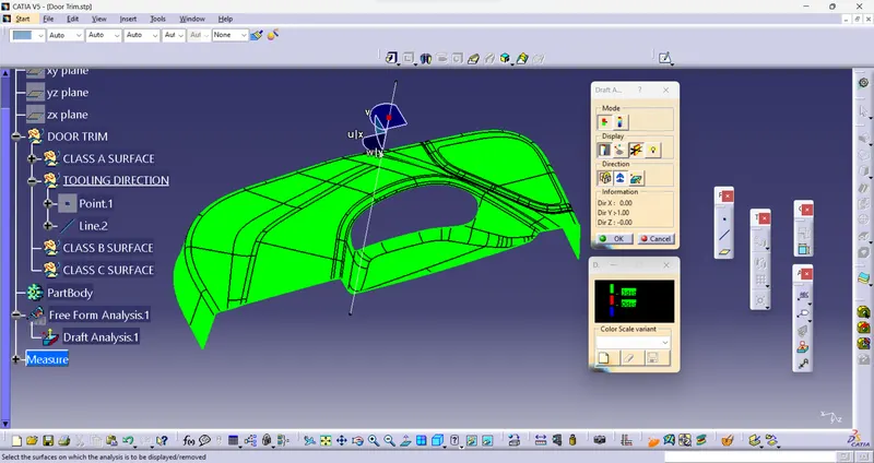
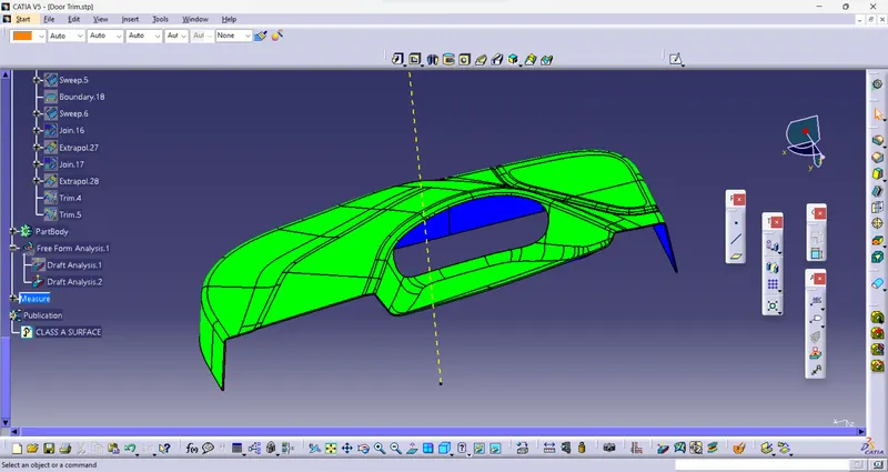
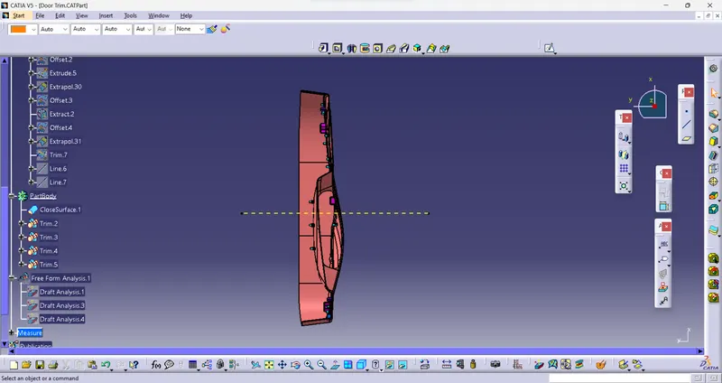
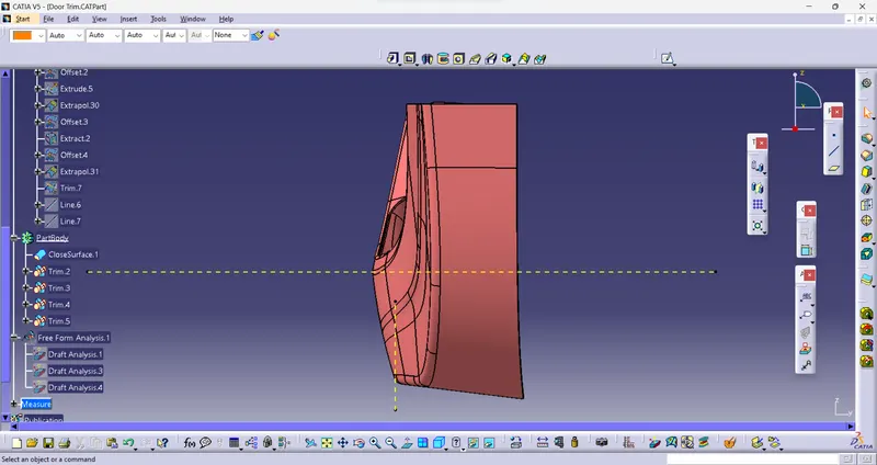
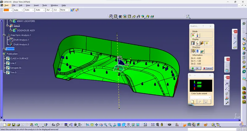
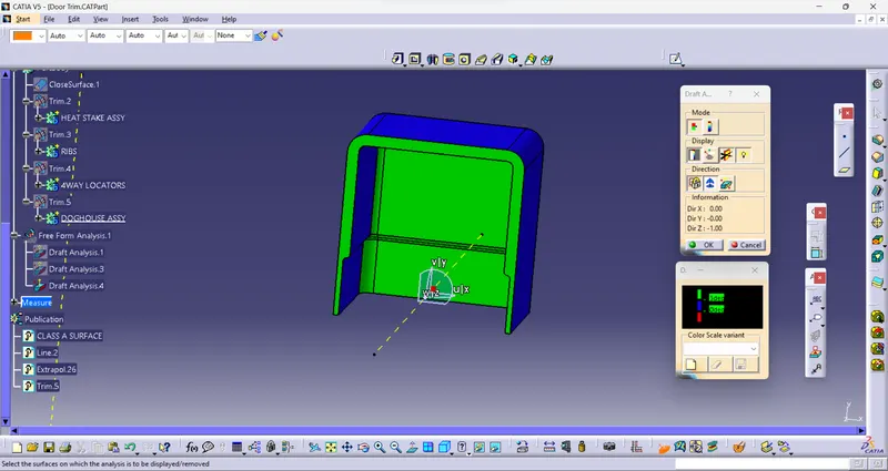
As we know minimum draft angle for the faces of the plastic component should be 3 degrees. So the value of 2.9 degrees (considering tolerance) is provided in the Draft analysis color mode window Inside the color scale, the GREEN bar shows the draft angle of 2.9 or above 2.9 degrees. The blue bar shows below 2.9 degrees draft angle the other limit being and the RED bar shows the negative draft angle. As shown in the image below all the top faces and side faces of the component are green, while the bottom faces are red. The line of demarcation between the green and red faces is the parting line which divides the core and cavity halves. The solid model has cleared the draft analysis successfully as shown in the image below.
CREATING THE RIB
Ribs are thin wall protrusions that extend perpendicularly from a wall or plane. They are usually found in clusters offering support to a plane that would have otherwise been too thick, but can also be stand-alone support for a single wall. They are commonly used to provide additional support and strength to a part. Thickness and location are essential to rib design.
First, the base surface where the rib has to be created is extracted using the Extract command.
Next, the profile is extruded, to find the height, h=Wall thickness * 5
=2.5*5
= 12.5 mm
Therefore, the height is 12.5 mm
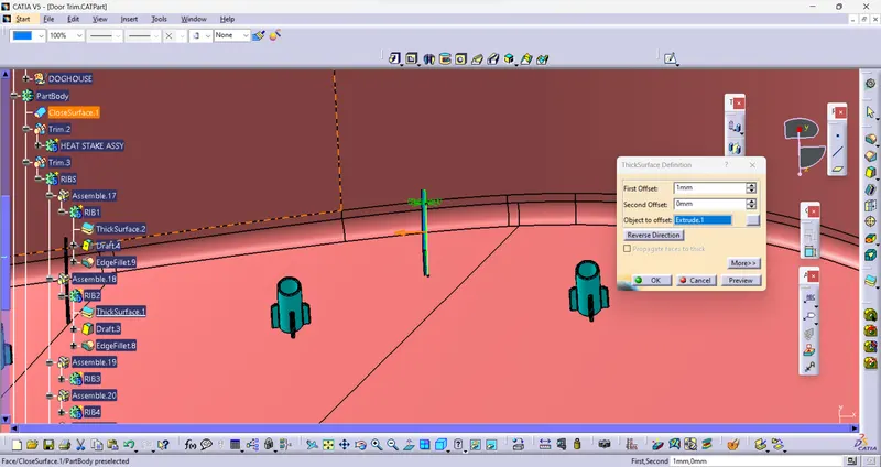
The extruded surface is thickened,
Thickness=0.4*t
=0.4 2.5
=1mm
Therefore, the thickness of the rib is 1 mm
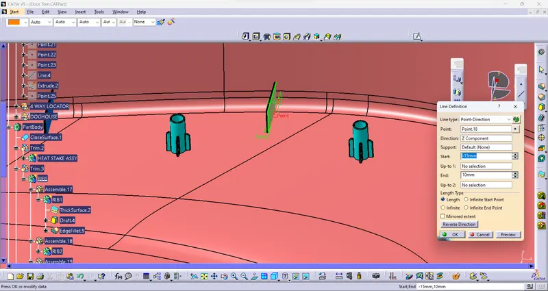
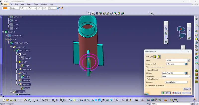
The draft is applied to the sides of the ribs. As per the design rule, the ideal draft angle is 0.5 deg
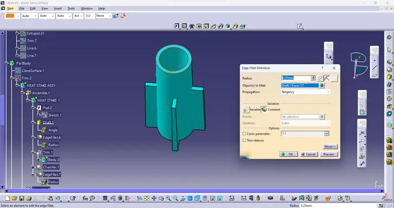
Then fillet is applied to the faces of the rib. As per the design rule, the fillet can be 0.25 mm.
CREATING HEAT STAKE
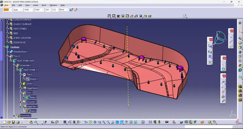
The locators restrict all the other degrees of freedom except the translation along the direction of tooling axis Le along y-axis. For restricting that degree of freedom we will be using the heat stakes.
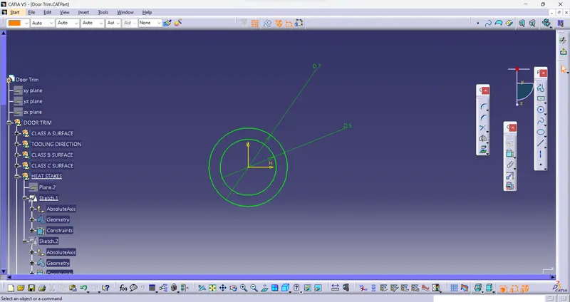
In heat staking, we use local heating and cooling to raise the temperature of plastic components and allow plastic reforming to be carried out.
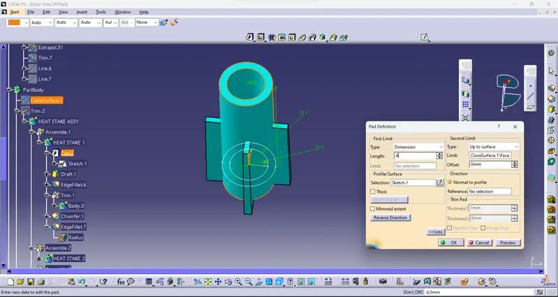
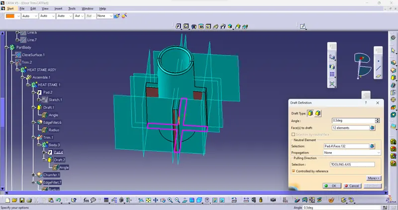
The draft is applied to the sides of the ribs. As per the design rule, the ideal draft angle is 0.5 deg
Then fillet is applied to the faces of the rib. As per the design rule, the fillet can be 0.25 mm.
These heat stakes will enter the mating component and using a heat staking machine these heat stakes are melted and cooled. When cooled this will get hardened and the two components will stick together. Thus, all degrees of freedom are arrested
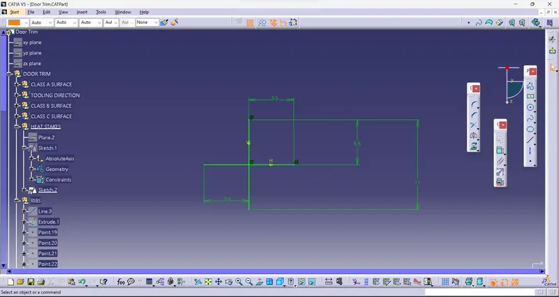
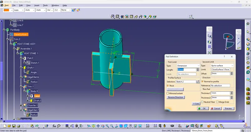
Then, the ribs are created by following the rib design rules.
The draft is applied to the sides of the ribs. As per the design rule, the ideal draft angle is 0.5 deg
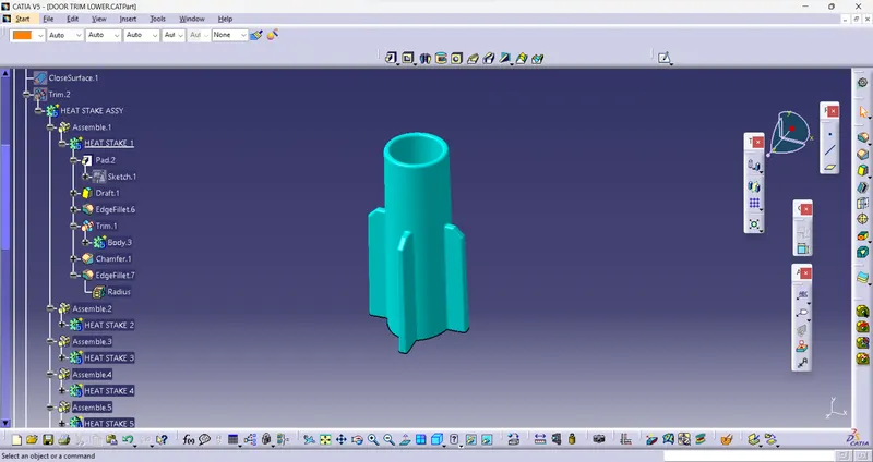
Hence, the ribs are created for the screw HEAT STAKES
CREATING THE 4 WAY LOCATORS
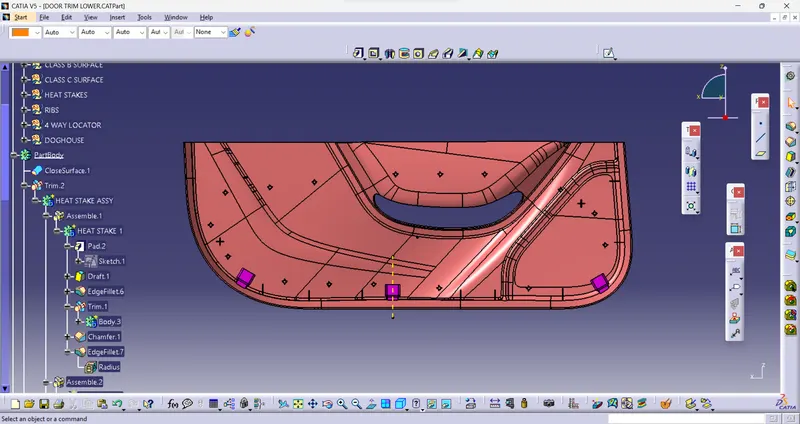
Locators are 4-way locators. The locators will follow the rib design guidelines and will be given a minimum draft of 0.5 degrees and a minimum fillet of 0.2mm and an entry chamfer of 3mm. This entry chamfer is given so that the locators can mate with the other part easily.
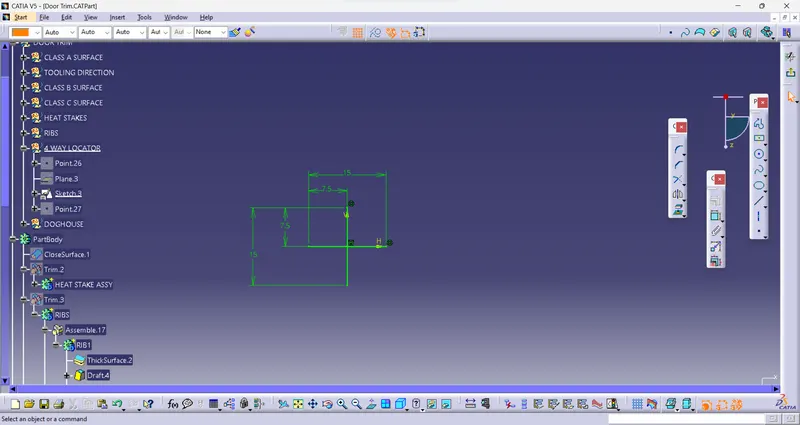
The draft is applied to the sides of the ribs. As per the design rule, the ideal draft angle is 0.5 deg
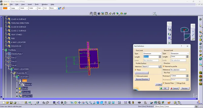
CREATING THE DOGHOUSE
The dog house is an engineering feature used in the plastic trim design. Dog houses are used as a supporting feature. Sometimes other engineering features like snaps; locators, etc. are mounded on them to increase their strength.
The doghouse is created by following the design rules.
The nominal wall thickness guide range is from 0.75 mm to 3 mm for reinforced materials and 0.5 mm to 5 mm for unreinforced materials.
Related Courses
WALL THICKNESS (W) = 0.70 (NOMINAL THICKNESS OF PLASTIC MATERIAL)
This process is usually done by Thicken surface command.
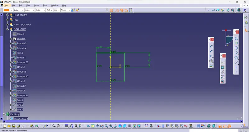
The fillets and the draft are given as per the design rules.
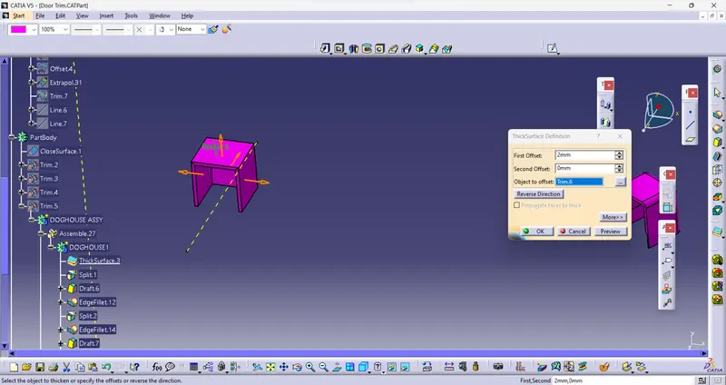
An important thing while designing a doghouse is to maintain 40% less thickness than the wall thickness (T) at the area of the intersection to avoid sink marks. So, a C shape is formed at the intersection.
This can be made using the split command to remove the solid at the intersection
Draft Analysis
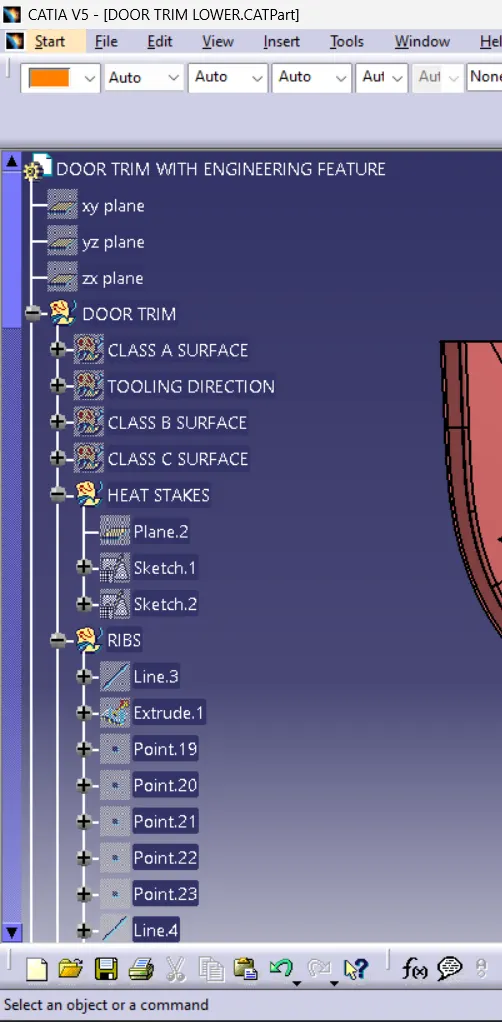
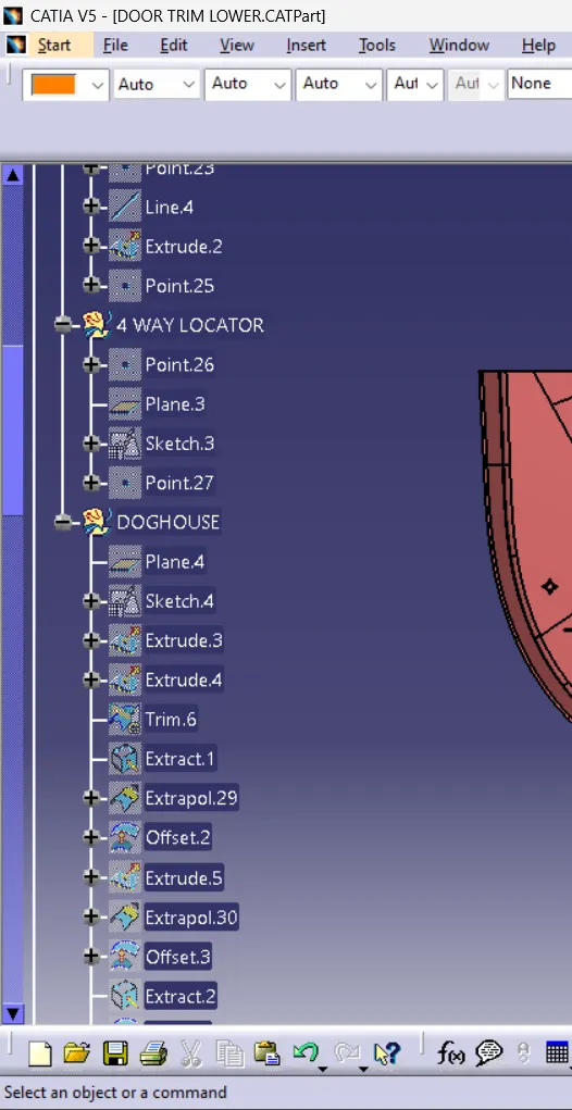
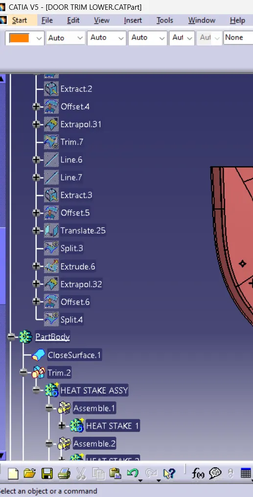
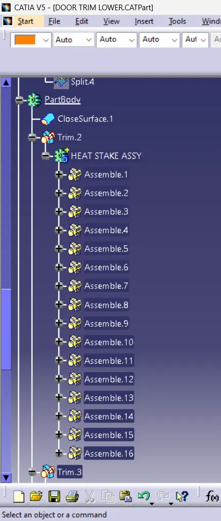
TREE STRCTURE