Week 9 - Project 1 - Door Trim Lower with Engineering Features
TOOLING AXIS:
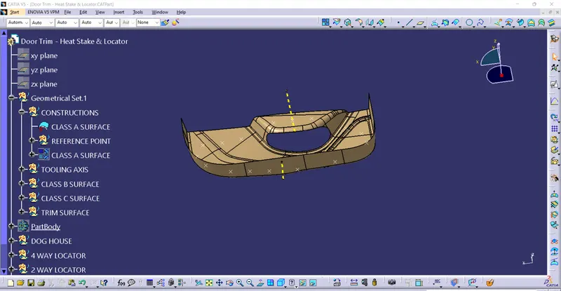
*The Direction in which the mold or core and cavity opens is the tooling axis.
1) connectivity of class A surface:
cheking the connectivity of the surface,this can be done by creating boundariesor by simply using such as that any opening can be easily visualized.
2) Analysis visually for the best possiable tooling axis.
A Dummy tooling axis will be directly created using point dirction command.
checking possiabilities (clearance) in all the direction of axis and find what are the problem creation parts of the component or model.
The clearanace checking along all the axis direction will be done by creating an intersection along an axis on a plan with the model and constructing two lines contact with the walls,the line bisecting the two lines and passing through the point will be the tooling axis.
3) created the side core axis for dog house
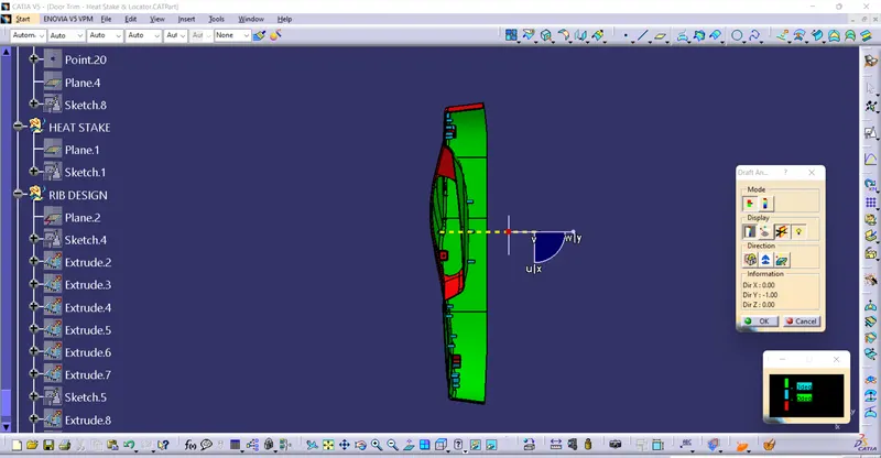
DRAFT ANALYSIS:
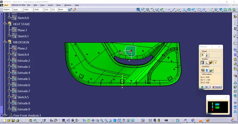
* Enter the part diagram of the catia.
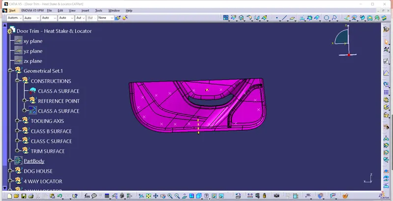
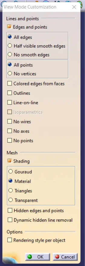
* customize view parameter go to to the material mode.
* go for the draft analysis
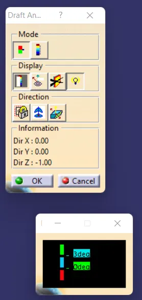
*drag axis bar to the tooling direction of part.
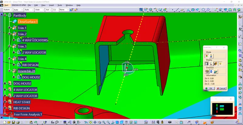
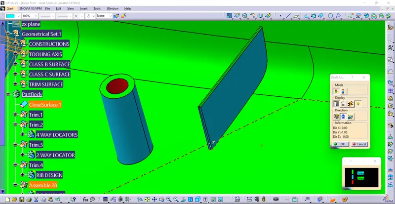
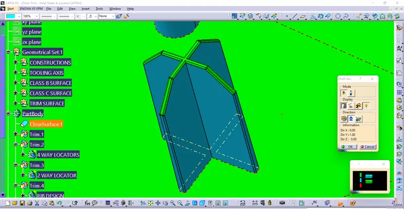
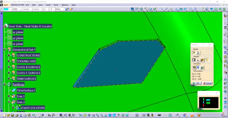
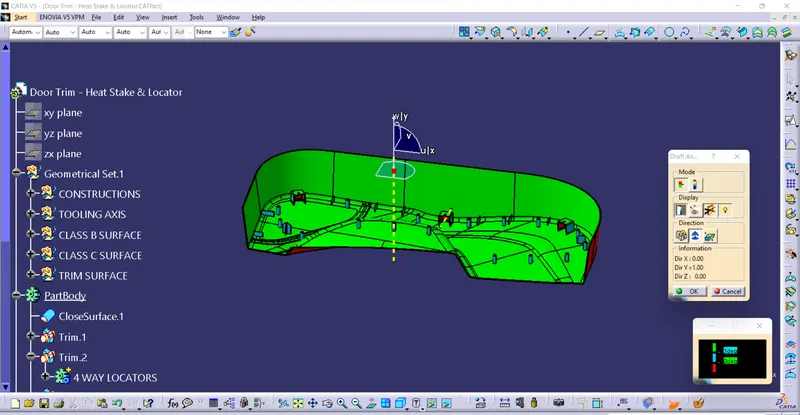
when the drafting analaysis was 3 degree
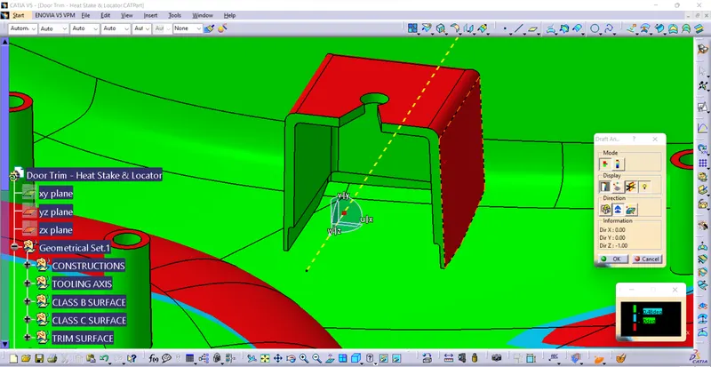
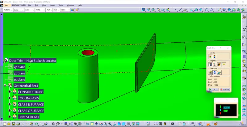
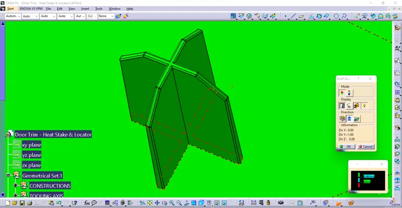
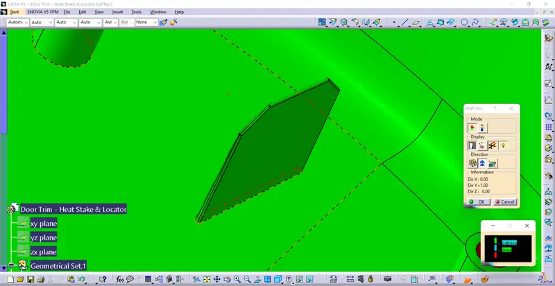
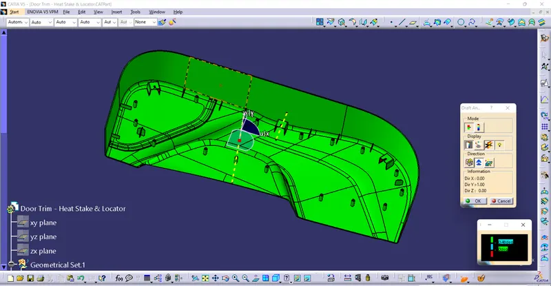
when the drafting analaysis 0.48 degree.
* check for draft and make parting line as per analysis.
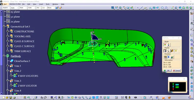
TREE DIAGRAM:
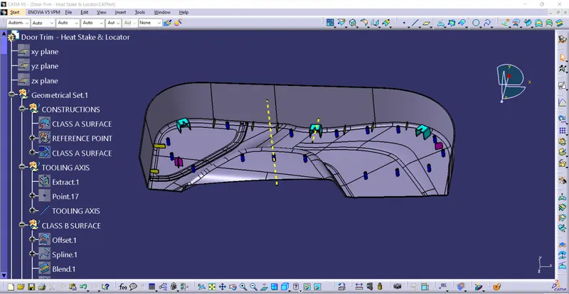
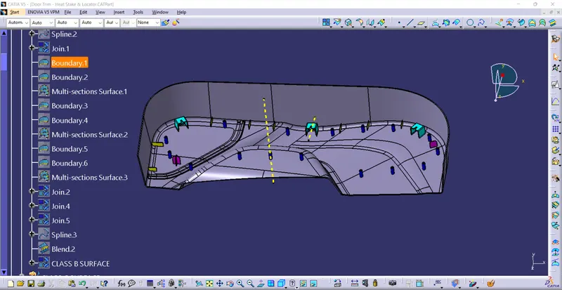
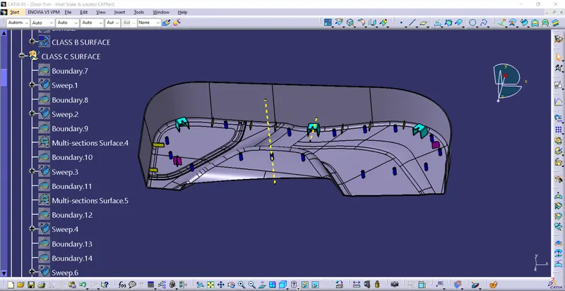
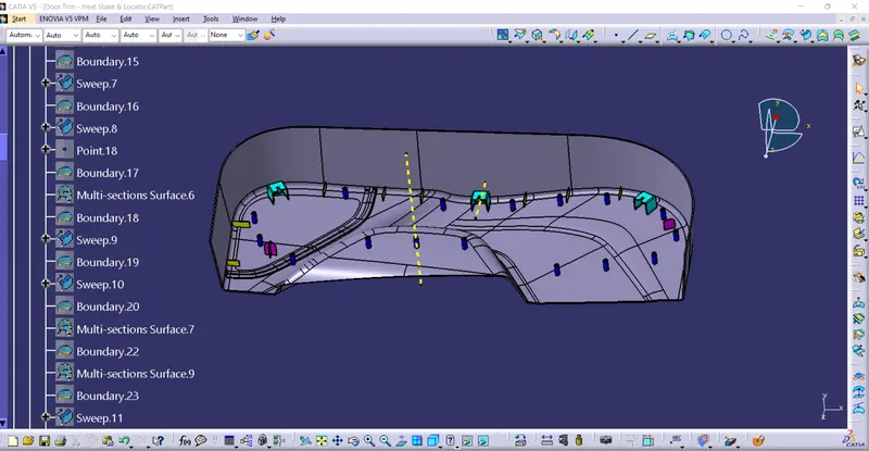
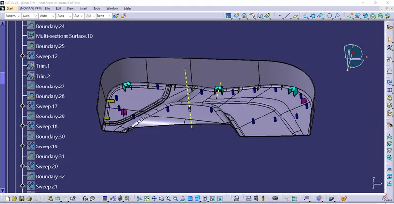
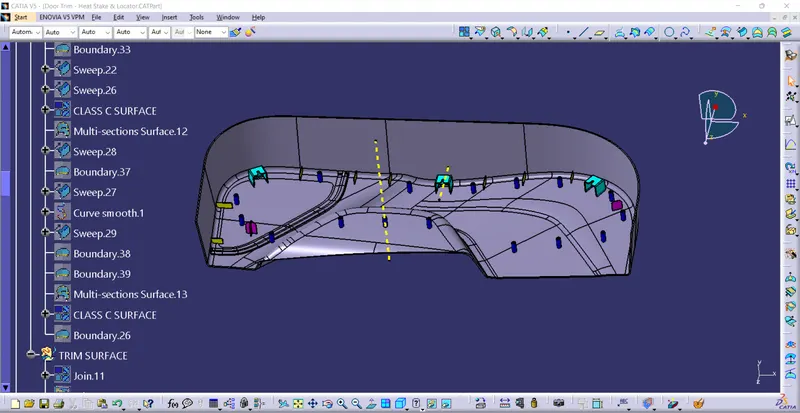
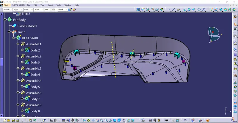
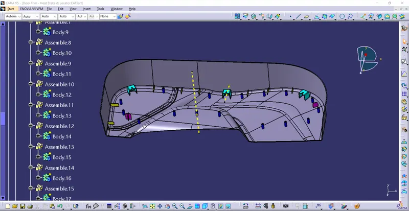
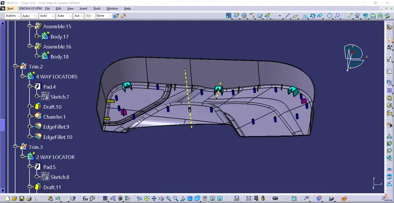
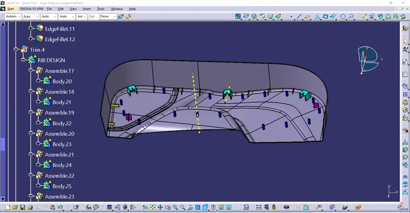
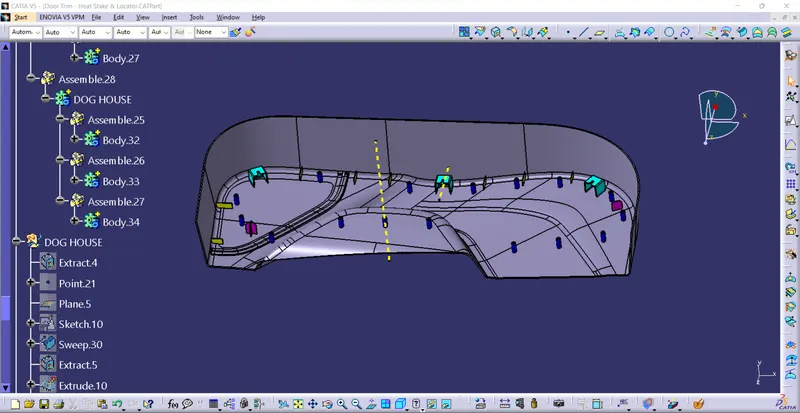
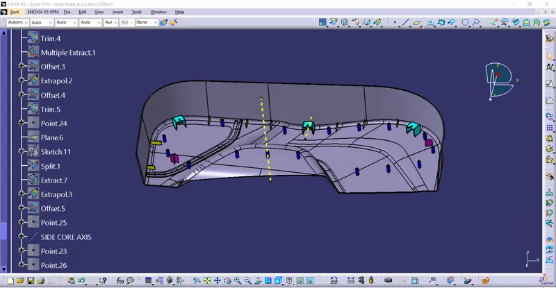
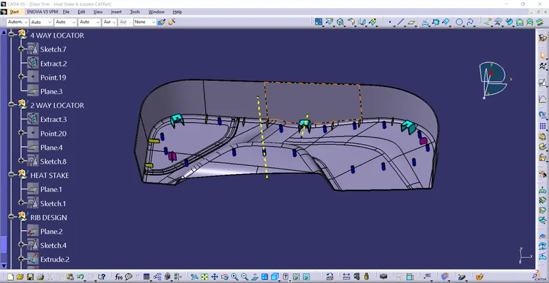
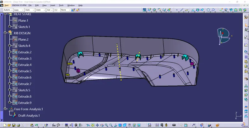
EXPLANATION:
1)when creating the door trim heat stake.
2) Frist we open the door trim heat stake and we draft the class A surface.
3) And we create the tooling axis and we can offset the class a surface and we create a class B surface.
4) And we create a class C surface and with the help of swep and some other tools.
5) we can joint the C surface and A surface and we can check the intersection of join the class c surface and class A surface and class B surface.
6) And we can trime the bothe the join of class c and A surface and B surface.
7) create a dog house use of outer radius 2mmand inner radius 1 mm and 0.5 mm radius and 0.5 draft angle of dog house.
8) create a ribs 0.25 radius and height 5*2.5=12.5mm and draft angle 0.5. 8 ribs are created
9) create the 4 way locator and 2 way locator draft angle 0.5 and chamfer 5mm.
10)create the heat stakes of the draft angle 0.5 16 heat stake are created .
3D VIEWS:
ISOMETRIC VIEW :
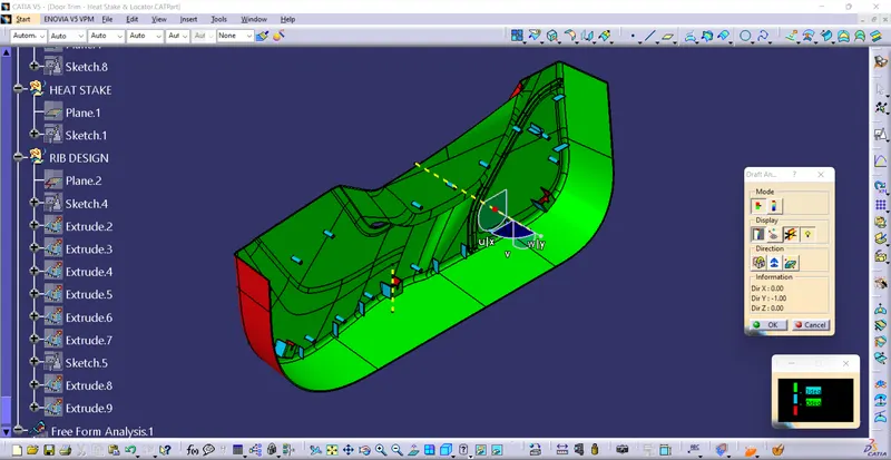
LEFT VIEW:
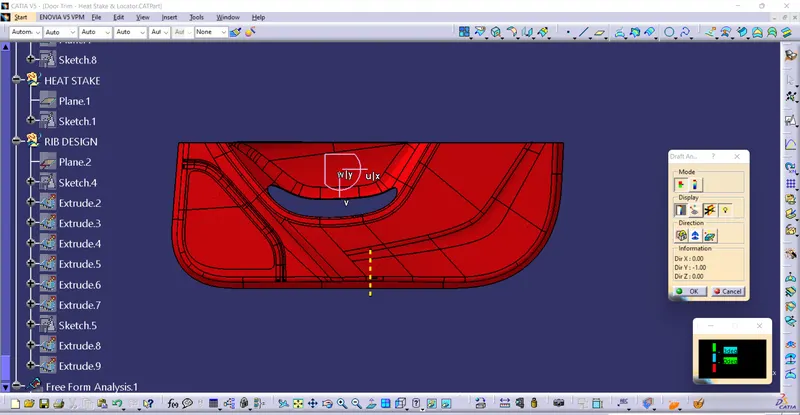
RIGHT VIEW:
TOP VIEW: