Week 9 - Project 1 - Door Trim Lower with Engineering Features
AIM:
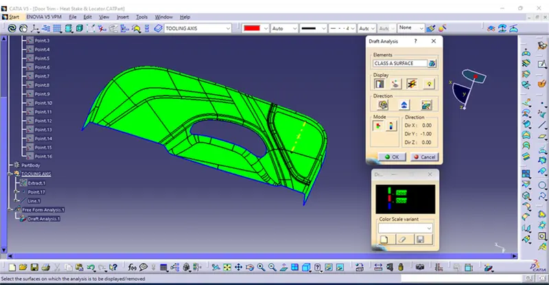
Create the Door Trim Lower Plastic component through the given Class-A surface. To begin with, the tooling axis for the given Class-A Surface should be created meeting the requirements of the draft angle and at the end perform the Draft analysis on the model.
Create the Heat Stakes and the locators considering the design rules mentioned in the video for the door applique.
CLASS A SURFACE:
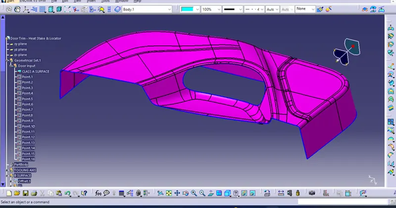
Upload the given CATpart file. the class a surface is-
TOOLING AXIS CREATION:
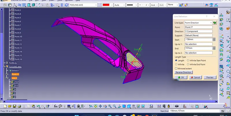
Generally tooling axis is created using bisecting line method. But in the components where it has a number plat area, then the tooling axis is considered as a line normal to the base surface of bin. Same is done with this component. A line normal to base surface is created and considered as tooling axis.
Class A draft analysis
Class B Surface Creation-
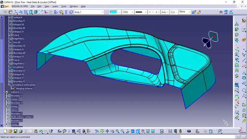
To create Class B Surface first Extract The class A surface using 'Multiple Extract' command. Then Offset The extracted surface with proper distance and direction (Downward), where distance is nothing but the thickness value of the part. In this case some part of the surface might not be offered. For those areas we have to use 'Multi-Section Surface' & 'blend' command with proper edge and guide curve and have to create those areas. Sometimes it might need to extract that particular area of surface and then follow the same process to create the surface.
Class C Surface Creation-
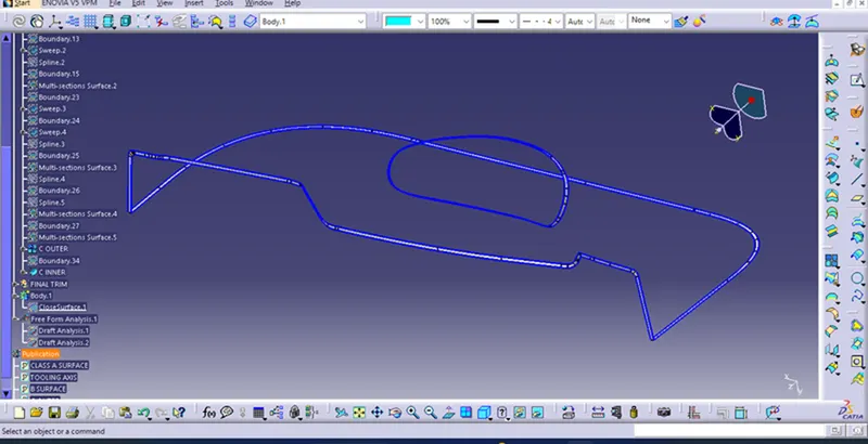
What Class C Surface does, is join the both Class A & Class B Surface. So to create the Class C Surface, first create boundaries using 'Boundary' command with using edges of Class A Surface. And then create a surface using 'Sweep' command at a angle of 90 deg. with class A Surface using those boundary. It might create error when try to make sweep with one single boundary of Class A Surface edge, so for that case we have to take several boundaries according to fusibility. And then trim those sweep surfaces with class B surface to make sure there is no excess surface beyond class B surface. So my final Class C Surface was
Final Closed Surface-
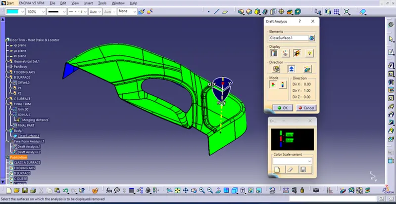
After creating all surfaces, join them together using 'Join' command. And my result is-
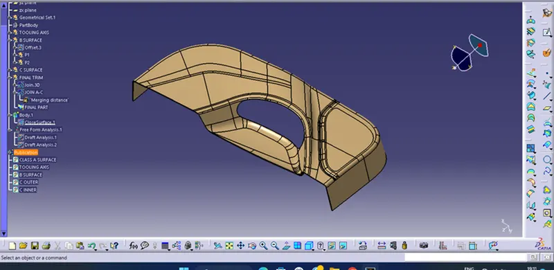
Final closed part draft analysis
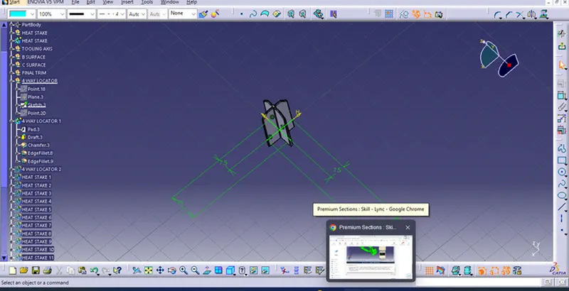
Four way locator design:
- To create the locators, I created a sketch of the body. After creating the sketch, I padded it 19mm in height and thicken it to 1.3mm and I drafted it with 0.5deg in the direction of the tooling axis.
- I gave 3mm of chamfer with 45deg of inclination and after I gave a fillet of 0.25mm radius. Iso-Constrained Sketches
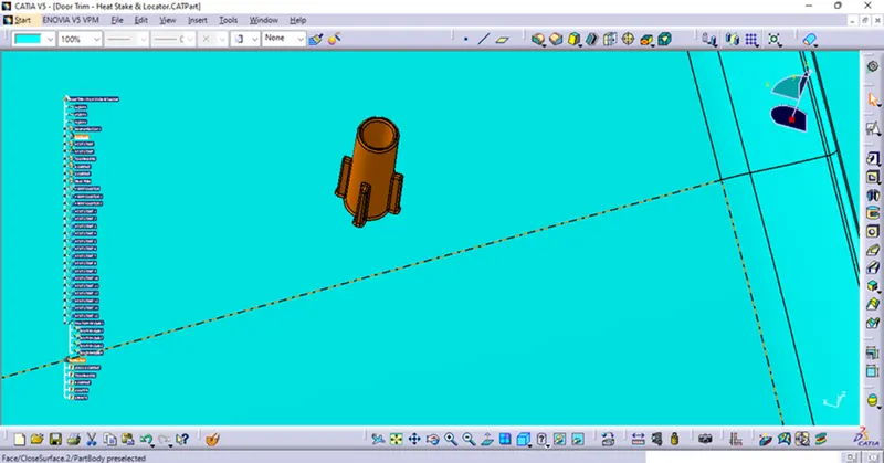
Heat stake design
- To create the heat stakes, I sketch on the surface. After the creation of the sketch, I padded it to 18mm height and I gave a draft angle of 0.5deg on both sides (inside and outside) and then I gave a fillet with a 0.25mm radius. After creating the heat stake, I created the ribs for supporting purposes. To create the ribs, I draw a sketch and padded it to 6mm in height and 1.3mm in thickness.
- After padding the ribs, I drafted 0.5deg in the tooling axis direction and filleted it with a 0.25mm radius. Iso- Constrained Sketches.
- Now I translated the heat stakes by copy-pasting them in the part body according to the requirement.
final component:
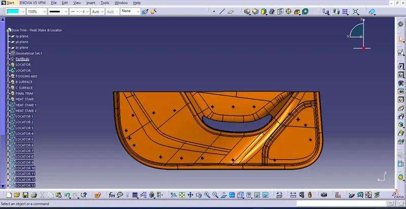
final component draft analysis:
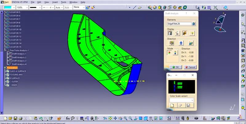
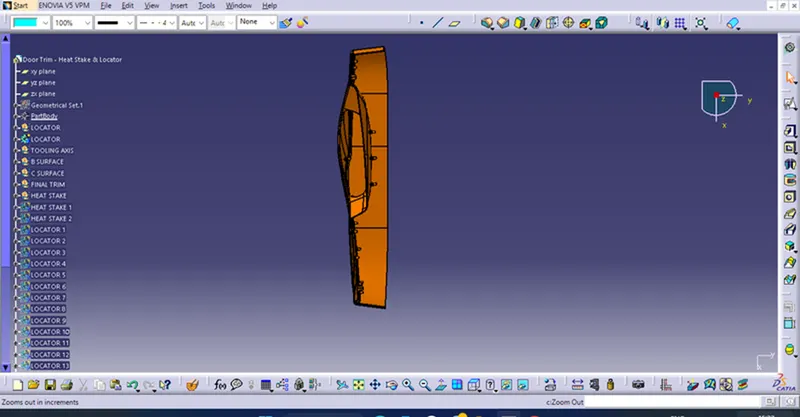
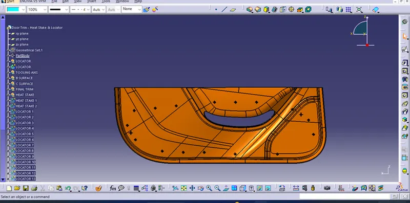
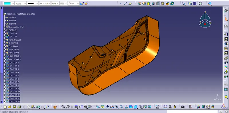
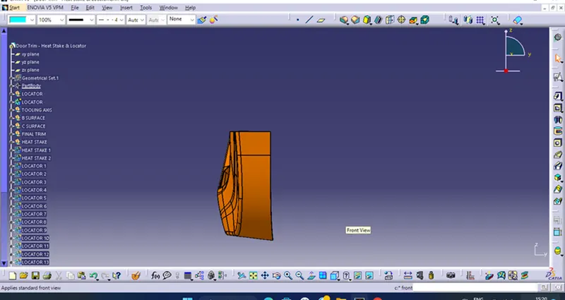
- Screenshots of the completed design in various orientations (Isometric, Front, Side, and Top View)
Isometric view
Fornt view
TOP VIEW