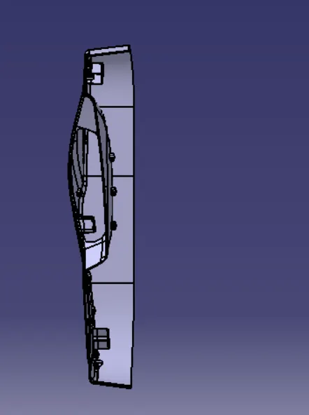
Week 9 - Project 1 - Door Trim Lower with Engineering Features
Creation of Tooling Axis:
For Creating the tooling axis, we create a straight line from the selected point on the surface in the Y direction.
BISECTING METHOD
This method is used for the generation of the tooling axis for that purpose first we need to decide the direction of molding and then we create one dummy tooling axis for the reference to the purpose.
In this method, we select the surfaces which can create problems and take intersections in the x and y-direction. By using these curves we draw two lines and then draw a bisecting line from these two lines in the x-direction and y-direction.
If it is done in x-direction then it is called a tooling axis clearing x-direction and if in y then tooling axis clearing y-direction.
After completing this we need to draw a final line bisecting this two tooling axis in the X and Y directions to get our final output.
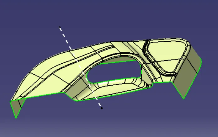
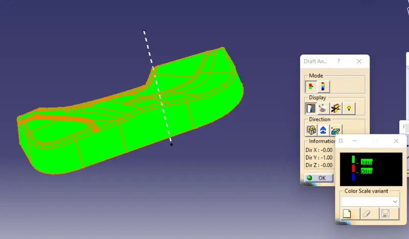
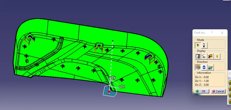
Checking the tooling axis by draft analysis.
The draft analysis is done to determine if the designed part is tool able or not. Here the tooling axis is 3°.
By using the compass option, drag and place it on the tooling axis. Click ok then check the result.
Part Design:
The B surface is created by an offset value of 2.5 mm:
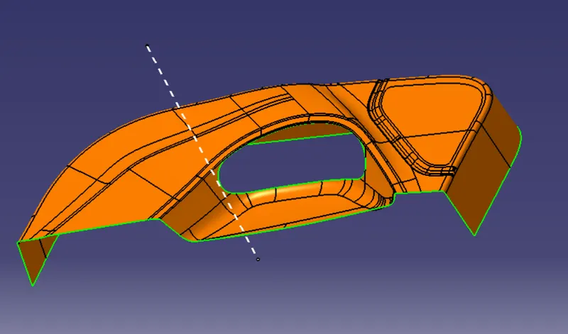
C SURFACE
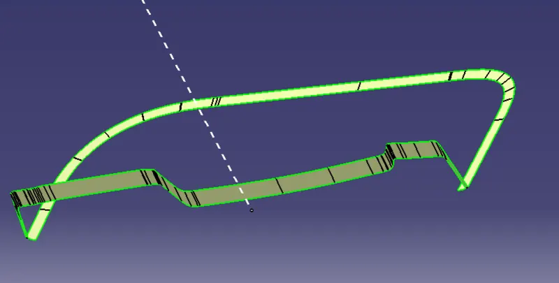
FINAL TRIM
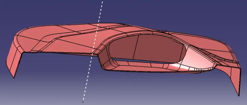
AND USING CLOSE SURFACE
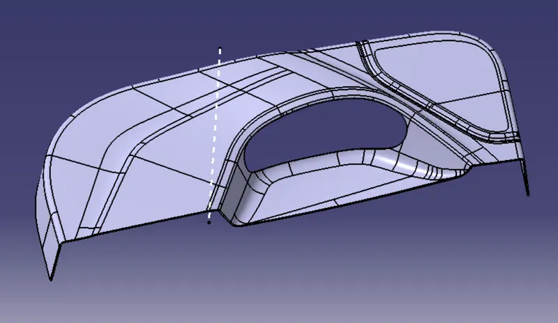
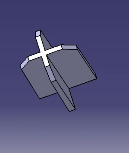
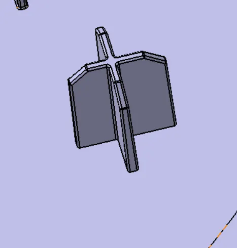
Locators:
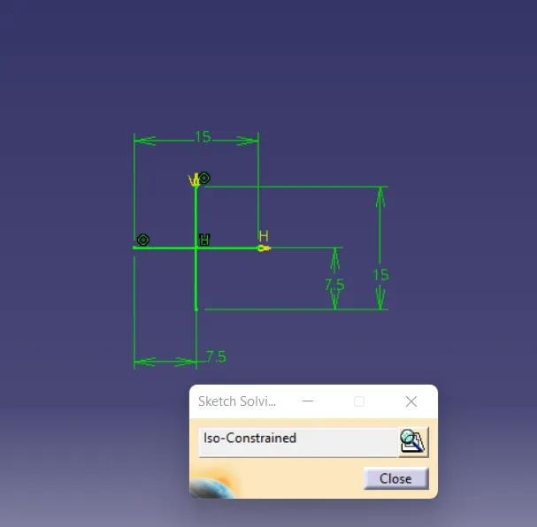
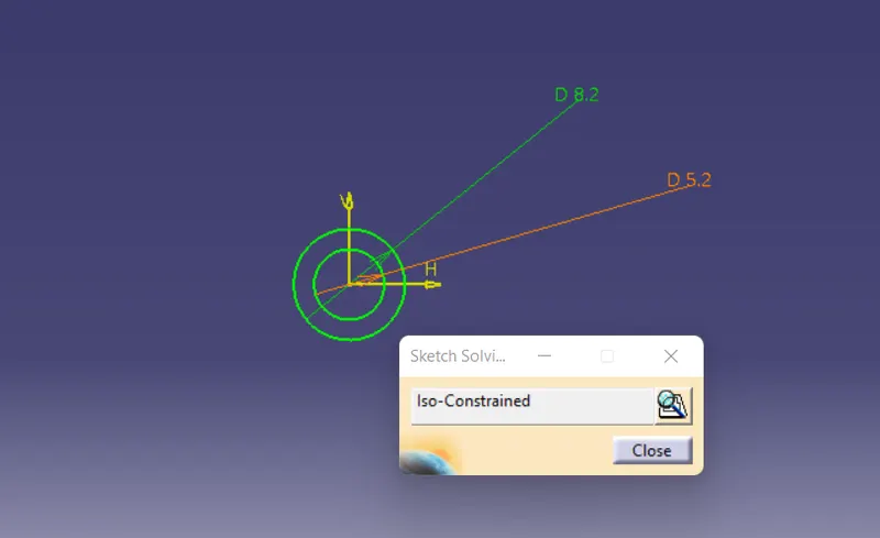
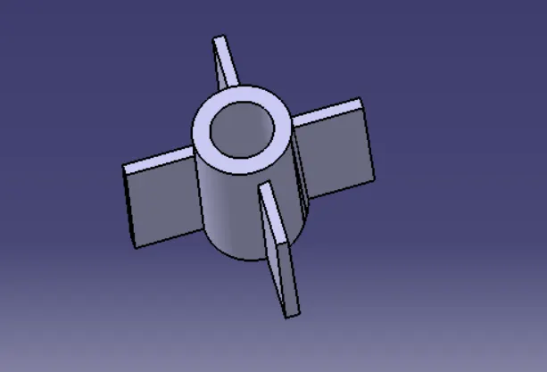
Heat Stakes:
Final Draft Analysis:
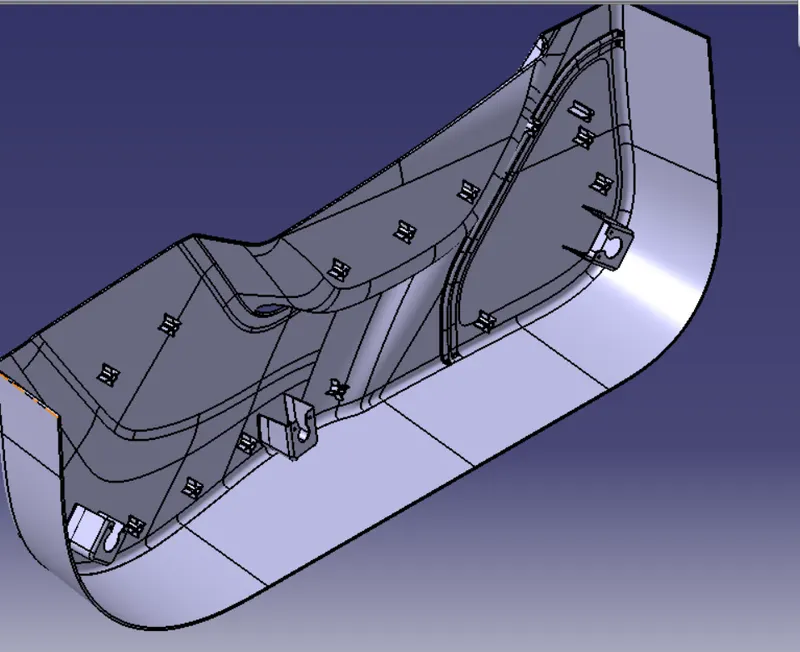
ISOMETRIC VIEW
FRONT VIEW
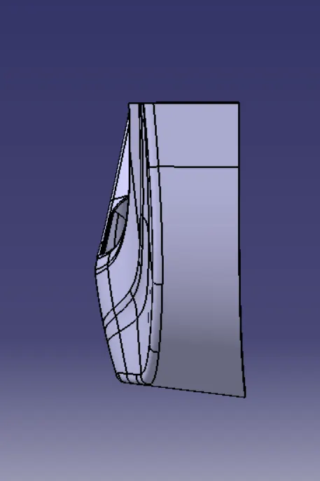
SIDE VIEW

TOP VIEW