Week 9 - Project 1 - Door Trim Lower with Engineering Features
Project 1 - Door Trim Lower with Engineering Features
AIM:
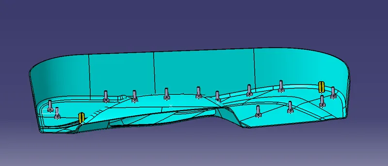
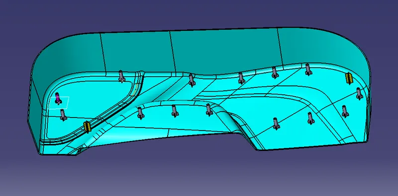
To create Plastic design and attach the Engineering features Heat stakes and locator , generate the Draft Analysis for the given Door Applique Class A model.
Steps followed.
The Class A surface is charged for the connectivity of the surface and ensures it is completely joint and there will be no gap between the surfaces.
If it is not joined together, make it with a minimum tolerance of 0.001 or 0.003 and check for the connectivity of the surface.
Connectivity of the surface can be done by 2 methods by join method and the boundary method.
Creating the tooling axis, we can create the tooling axis by creating an intersection method by creating a bisecting line
Draft analysis on class A and identify the draft angle then give the nominal value.
Tooling Axis.
The direction in which the mold opens and close is called the tooling axis direction.
Check the connectivity of the surface and ensure there will be no gap between the surfaces and then define the tooling axis.
While creating a tooling axis, Please ensure to give the tooling axis on a flat surface or the surface which have a hole in it.
Create a point on the middle of the base surface by using a point on the surface comment. Then create an intersection for the surface and extract the reference line which will be helpful for creating the dummy tooling axis using the Intersecting method by creating a bisecting line.
Use the line command and draw the lines which is aligned with the extracted line and extended it to the required length.
Draft Analysis.
The draft allows for the component to release from the mold. Most parts or applications require a minimum of 0.5 to one-degree draft angle and a 3-degree draft angle is widely used as per the norm
H changes the material mode to customize mode before moving to the draft analysis.
Insert., analysis, future draft analysis.
Defining the draft direction, select draft analysis from the toolbar and click on the compass symbol and pull the combos from the right top corner of the workbench and place it on the component where want to do the draft analysis. W. Of the compass. And tooling axis. Should be aligned. On the same line.
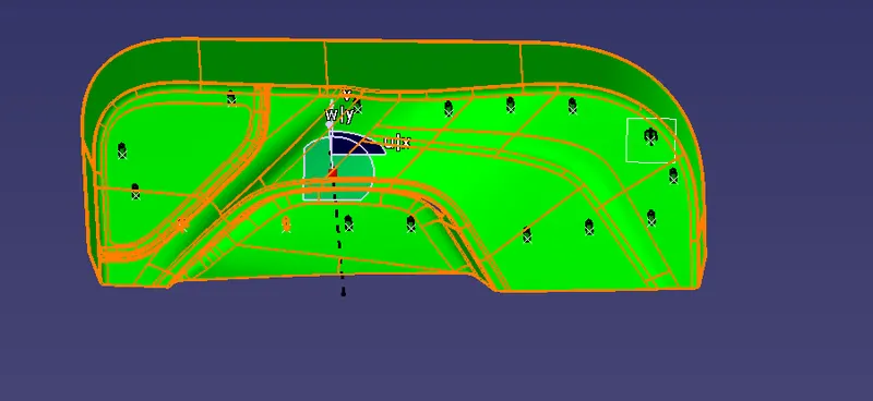
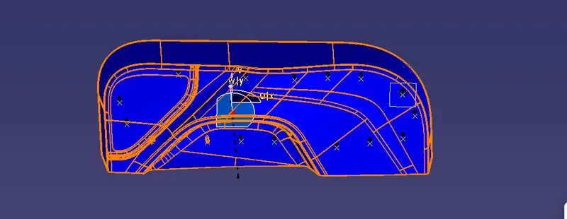
Once the compass is aligned with the tolling axis, click on the lock symbol and drag on the surface. We will get a wrong mark. Then select the point, and a table will appear. It will show the draft value on the table. We can adjust the draft value. Add analysis it for all the edges and surfaces.
By clicking on the surface and using the flipping tool we can assign the flipping direction. The color of the surface changes as per the flipping direction.
Analysis under running point and move the mouse on the surface and it will show the details of the surface degree Direct at each and every point of the surface.
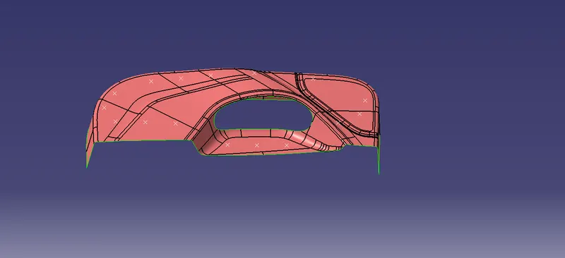
B surface
In the case of class B surface, the surface below is called the core, and the surface above is called the cavity.
Class as an aesthetic surface and Class B is an engineering surface.
Class B surface should be inside the Class A surface.
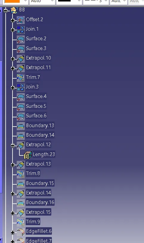
As class A is more complex and has multiple geometries. In this case, we can directly offset the Class A to 3 mm thus we can obtain B surface.
B surface is then checked for the connectivity of the surface, but it will show some patches on B surface. We have to close it by extracting the required boundaries with reference to the surface and spline the uncovered area and close it by using the multi-section surface sweep and extrude method.
All the closed patches is then joined together by using join command and checked for the connectivity of the surface.
C surface.
C surface has been created from the boundary line of the Class A surface. And by extracting the supporting surface, then sweep the boundary line with reference to the extracted surface.
In order to get the sea surface first we have to create a boundary line of Class A surface or by using multiple extrapolated commands and check for its continuity of it.
Create a sweep with reference to the curve and the reference surface with a 90 degree. Angry and give the inside direction. Check for the continuity of the surface. If there is any gap for the extrapolated and trim together, now we will get the Class C surface.
All the C surfaces are then trimmed to be surface. And then joined the trimmed surface. 2 Class A surface by join command. Then check it for connectivity. Of the surface, We will get the final component. Again Check whether the final body Is closed by Using a boundary comment.
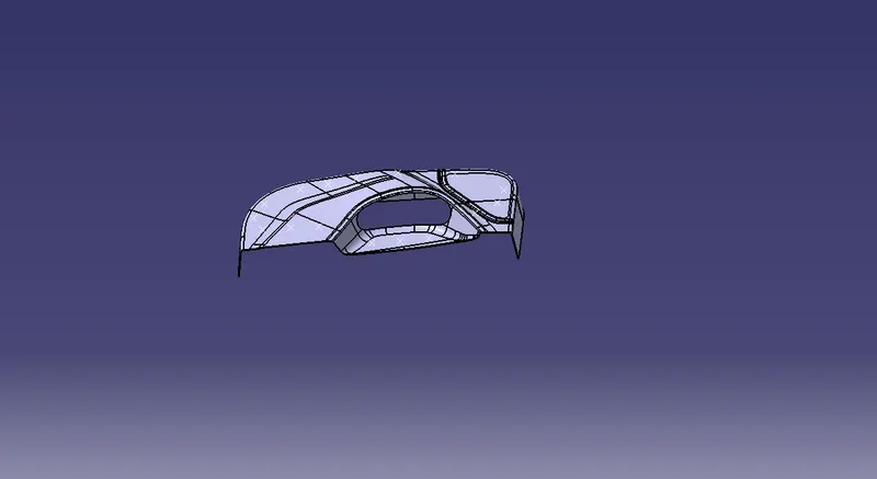
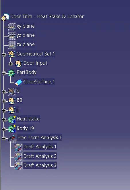
A close solid body can be obtained by using the close surface on Part Workbench by selecting the final trimmed component.
Close body Is created by using the close surface on the part workbench by selecting the final trimmed component and do the draft analysis for the same.
Heat Stake:-
Heat staking also known as thermoplastic staking is the process of joining two dissimilar materials together. In heat staking, we use local heating and cooling to raise the temperature of plastic components and allow plastic reforming to be carried out. This reform can be used in a wide variety of applications.
Applications range from staking plastic bosses for the assembly of car door panels to joining PCBs to plastic housings. Benefits of this technique include; no vibration damage, no particulates, the ability to stake metalized coated applications, and the capability to stake in difficult-to-access or restricted areas.
Advantages of Heat Staking
Consistent, Fast & Economical Alternative to Rivets & Screws.
Joins different materials Eg: Plastic to plastic, plastic to non-plastic or join 2 non-plastics.
Able to handle difficult-to-weld plastics.
Simple mechanism and accurate control.
Industry Applications
Automotive: Reliable solution for interior parts, welding bumpers, tail light assemblies, dashboards & many more parts
Textile: Creates durable seals without the need for glues, clips and yarns in product designs
Appliances: Component welding for large or small household appliances
B SURFACE
SOLID SURFACE
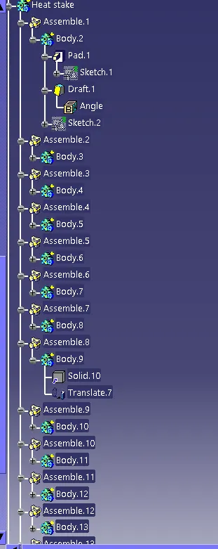
HEAT STAKE AND LOCATORS
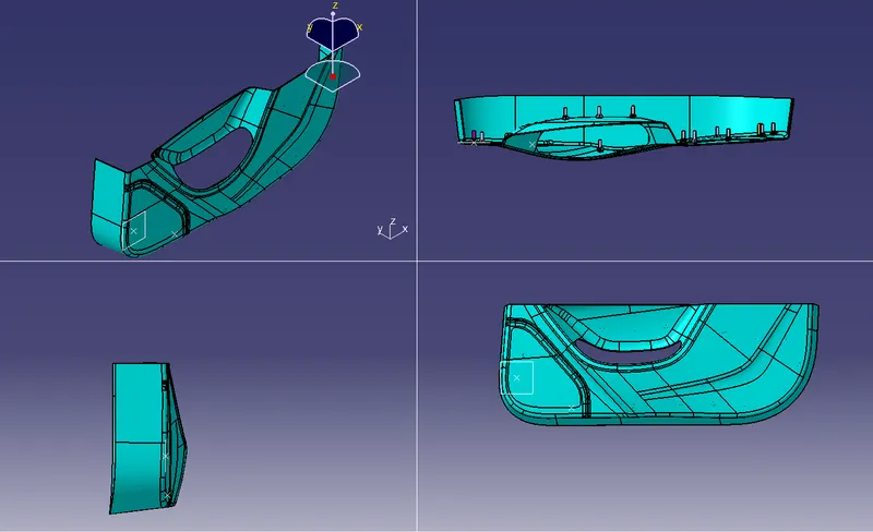
STRUCTURAL TREE
DRAFT ANALYSIS
ALL THE FILES ARE ATTACHED HERE.