Week 9 - Project 1 - Door Trim Lower with Engineering Features
Door Trim Lower with Engineering Features
Aim:
Create the Door Trim Lower Plastic component through the given Class-A surface. To begin with, the tooling axis for the given Class-A Surface should be created meeting the requirements of the draft angle and at the end perform the Draft analysis on the model.
Create the Heat Stakes and the locators considering the design rules mentioned in the video for the door applique.
Condition:
Thickness of the component = 2.5 mm
Draft angle = 3 deg
Sequence:
- Creation of Tooling Axis.
- Creation of Class B and Class C surface.
- Creating a solid part out of surface modelling.
- Draft Analysis of Class A surface and final plastic component.
- 4 Way locator
- Heat stakes
Input:
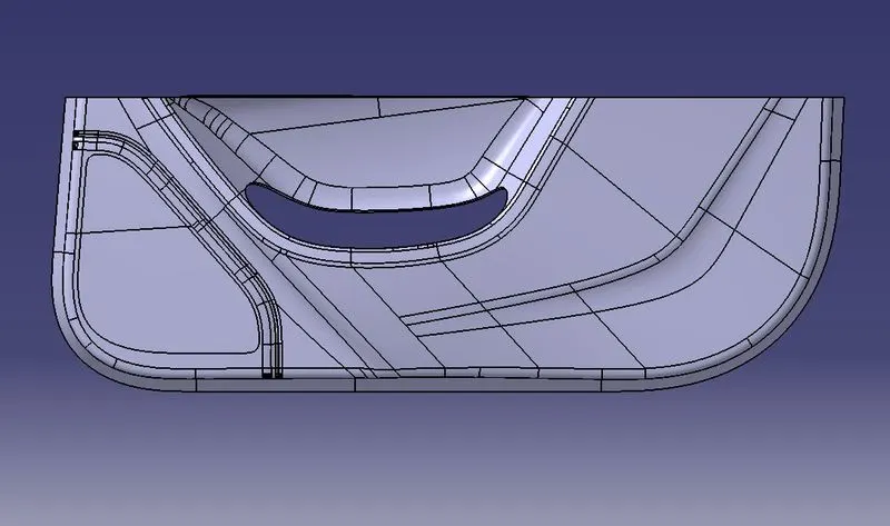
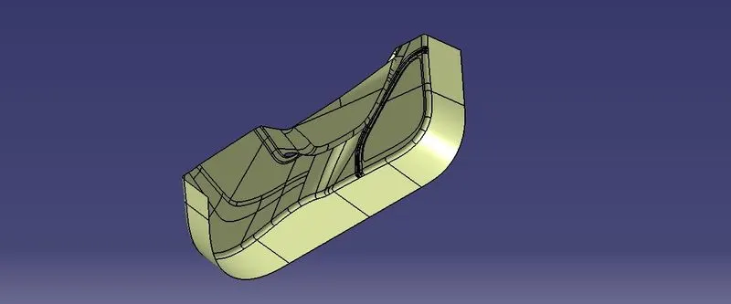
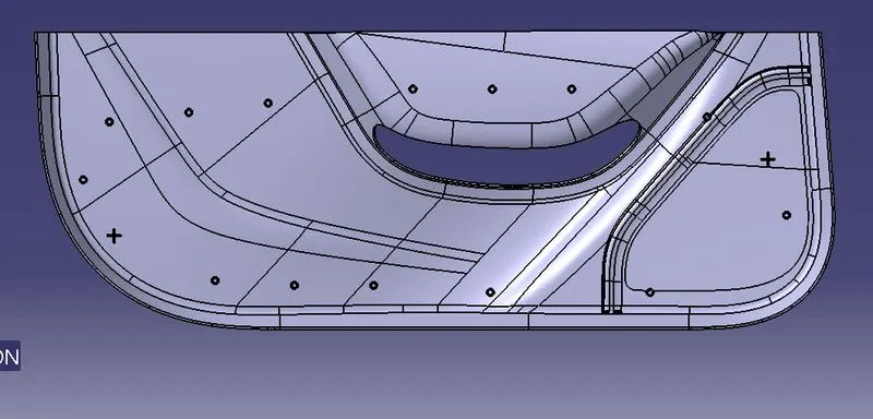
The following surface is given as the input for the component creation.
Input checking:
The given input surface is checked using boundary comment the boundary of the surface is are fully closed or not. If there is any open boundary make sure close it properly.
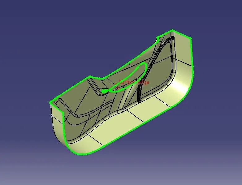
The given input has two boundaries with fully closed condition. So there no problem in creating class B surface.
Creation of Tooling Axis:
Tooling axis the line represents the mold open and close direction at the time of component manufacturing.
If a component has flat surfaces, then the tooling axis identified by visually, otherwise intersection method is used to find the tooling axis of component.
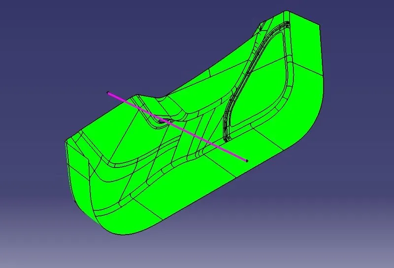
Where the given CLASS A surface walls are not inclined. So, Tooling axis is created with respect to enter or body by visual inspection.
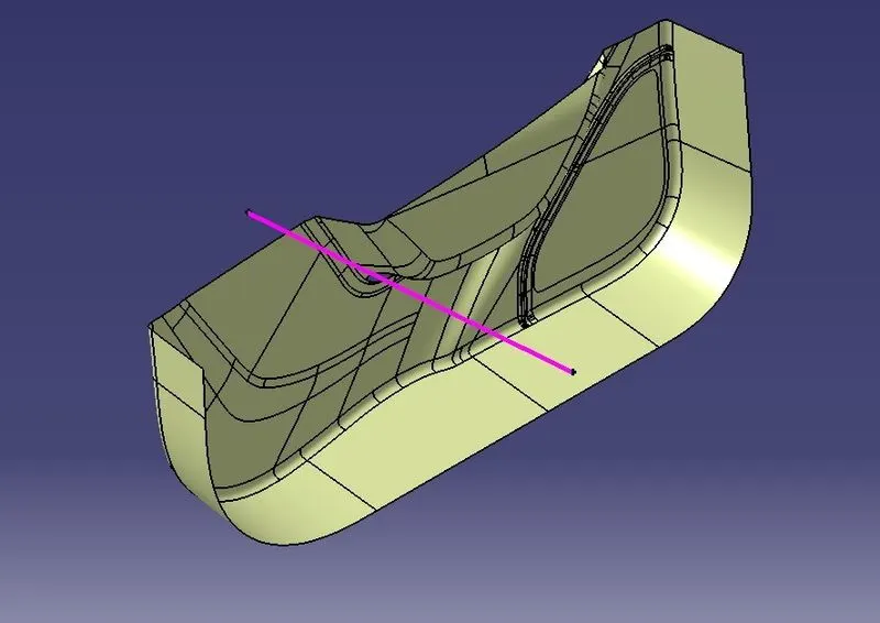
For this component the tooling axis created at the center of body because it has no inclined walls.
The above shown violet Line is our tooling axis.
Draft Analysis CLASS A surface:
Drafting analysis shows that when component ejected from the mold is removed smoothly without creating any damage or scratch on the component.
The minimum draft angle applied on the component is 0.5°. But it need high precision and it increases cost of the mold.
In industry 3° draft angle is used for optimal solution for component ejection.
Here, draft analysis is done with respect to 3° angle.
The draft analysis of class A surface shows that component is clearing the condition for creating component. The green color shows the given input class A surface is good positive draft effect.
Creation of Class B:
The Door trim has many curved surfaces. So, here direct offset used to create the class B surface and done some patching work to complete the class B surface.
After offsetting the class A surface 2.5mm. there is some patching working done one the offset surface. The patching work is done by using the multisection command.
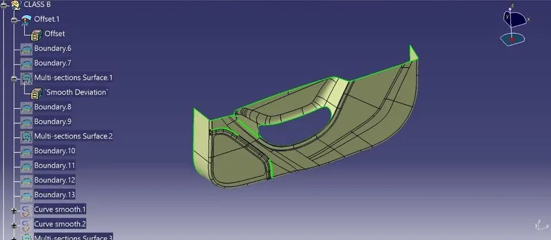
Patching work done places
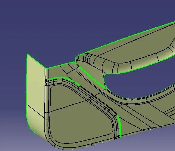
After patching work done all the surfaces are joined together an created into single surface shown like below.
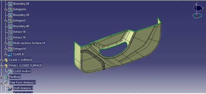
Class C surface:
- For creating class C surface, we have extracted the boundary of Class A using multi-extract and then converted to smooth curve.
- Now this smooth curve is swept along the draft direction with a 90deg perpendicular to CLASS A surface.
- In some places not smooth class C surfaces not formed, In those places multisection command used create the surface.
- Finally, the sweep surface and multisection surfaces are joined into single surface.
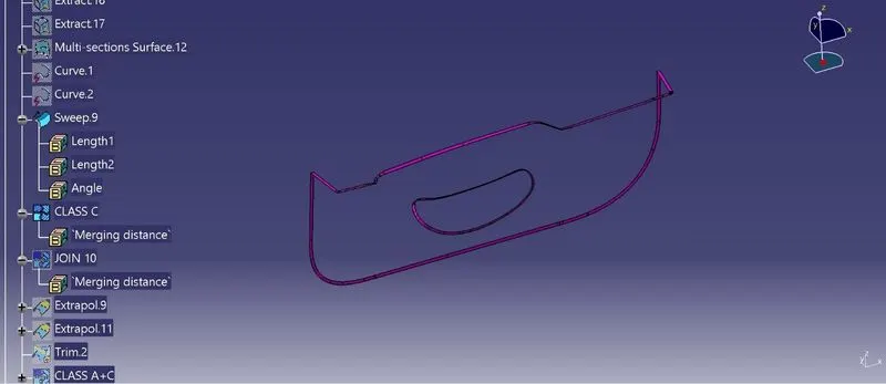
Class A + Class C:
By, joining the class A and class C this surface formed for the final trim operation.
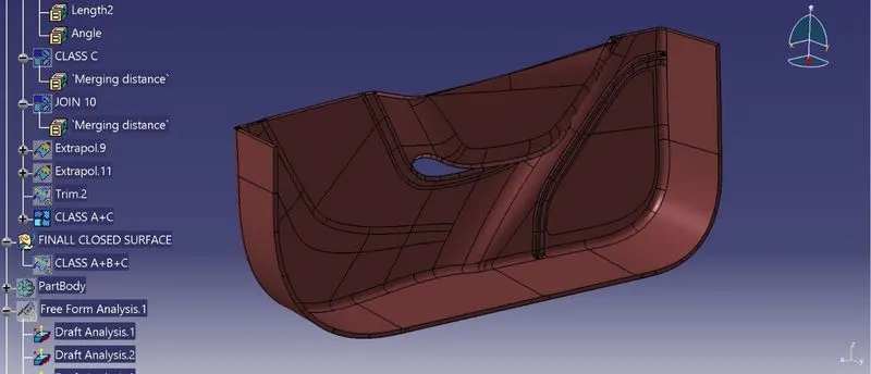
Class A + Class B + Class C:
For this we have trimmed the Class B surface with Class C surface using trim feature. Then the fully closed surface is formed.
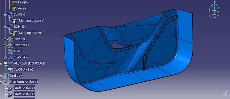
Draft Analysis of body:
Draft analysis needed for every mold component because at the time of mold ejection the component removed without any difficulty or ejecting component should be safe with any crack and scratch on the surfaces with good aesthetics.
Here, Draft analysis done with respect to 3 .
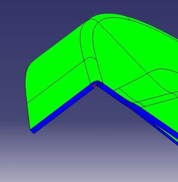
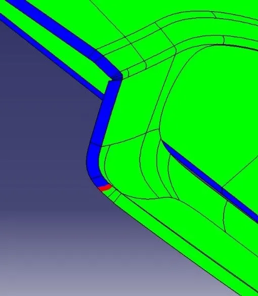
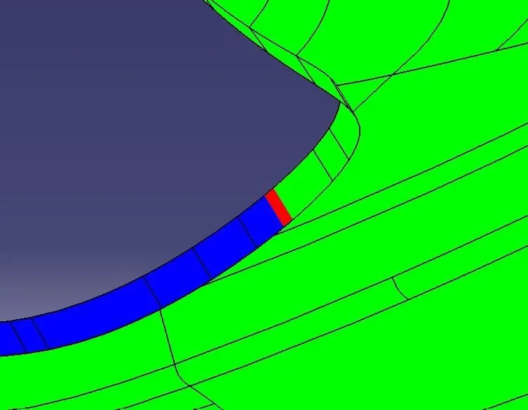
The above shown surfaces are not clearing the draft analysis, so I changed the draft angle to 2.5°.
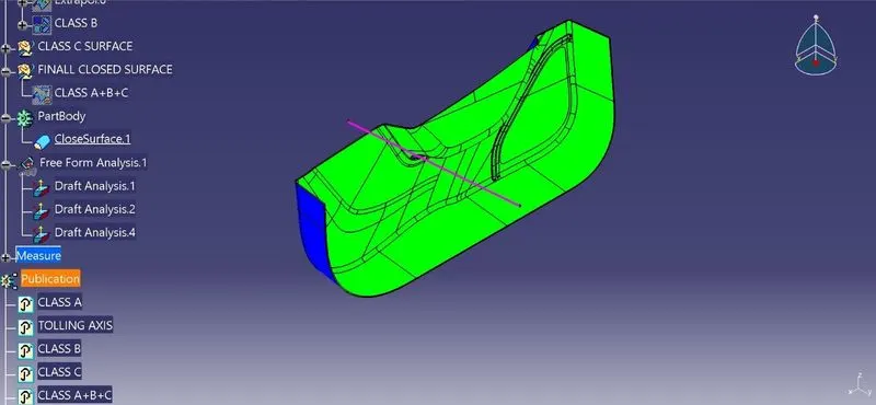
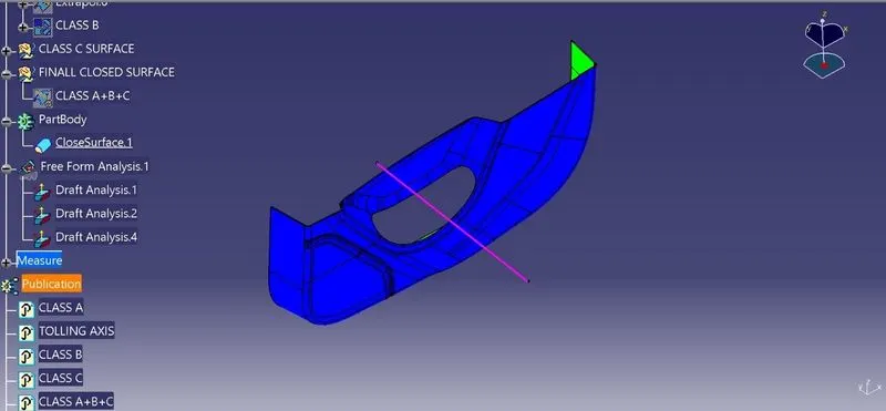
From the above shown draft analysis, the final closed component has positive draft angle in inside and negative draft angle in outside.
It’s shows that the closed surface has no surface is less than 3 deg draft. It means the body clearing the condition of mold ejection.
All the surfaces in body are applicable for mold opening without any wear or tear.
4 Way Locator:
As per the given input point a plane created parallel to zx plane.
In that plane sketch created for locator shown below
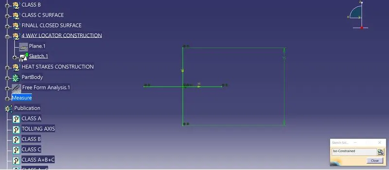
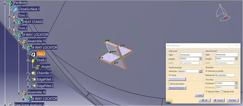
Then pad used to extrude the sketch
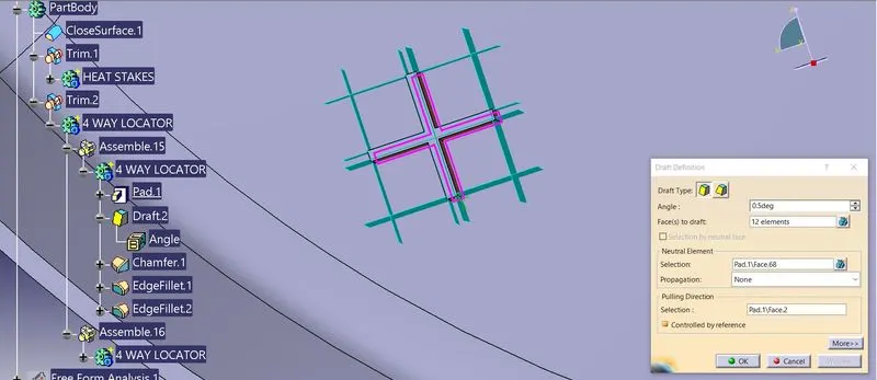
Draft of 0.5° applied on the locator pin
Then required fillet and chamfer applied on the locator.
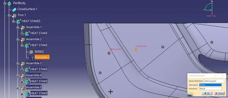
Locator body copied and paste and using translator moved to the required point.
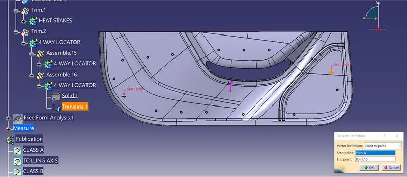
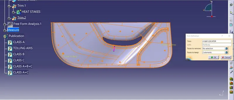
Heat stakes:
As per the given input point a plane created parallel to zx plane.
In that plane sketch created for heat stake shown below
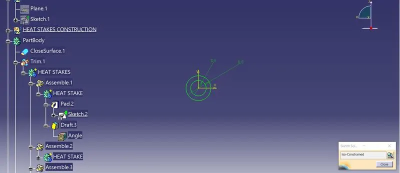
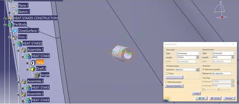
Then pad used to extrude the sketch
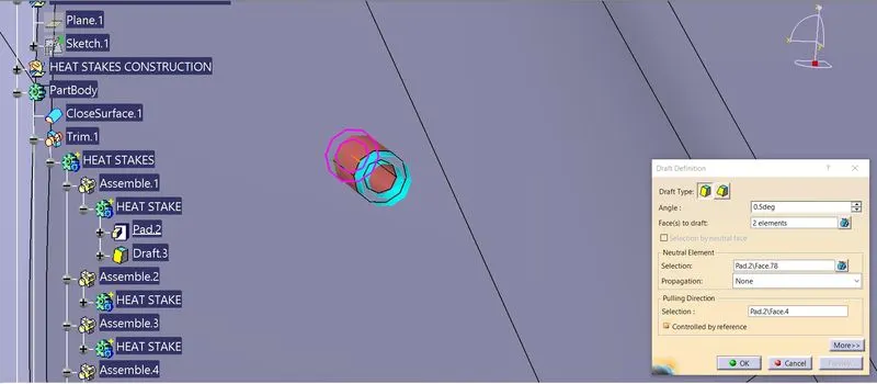
Draft of 0.5° applied on the heat stake
Heat stake body copied and paste and using translator moved to all the required point.
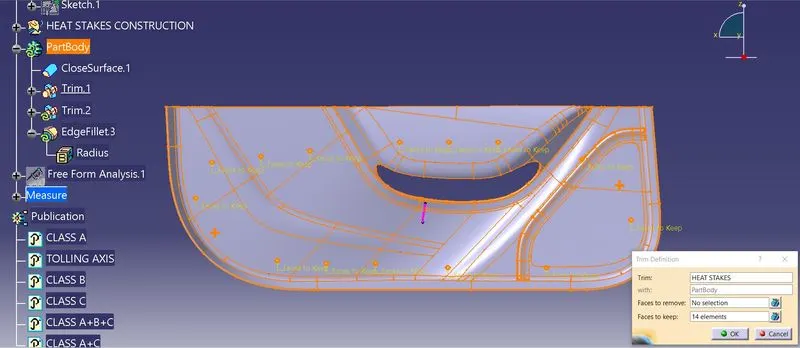
Then assembled together and using Unitrim it is attached to main body.
Draft analysis of 4 Way Locator and Heat Stake:
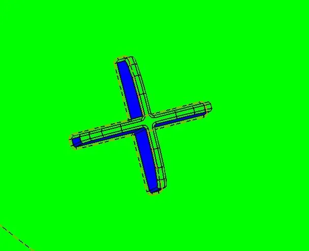
The follow images show the draft analysis of 4 Way Locator and Heat Stake
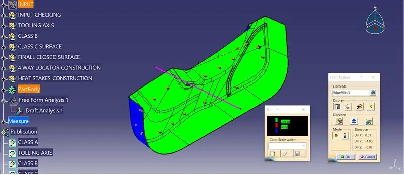
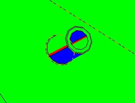
The four way locator clearing the draft analysis
But the heat stakes are having a small region not able to cleat the draft analysis. I considered with skill-lync support team they said it is small region so not a problem.
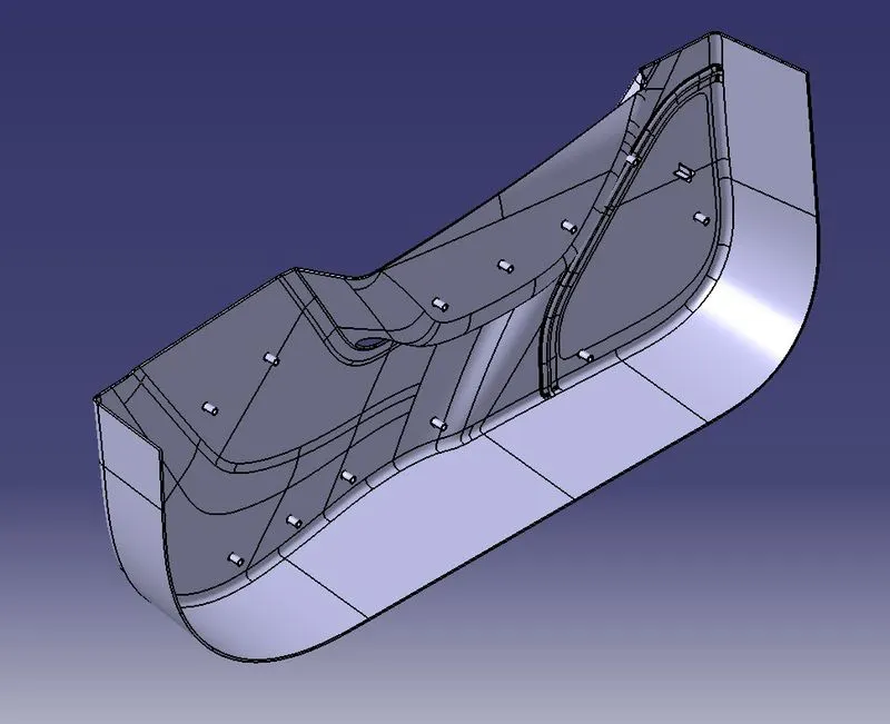
ISOMETRIC VIEW:
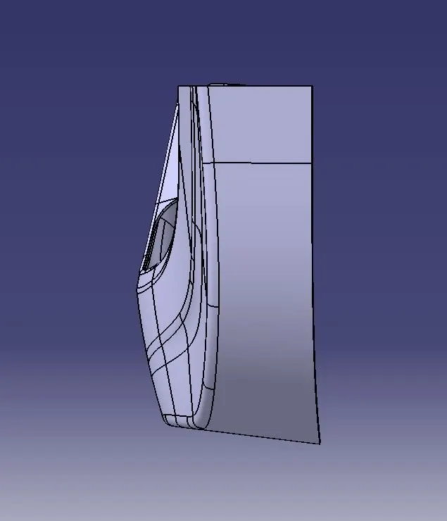
FRONT VIEW:
TOP VIEW:
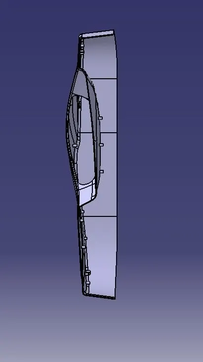
RIGHT SIDE VIEW:
LEFT SIDE VIEW: