Week 9 - Project 1 - Door Trim Lower with Engineering Features
MAIN OBJECTIVE :
Create the Door Trim Lower Plastic component through the given Class-A surface. To begin with, the tooling axis for the given Class-A Surface should be created meeting the requirements of the draft angle and at the end perform the Draft analysis on the model. .
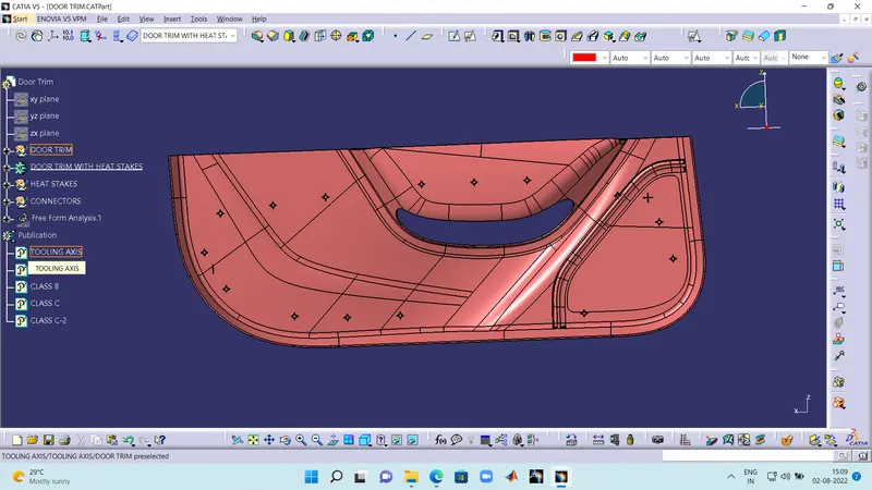
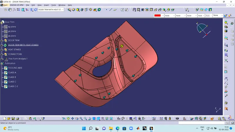
DOOR TRIM WITH B-SIDE FEATURES :
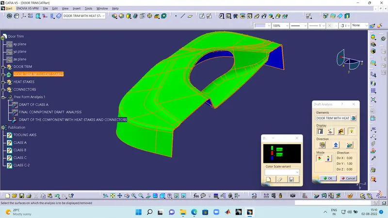
DRAFT ANALYSIS FOR THE COMPONENT WITH B-SIDE FEATUERS :
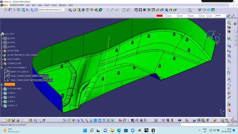
DRAFT OF THE B-SIDE FEATUERS IF GIVEN 0.4 DRAFT :
EXPLANATION :
The class A of a cat part was given as the input. The following steps i have followed to find the tooling axis.
- I extracted a surface on class A and created a point using surface to point command.
- I have took a line in x direction with refferance to the point.
- And named it as the tooling axis.
CREATING CLASS B AND CLASS C :
After creating the tooling axis.
- I have offseted the class B and found that there are some surfaces missing on the class B
- So i have used multi section solid and blend commands to fill in the missing surfaces and complete the class B
- After the creation of class B i have took class A refernace and does a sweep on the edges of class A and hole in the middle
- During joining the sweeps and multi section solids i have found irregular surfaces and i have used trim command to eliminate the irregularity.
- After that i have joined the remaing SWEEPS and made a class C
- Then i have joined class C, class C-2 and class A and trimmed it off with class B to get the final component.
FINAL CAT PART :
Then i have jumped into the part workbench and define in partbody and select closed surface of the Final Component and make it a complete solid to complete the task.
DESIGNING OF B-SIDE FEATURES :
- After the final cat.part i took points on the final cat part to construct the b-side features HEAT STAKES and LOCATOR'S
- I took a point as the referance for the B-surface features. and draw a 4-way locator and 2-way loacator.
- I padded the sketch and made a draft of 0.5 degree and chamfer and fillet the face of 4-way and 2-way locator with 3 mm.
- After that i had fillet the body with 0.25 mm fillet as per industry standards.And assembeled that to the main body
- Then i have a created heatstake on the point that i created previously and translated them to the remaining points and I have used a pase spewcial with referance to the link method to copy paste the heat stakes
- I have add them in one body and added them to the main body
- After that i have done a draft analysis to the component with 0.4 degree draft to get the clearance on the B-side features.
NOTE : The following catpart was given below.