Week -2
MAIN OBJECTIVE :
- Make a Simulink model of Doorbell using solenoid block with the following details:
- Use a thermistor to sense the temperature of a heater & turn on or turn off the fan as per the below conditions:
OBJECTIVE - 1 :
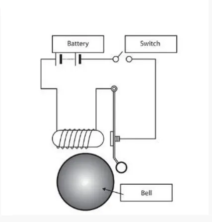
- In above arrangemenet, When the switch is closed the electromagnet receives electrical power from the battery and pulls the metal arm to hit the bell producing sound.
- Create a situation where the switch is closed for 2 seconds and then released. Observe the physical movment of the plunger.
- Assume remaining parameters.
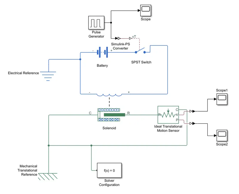
- In the above model the simulation blocks used & their purpose are as follows :
- The pulse generator block generates square waves pulses at regular intervals. The block waveform parameters,Amplitude,Pulse width,Period and Phase delay, Determine the shape of the output Waveform.
- Display signals will be genrated in the scope during the simulation.
- Simulink-PS converter which converts the simulink input signal to a physical signal.
- The SPST switch block represents the Single-Pole-Single-Throw switch controlled by an external control signal vT. If vT is greater than the threshold, then the switch is closed, Otherwise, The switch is open.
- The battery is used to store the electrical sourse for the electrical circuit.
- The electrical block represnts an electric ground.
- The solenoid block represents the electrical characterstics and generated force for the solenoid.This solenoid block represents port R move towards port C.
- The mechanical translational reference block represents a reference point, or frame, for all mechanical translational ports.
- The solver configuration block specifies the solver parameters that ypur model needs before you can begin the simulation.
- Ideal motion translation sensor acts as a motion sensor in mechanical translational systems. The ideal translational motion sensor block represents a device that converts an across variable meassured between two mechanical translational nodes into a control signal proportional to velocity or position. You can specify the initial position as a block parameter.
- PS-Simulink coverter converts the input signal to a simulink outpu signal.
- Working
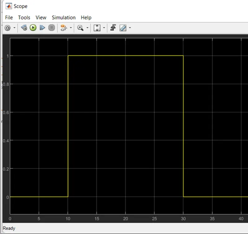
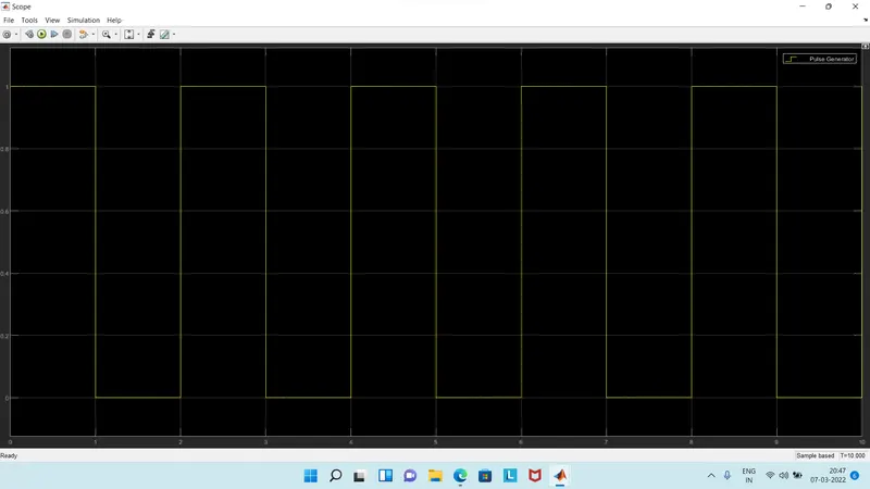
- Pulse generator creates an input signal of pulse with 1 unit amplitude , 10 sec period , hving 50% pulse width with 2-sec delay for the model.
- Then we attach the scope to it get so that we can compare the inputs and otputs of the model.
- Now the input signal is connected to the Simulink-PS converter Which converts the Simulink signal to a physical signal which is then sent towards the SPST switch.
- After receiving the physical signal,the SPST switch compares it with its threshold value if its's greater than it,then it closes the electric circuit, or else it is open.
- After the electric circuit is closed the current is flown from the circuit and then it energies the solenoid conncted to the battery.
- As the solenoid is charged it pulls the port R towards port C of tghe solenoid to understand the position and velocity of the plunger of the solenoid.
- To record its position and the veloicty PS-Converter converts the physical signal to simulink signal and then using the scope block we record it for the simulation duration.
- PULSE VALUE vs TIME
- POSITION vs TIME
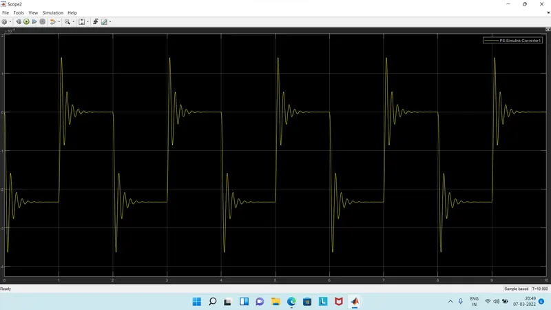
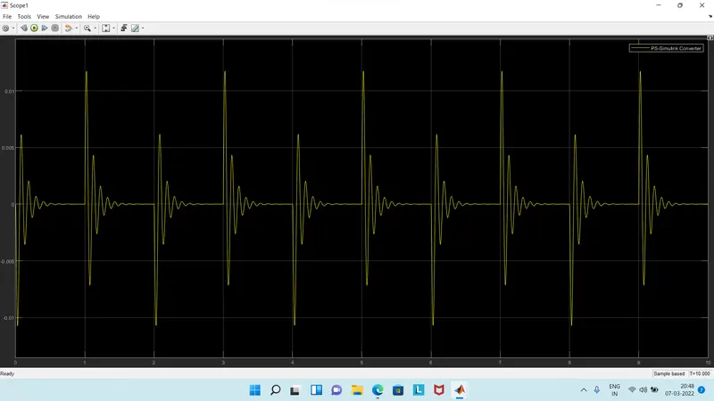
- VELOCITY vs TIME
OBJECTIVE - 2
- THERMISTOR :
A thermistor is a type of resistor whose resistance is dependent on temperature, more so than in standard resistors. The word is a combination of thermal and resistor. Thermistors are widely used as inrush current limiters, temperature sensors (negative temperature coefficient or NTC type typically), self-resetting overcurrent protectors, and self-regulating heating elements (positive temperature coefficient or PTC type typically).
Thermistors are of two opposite fundamental types:
With NTC thermistors, resistance decreases as temperature rises. An NTC is commonly used as a temperature sensor, or in series with a circuit as an inrush current limiter.
With PTC thermistors, resistance increases as temperature rises. PTC thermistors are commonly installed in series with a circuit, and used to protect against overcurrent conditions, as resettable fuses.
Thermistors are generally produced using powdered metal oxides. With vastly improved formulas and techniques over the past 20 years, NTC thermistors can now achieve accuracies over wide temperature ranges such as ±0.1 °C or ±0.2 °C from 0 °C to 70 °C with excellent long-term stability. NTC thermistor elements come in many styles such as axial-leaded glass-encapsulated (DO-35, DO-34 and DO-41 diodes), glass-coated chips, epoxy-coated with bare or insulated lead wire and surface-mount, as well as rods and discs. The typical operating temperature range of a thermistor is −55 °C to +150 °C, though some glass-body thermistors have a maximal operating temperature of +300 °C.
Thermistors differ from resistance temperature detectors (RTDs) in that the material used in a thermistor is generally a ceramic or polymer, while RTDs use pure metals. The temperature response is also different RTDs are useful over larger temperature ranges, while thermistors typically achieve a greater precision within a limited temperature range, typically −90 °C to 130 °C.
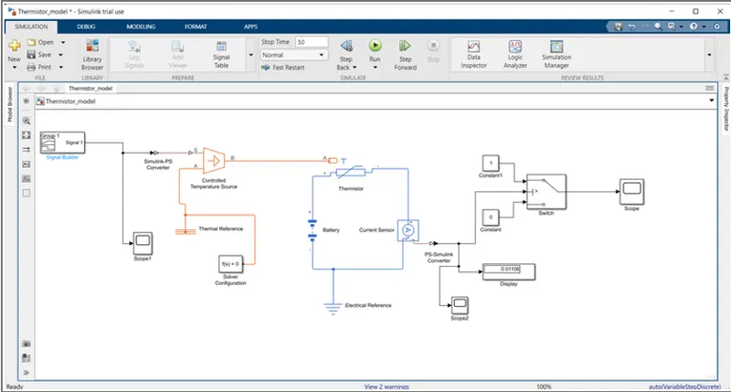
* The below picture shows, simulink model of Thermistor controlled fan.
* Detailed explaation:
- To create a simple thermistor controlled cooling fan model the following Simulink blocks are needed
- Signal builder
- Simulink-PS converter
- Controlled temperature source
- Thermal resistance
- Solver configuration
- Thermistor
- Battery
- Electric reference
- Current sensor
- PS- Simulink converter
- Display
- Constant
- Switch
- Scope
- Thermistor and Battery blocks are taken into the model to represent the thermistor and battery. The positive terminal of battery block is connected to positive terminal of thermistor block.
- Current sensor block is taken, the negative port of current sensor block is connected to negative port of the battery block and the positive port of the current sensor block is connected to negative port of the thermistor block and Electrical reference block is connected to battery, thermistor and current sensor circuit for earthing. Thus, the simple circuit model is completed, now some physical quantities are needed as a signal for thermistor to work.
- In this case, we need a fan to get ON and OFF at different temperatures. So, to provide temperature Controlled temperature source block is used, which will give specified temperature as an output. Temperature signals are needed to provide different temperatures to controlled temperature source block, so the Signal builder block is used, which can send any type signals as inputs. Double click on the signal builder block to set the signals according to the requirement.
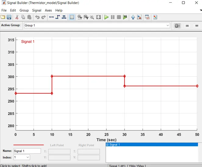
- Above figure shows, how the signals are set in the signal builder block. The above dialog box is opens, first click on “Axes” at the top and then select “change time range” and change the time range 10 seconds to 50 seconds and give the input parameters (time and temperature) as per the requirements (As mentioned in the question) and at the end click on “enter”, now the input signal parameters will be saved and applied. Here Simulink-PS converter block is used to convert the signal builder input signals into physical value.
- Now the port ‘B’ of controlled temperature source block is connected to port ‘A’ of thermistor block and port ‘A’ of controlled temperature block is connected to Thermal resistance block, and this thermal resistance block is connected to ‘Solver configuration block’.
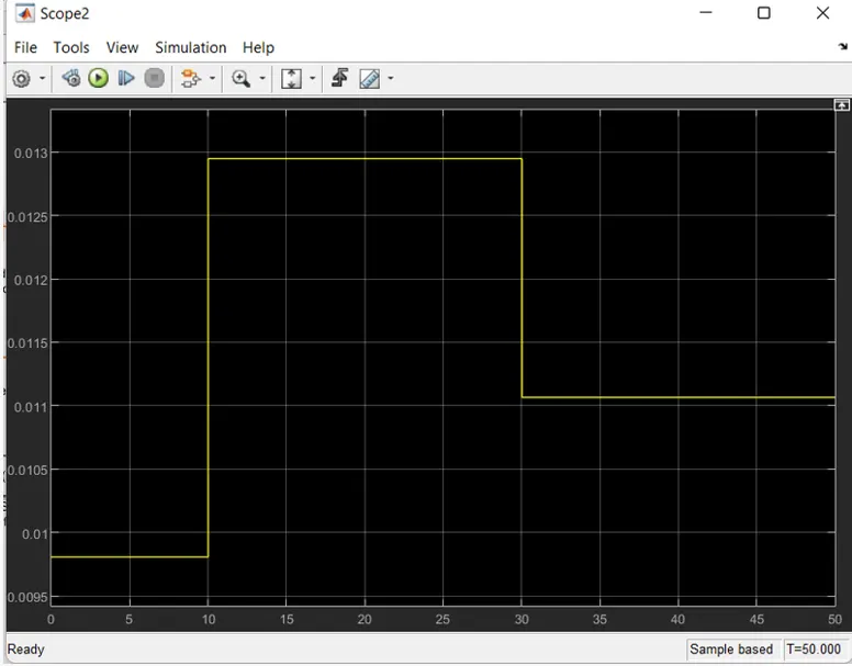
- The output of current sensor block is connected to Scope block, Switch block and Display block. Before connecting to the scope block the PS- Simulink converter block is used to convert the physical value into the Simulink value and the switch block is connected to two Constant blocks. When runs the simulation and double click on the scope block the following graph will be shown, the figure shows how the voltage is changing with change in temperature and we can set conditions for ON and OFF.
- If we observe the graph, from time 0 to 10 seconds the temperature is 293.15K and the voltage is between 0.0095 to 0.01, from time 10 to 30 seconds the time the temperature is 300.15K and voltage is between 0.0215 to 0.013 and from time 30 to 50 seconds the temperature is 296.15 and voltage is above 0.011, from the graph when voltage is above the 0.11 the should ON and voltage is below 0.11 the fan should be OFF. The ‘Switch block’ is used to ON and OFF the fan according to the signals received from the current sensor block.
- The centre port of Switch Block is connected to output of PS- Simulink Converter which gives the voltage values. The top port of the Switch Block is connected to a Constant Block of value '1’ and bottom port of the Switch Block is connected to another Constant Block of value ‘0’.
- When the value from current sensor block is more than the threshold value in the Switch Block, it will pass the value 1 which we have specified in the top port of the Switch Block. If the value from Current Sensor Block is less than the threshold value in the Switch Block, it will pass the value 0 which we have specified in the bottom port of the Switch Block. Here it acts like a transistor in a real time circuit.
- To set the threshold value of switch block, double click on the switch block and change the value of threshold. Switch to be ON only when temperature is 300.15K so the threshold is given as 0.011. So, when voltage gets more than 0.011 the switch will give value 1 as output which means fan will be ON and when voltage gets less than 0.011 the switch will give value 0 as output which means fan will be OFF.
- Now the output of switch block is connected to another ‘Scope Block’ to get the result to display. By double clicking on the scope block we can view the graph. Here we can clearly see that when temperature is 300K the fan is ON and for remaining temperatures the fan is OFF.