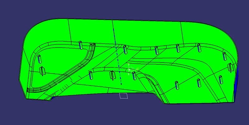
Week 9 - Project 1 - Door Trim Lower with Engineering Features
Front View
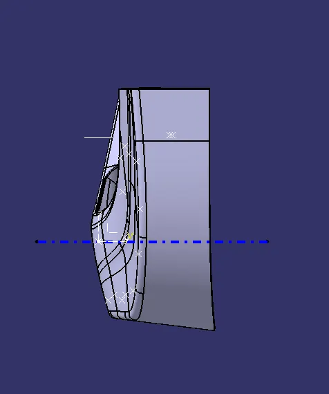
Side View
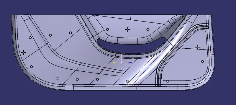
Top View
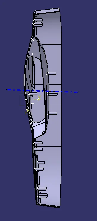
Isometric View
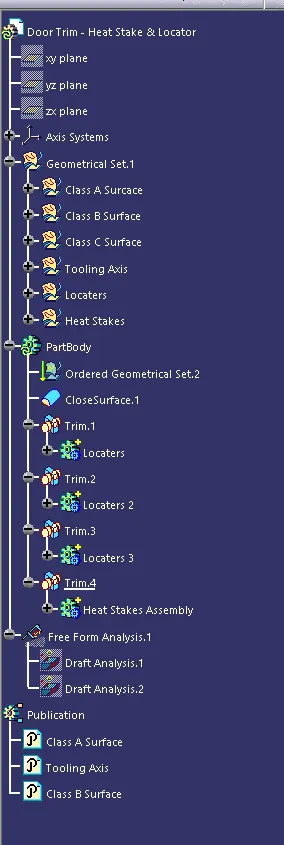
Tree Structure
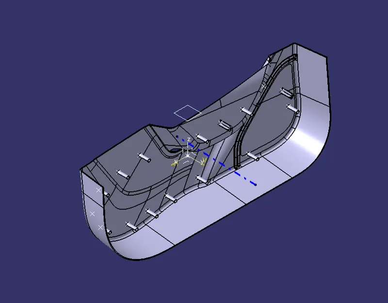
Heat Stakes and Locaters
Aim: To design a Heat Stakes and Locaters for a given part and perform a draft analysis on the given model.
What are Heat Stakes and Locaters?
Thermal Staking is an assembly method that uses the controlled melting and reforming of a plastic studs or boss to capture or lock another plastic or metal component of an assembly in place. Heat stakes are used to fastened the plastic and prevent them from moving. Locaters also dose the same thing and prevent the movement of freedom of the parts.
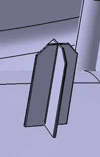
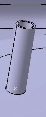
The above are the images of the locaters and heat stakes respectively.
The model in free space will have a 12 degree of freedom as shown in the image,
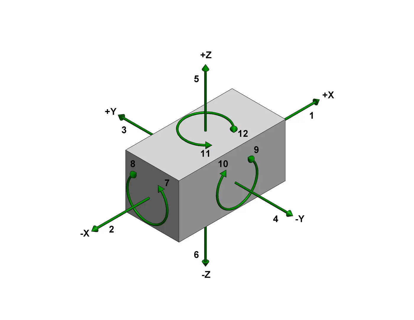
In order to prevent these 12 degrees of freedom the locaters and heat stakes are made on the model to prevent the movement of the model.
The heat stakes are pressed toward the weld parts in order to fix the part onto the other part. The following image will show the process of the heat stakes.
Draft Analysis
What is Draft Analysis?
This analysis done on the CAD product to see whether the model is manufacturable or not. The plastic CAD model that are prepared in CAD software are manufactured in plastic mold, so it is necessary to check whether the part is manufacturable in mold or not. Because is part in not manufacturable in mold then CAD model fails.
What is Draft Angle?
If part has a 90° of draft, then it cannot be manufactured in plastic mold, because on removal of part it may worn or tear as it creates friction on the part removal and will cause damage to the part. The recommended draft angle is prescribed as 3°, but it can be less or more depend on the accuracy needed on the model. For screw holes draft angle should not be more as it will not give perfect fit for the screw.
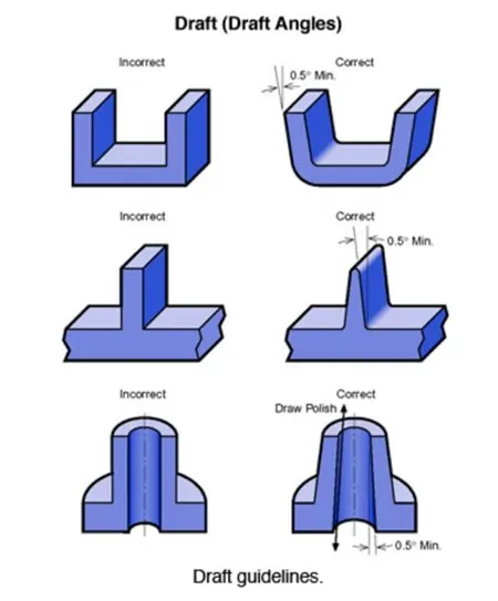
Draft using bisecting lines
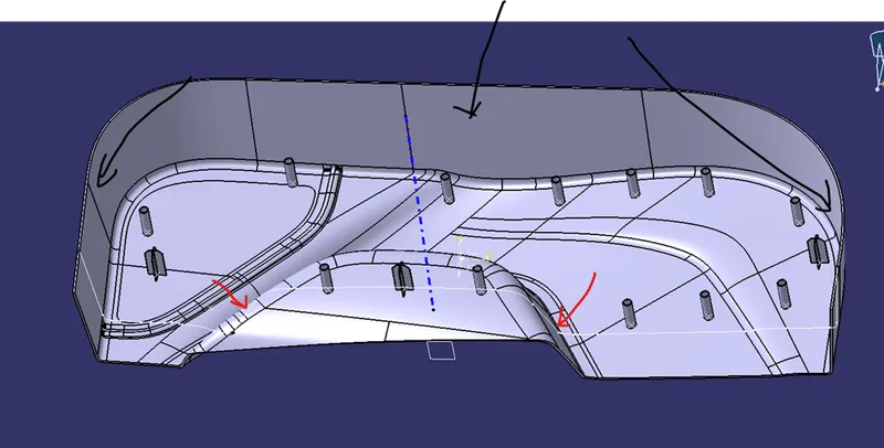
In our model we have two angled walls so, we have to create the tooling axis between them in order to get the proper draft analysis of the model. As we can see in the picture,
- Black Lines: This is straight walls so we don’t need worry about them
- Red Lines: This are the only walls which are angled so we have to create the bisecting line to get the tooling axis.
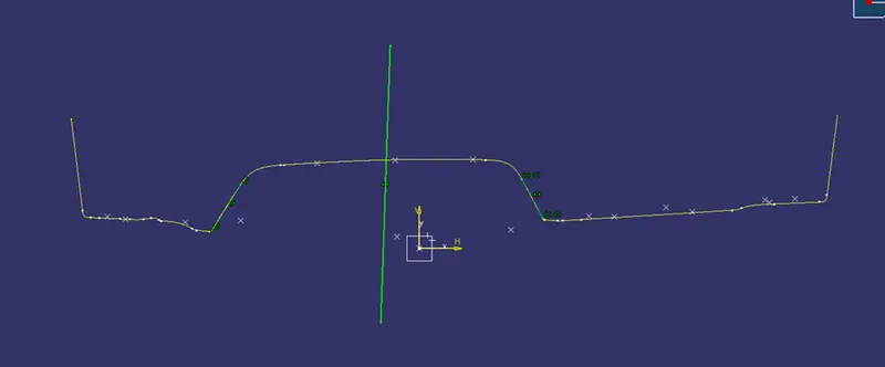
To create bisecting lines, we need to create the plane somewhere on the angled wall in order to get the intersection line so we can create the bisecting line which will be our tooling axis.
Draft analysis of the model: