Week 9 - Project 1 - Door Trim Lower with Engineering Features
Objective: To create surface B and surface C with thickness 2.5mm with considerable draft angle for the given Class A Surface and to create engineering features of Ribs, 2 way and 4 way Locators, Heat stakes and dog houses with their standards in mind.
Part I - Closed Surface from Class A Surface:
Material suggestion:
Polybutylene terepthalate (PBT):
good chemical resistance and bearing and wear properties.
Acrylonitrile Butadiene Styrene (ABS):
good balance of impact, heat, chemical and abrasion resistance, dimensional stablity, tensile strength, surface hardness, rigidity and electrical characteristics.
Tooling Axis:
Core and Cavity Tooling axis:
When a plastic body is created in a molding, the core is moved with respect to the cavity in a linear path. The joining line of core and cavity is called the tooling axis, The plastic component is poured and ejected respectively to hat axis of the core and cavity motion.For, this above challenge to be satisified, the discussed tooling axis must be created for the product, keeping the motion of core and cavity in mind.
Slider Tooling axis:
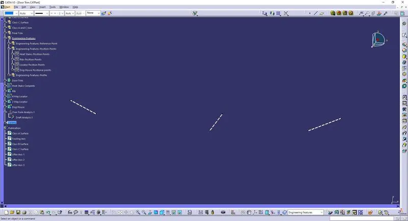
Here the slider tooling axis is used to show the motion of the slider to create the dog houses.
Steps in Catia to add tooling axis:
- An visual analysis by us to be undertaken at every axis plane of X,Y and Z to come up with the suitable plane that holds all the features of the surface A.
- Here the X and Z axis, doesn't suit the above requirement, hence moving to Y-plane we preserve majority of the details given to surface A.
- At first we must create a geometrical set, where it should be renamed as the "Tooling axis".
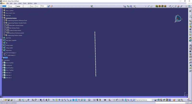
- To Fix Y axis as the tooling axis, we must construct line to represent it.
- For the line creation, we can use the extract option to extract a surface from Class A surface as the reference and using the point option, we must include a point in the centre of the hole.
- Now to draw a line, use the line-direction command, where the previously created point as the starting end, we must extend it on both the sides for a considerable distance, with X-axis as the direction.
- Now to comfortably view the final tool axis, we must publish it separately using publish command in the tools option in CATIA.
Tooling axis snippet:
Slider axis snippet:
Class A Surface:
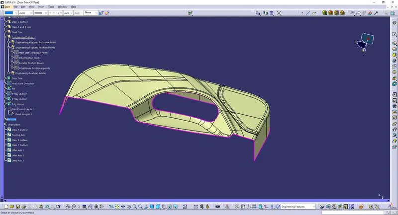
- Starting with the Class A as the input, and required output as the plastic component, we should consider the following:
- The Surface A is the asthetic part of the given component. Hence, changes made over Class A Surface should be avoided.
- Draft Angle must be on the Class C Surface.
Steps in Catia to import Class A Surface as neutral file (STP, IGS):
- Using open option in the catia file menu, the class A Surface file is opened from either IGS, STP or CatPart.
- If it is in IGS format, the surface A must be joined using distance propagation.
Class A Surface snippet:
Draft Analysis:
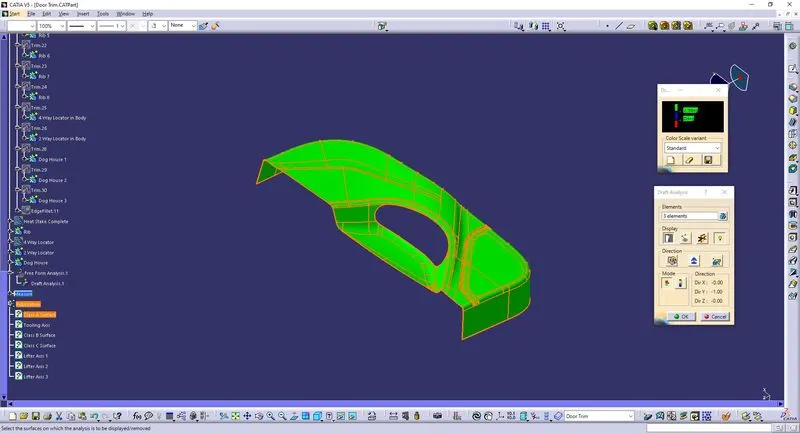
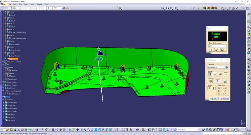
When the final componet is created, the drafting analysis done to ensure the draft angles are given to the surface C is within the standard range of 3 degree. By giving this angle, the plastic component is protected from damage while it is ejected. The colour order of GBR in the order of Green, Blue or Red.
- if the draft shows green colour, then the draft angle is clearing the 3 degree angle.
- If the blue colour is highlighted, then the draft is somewhere between 0 and 3. This area must be studied to make its value close to the 3 degree clearance.
- if the red colour is highlighted, then the draft is below 0 degree, this colour seperates the core from the cavity or slider.
Draft Analysis to the engineering feature, must also be checked.
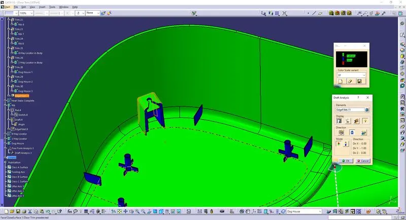
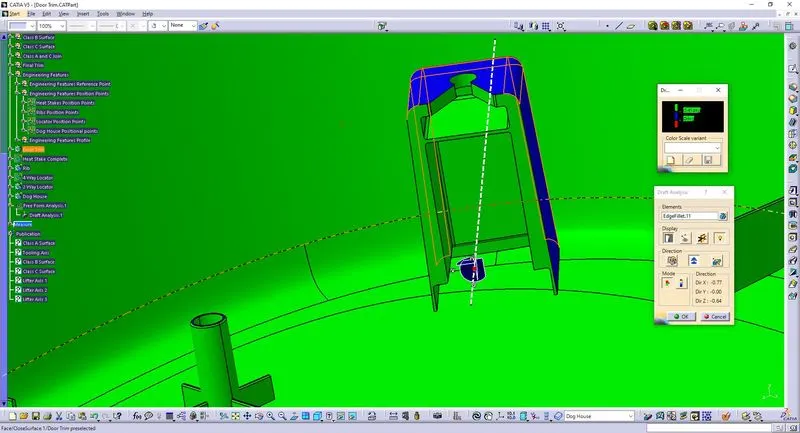
Here, the dog house is the only feature that is made, so the outer draft of 1.5 degree and inner draft of 0.5 degree, should also be studied by changing the green value and the tooling axis with slider axis at necessary positions respectively.
Steps in Catia to Drafting Analysis:
- Add material using the view option to let the draft analysis to run.
- Select the surface or final part body to make it highlighted in the feature tree.
- Use the analysis in the insert option in the CATIA's menu bar, to find the Feature draft analysis.
- Now after selecting the option, two pop window will be displayed, where:
- One has the colour coding, where we must define the colors in the order of GBR (Green, Blue, Red) respectively and set the angle value to be 2.9 for Green, 0 for Blue, and less than 0 as Red.
- Other pop up has several tools for draft analysis, Now from the right most corner of the screen, drag the direction compass and place it on the tooling axis, where the resulting compass aligns with the tooling axis. Now after it gets aligns, lock the compass position using Compass Lock tool.
- To view the draft analysis, select the Surface or final closed body. By choosing it as mentioned, the analysis produces the color coding over the parts where the draft condition/angle satisfies as we mentioned.
Draft Analysis - Class A Surface snippet:
Draft Analysis - Closed Body clearing by Class A Side snippet:
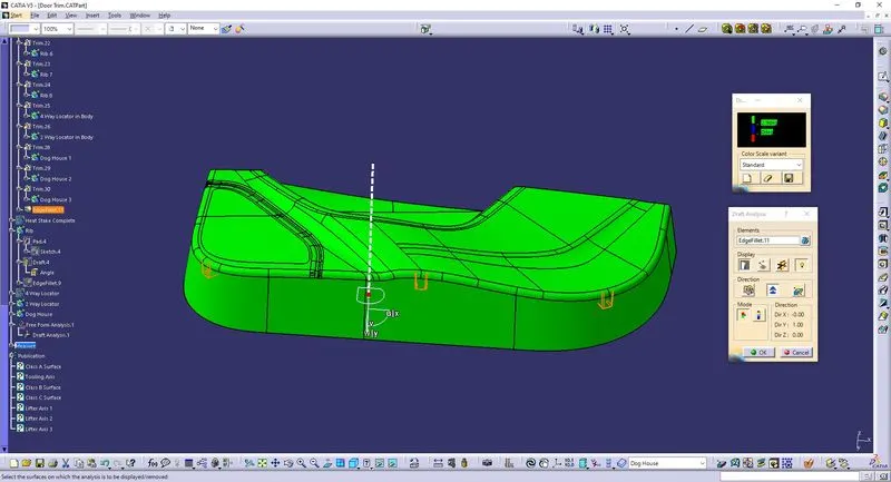
Drafting Analysis - Closed Body with Engineering Features clearing by tooling axis @0.5 draft angle snippet:
Drafting Analysis - Dog House exterior clearing by tooling axis @1.5 draft angle snippet:
Drafting Analysis - Dog House interior clearing by slider axis snippet:
Class B Surface:
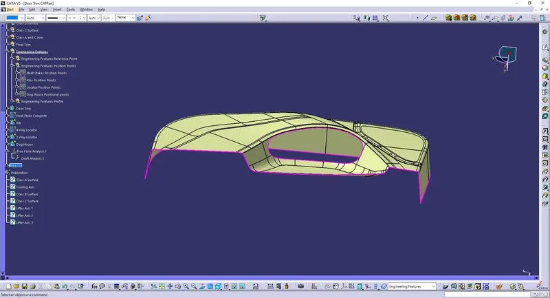
The Class B surface is the other side of Class A surface of the plastic component and where the portion sits on the core.
Make Class B as the sacrificing portion of the component at the core, we ensure the ejector pins motion to push the finished component out of the mold to fall on Class B, again saving Class A from the stress from ejector pins.
Steps in Catia to Create Class B Surface:
- From the given master section by using the measure tool, the thickness of the given model is identified as 2.5mm.
- Now use the offset option to offset the Class A Surface.
- There are some places where the offset fails to add the surface.
- Use the sweep command with reference surface, by sellecting the profile and guide curvce, to recreate the surface lost.
- Now use the join command, to join the surface created.
- Now the Class B surface is created successfully.
Class B Surface snippet:
Class C Surface:
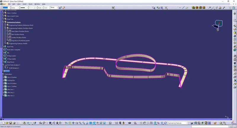
- The Class C surface is the in between portion of Class A and Class B, where the volume is added or in other words, plastic thickness is given here.
- The Class C Surface is given the draft angle of 3.
- To make the component to be easily ejected from the mold, it requires 3 degree draft angle.
Steps in Catia to create Class C Surface:
- Use the Class A surface as the reference and extract the boundaries individually on every sides where the curvature changes using boundary tool with tangent continuity.
- Now use the "swept tool" and "with draft directions" to extrude the boundaries and tooling axis as the guidelines and with draft angle as 3 degrees in outward direction.
- Now use the extrapolate tool to intersect the swept extrudes by selecting the unintersected edges of the swept extrudes to intersect with adjacent swept extrudes.
- Use the trim to join the swept surfaces.
- Save it in a separate geometrical set.
Class C Surface Snippet:
Final Trim:
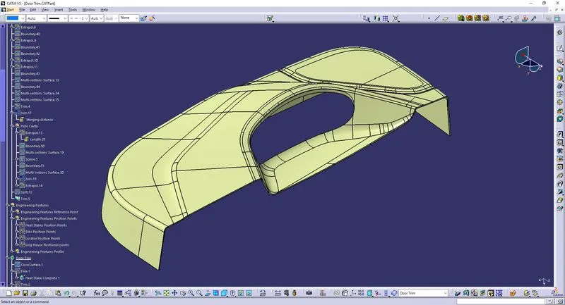
- The resulting surface being formed after joining the Class A, B and C as per the above spoken features specific to the surfaces respectively is done in Final trim.
- This showcases the cavity's and core's design of how the mold should be created.
Steps in Catia to create joined Class A, B and C Surface (closed):
- Use the join command to join the Class C surfaces of boundary and hole swept extrudes with Class A.
- Use the trim command to trim the extended edges of the class C with Class B.
Final Trim Snippet:
Solid Body:
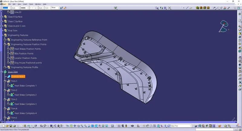
Solid body is the part body created after calling the closed surface command on the Final trim surface.
Steps in Catia to create Closed part body:
- Use the closed body tool in part design to create the part body.
- Run Draft analysis using feature draft analysis from tools, and selecting the part.
Solid Body snippet from Class A Side:
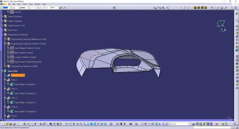
Solid Body snippet from Class B Side:
Part - II:
Engineering Features - Ribs:
Explanation: Ribs are supporting features which adds support to the plastic feature from collapsing.
Design consideration of the Ribs:
Ribs:
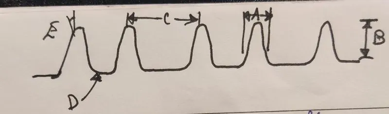
1. A: The Base width of rib = 0.3T(min) - 0.7T(max)
2. B: Rib Height = < 5T
3. C: Spacing between ribs: more than 0.4T
4. D: Radius @ base of rib = T/8 or 0.25mm (max)
5. E: Draft of rib = 0.5 degree or 2 degree
6. Rib root thickness should be 1.4T(max)
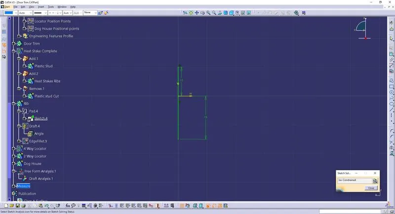
Ribs Design snippet:
Sketch Status:
Engineering Features - Heat Stakes:
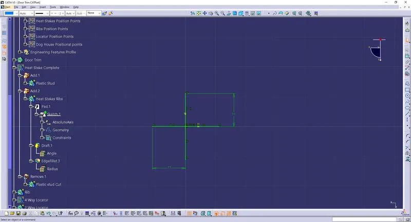
Explanation: Heat Stakes are the features which are used to give permanent joint for the two plastic body.
Design consideration of the Heat Stakes:
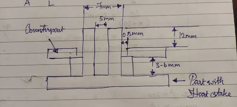
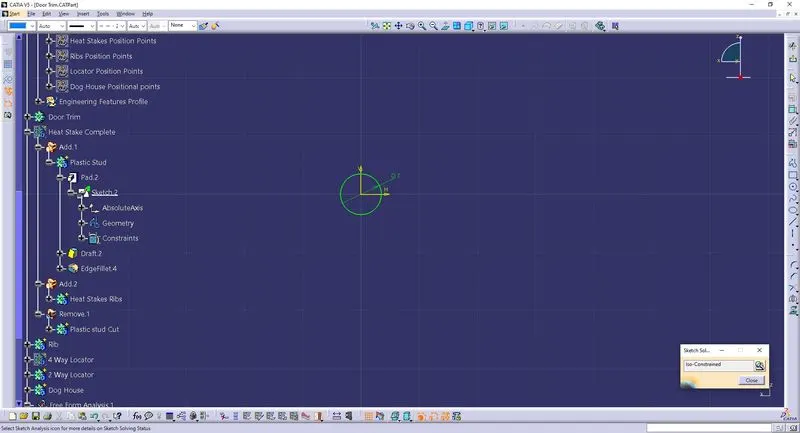
- The Flange must be at the distance of 0.5mm.
- The Heat Stake must extrude out of the flange by 12mm.
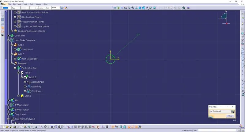
- The inner hole had to be 5mm.
- The Heat Stake had to have a diameter 7mm.
Heat Stakes Design snippet:
Sketch Status:
Heat Stake Stem Profile
Heat Stake Support Rib Profile:
Heat Stake Hole Cut Profile:
Engineering Features - 2 Way Locator:
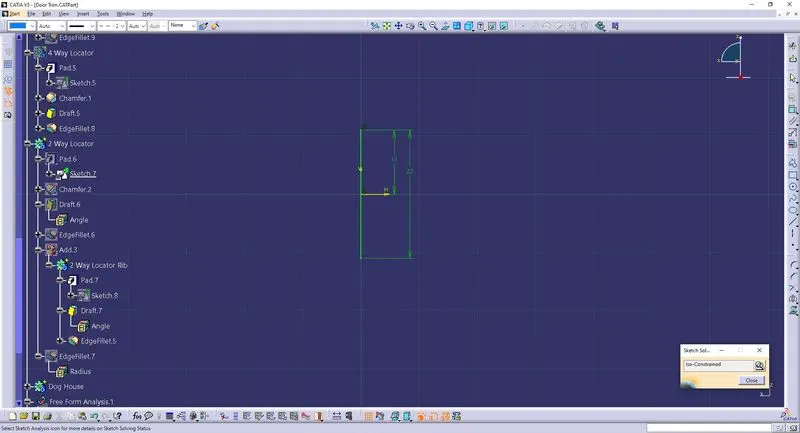
Explanation: It is used to arrest the degrees of freedom where translation along two axis are arrested.
Design consideration of the 2 Way Locator:
- The two way locator had to be more than 3-6mm of the heat stakes's height.
- The degrees of freedom had to be studied, to find where the locator should be given.
- The Locators had to be chamfered to provide a easy path inside counterpart.
- Support Ribs must be provided.
2 Way Locator Design snippet:
Sketch Status:
Main Locator Profile:
Supporting Rib Profile:
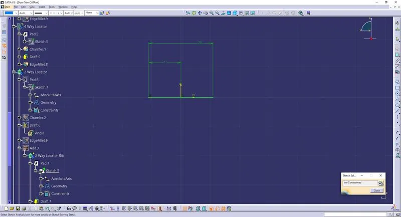
Engineering Features - 4 Way Locator:
Explanation: It is used to constraint 2 Rotation and 1 Translation motion.
Design consideration of the 4 Way Locator:
- The Locator height had to be 3-6mm more than heat stakes.
- The Locator must be chamfered to provide easy assembly with the counterpart.
4 Way Locator Design snippet:
Sketch Status:
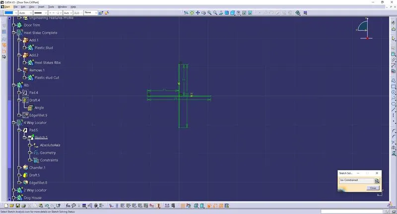
Engineering Features - Dog House:
Explanation: Dog House is a supportive feature that is used to hold screw bosses, snap fits or locators, where the mentioned features required a vertical clearance to combine with another plastic material.
Design consideration of the Dog House:
- The Height of the Dog house must not exceed 60mm.
- The wall thickness of the Dog house must be within the range of 2.5mm.
- Draft angle of the exterior walls must be given 1.5 degree.
- Draft angle of the interior walls must be given 0.5 degree.
- The fillets provided should be more than 0.5mm.
- Width of dog undercut area must be = 3W.
- Height of the undercut should be between 3-6mm.
Dog House Design snippet:
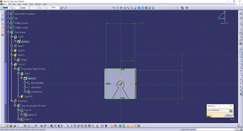
Sketch Status:
Dog House Main profile:
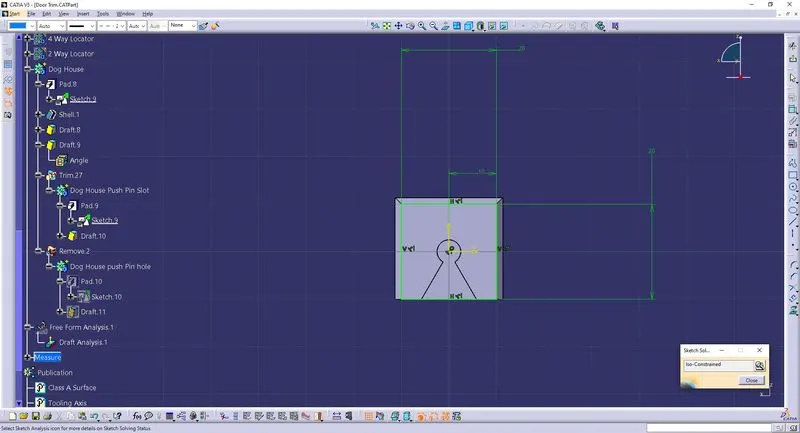
Dog House Push pin slot:
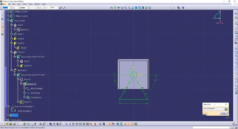
Dog House Push pin slider flange:
3 2 1 principle:
This principle is used to constrain the degrees of freedom.
The numbers 3 2 and 1 states the number of points used to constraint a body's degree of freedom with respect to different planes. Below the 321 princile is explained for the given diagram.
Using 3 point,
- the bodys translation towards X direction is constrained.
- The bodys rotation along Y is constrained.
- The bodys rotation along Z is constrained
So the number three also states the number of degrees of freedom constained.
Using 2 point,
- the bodys translation towards Z direction is constrained.
- The bodys rotation along X is constrained.
So the number two also states the number of degrees of freedom constained.
Using 1 point,
- The bodys translation along Y axis is constrained
So the number one also states the number of degrees of freedom constained.
Application: These are generally used in assewmbly process, where the car components are arrested by its axis to stop it from failing to be in its position after exiting the manufacture plant.
it is also used to stop the degrees of freedom for wasing the manufacturing work for the assembly workers by using jigs and fixtures from small to large components.