Week 9 - Project 1 - Door Trim Lower with Engineering Features
Tolling Axis:-
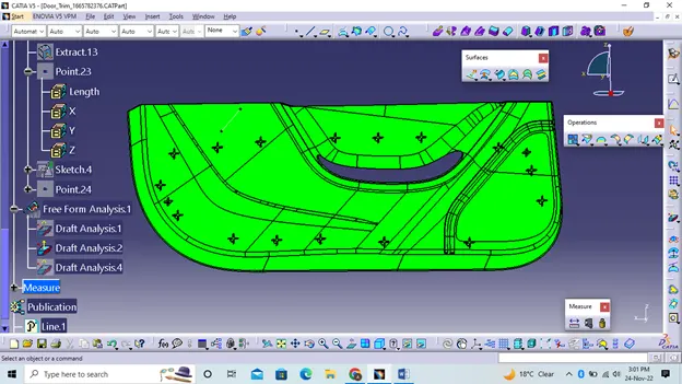
To create the tool axis I extracted the surface from class A and created a point in the middle of the surface using the point command and created a line through the x axis at that point. Now I have done the chamfer analysis check from this line whether the created tool axis is in correct position or not. If in the design, the analysis check the surface highlighted in green on both sides of the surface, the tool axis is in the correct position and direction.
Draft Analysis:-
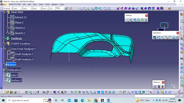
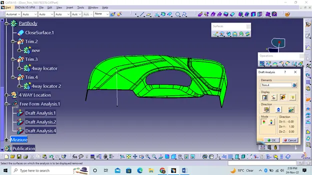
We do a bevel analysis check for the class A surface before creating the solid and creating the features on side B. I initially aligned the compass to the tool axis and gave a 3° bevel angle for the green color in the color bar. If a surface is highlighted in green, the bevel angle is correct for a class A surface. If a class A surface is not highlighted in full green, this may be the reason for the bevel angle of the class A surface.
Class b Surface:-
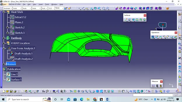
To create a Class B surface, offset the Class A surface inside according to our thickness requirement (here the thickness is 2.5mm, so I offset the Class A to 2.5mm inside). Once the offset is created, we can observe some patches on the offset surface by taking the boundary for the offset surface, these patches are formed due to the rounding on the class A surface. We need to cover these patches using the multipart surface command by extracting the patch boundaries. Once all the patches on the offset are properly covered, bond all the patches to the offset surface to get a replicated surface of the Class A surface.
Class C Surface:-
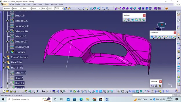
I used the sweep command to create a class C surface relative to the boundary of a class A surface. I initially extracted the boundary of the class A surface with tangent continuity and swept the extracted boundary relative to the surface at a 93 degree angle (for the bevel angle) by 4 mm so that the intersected with the class B surface. Once we have aligned all the boundaries of the class A surface, we extrapolate the retracted surfaces until the two surfaces intersect correctly and trim them to remove the extended extrapolated surfaces to get the correct retracted boundary over the entire surface, including the door trim center hole. Now join the two A classes and pull the border to get a complete C class surface.
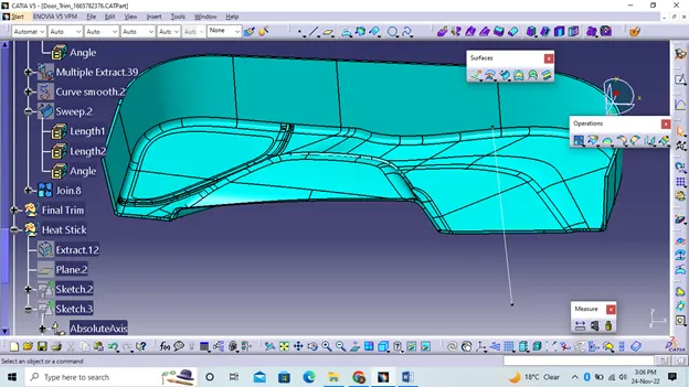
Part Body:-
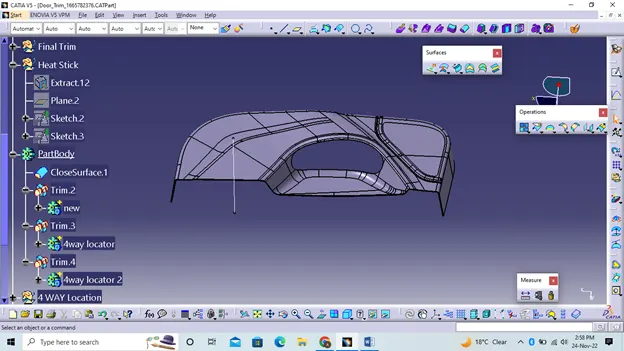
Part Body Draft Analysis:-
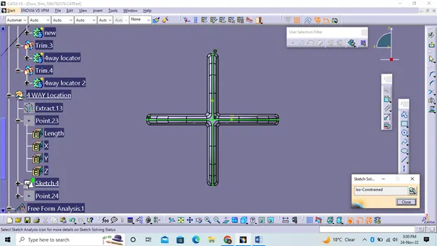
Creation Of Locators:-
4 Way Locator:-
To create the locators I made a sketch on the body. After creating the sketch, I padded it 20mm in height and thickened it to 1.3mm and drew it with 0.5 degrees in the direction of the tool axis. I gave a 5mm chamfer with a 45 degree slope and then gave a 0.25mm radius fillet.
Creation Of Heat Stakes:-
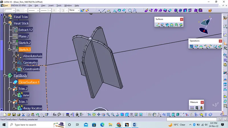
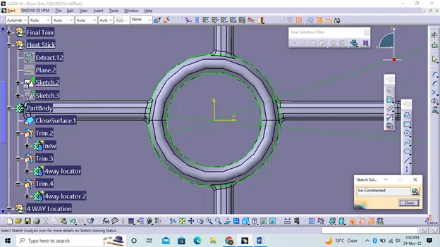
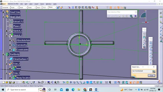
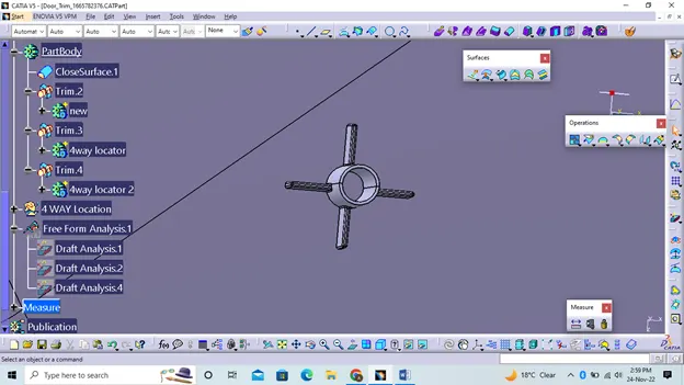
To create the thermal pins, I draw a sketch on the surface. After creating the sketch I backed it to a height of 18mm and on both sides (inside and outside) I gave a bevel angle of 0.5deg and then I gave a rounding with a radius of 0.25mm. After creating the heat pin, I created the ribs for support purposes. To create the ribs I drew a sketch and padded it to 12mm high and 1mm thick. After padding the ribs, I drew 0.5 degrees in the direction of the tool axis and rounded it with a radius of 0.25 mm. Finally, I connect the fins with a heat pin to remove the fins that are present inside the heat pins.
Final Component Draft Analysis:-