Week 9 - Project 1 - Door Trim Lower with Engineering Features
Aim : Create the Door Trim Lower Plastic component through the given Class-A surface. and then Create the Heat Stakes and the locators considering the design rules mentioned in the video for the door applique.
Introduction To Door Trim :-
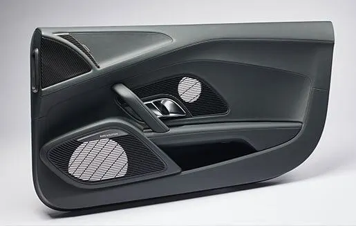
- Door panels serve as an interface between the interior of the car and the inner workings of the door, and between vehicle occupants and the door.
- They are expected to meet a variety of design specifications regarding safety, aesthetics, and functionality.
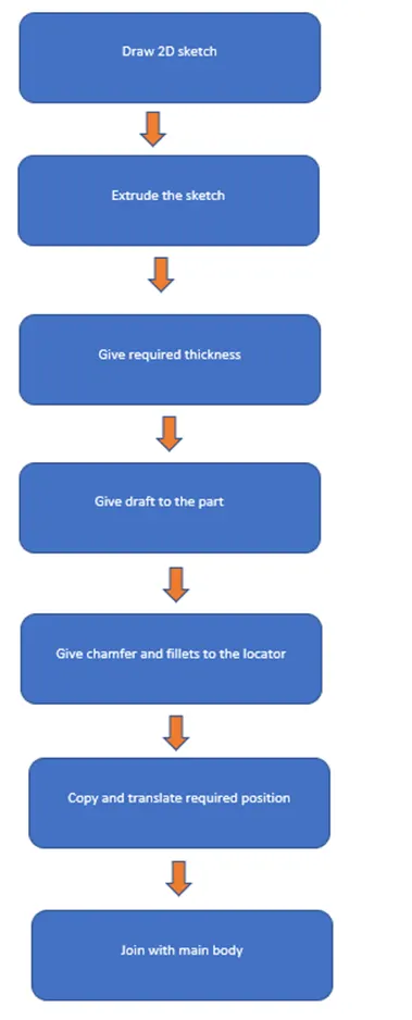
Procedure of Engineering Feature creation :-
LOCATORS:-
Locating pins are the rib like structures on the B surface which are used to position the child part with parent part while assembling.
These locators were placed in the multiple location on the part depending upon the degrees of freedoms which needs to be arrested. They were classified as two-way locators and four-way locators.
Creating engineering features on the B surface
1) Locators creation :- Locators are used to positioned the component in exact location and act as a guide for joining the two component.
- It is used to fix or lock the model with another part. But it is not fully fixed with main part.one side is in moving. It is in Class B surface.
I have created two 4-way locators and one 2-way locator for the given door trim design.
LOCATOR
- There are mainly two type of locator four way and two way locator
- Locators can be designed by following the same guidelines for that of ribs.
- First create the points where we want the locators.
- Extract the base surface of class A from the solid body and create a reference plane with reference to the point then draw the base lines by iso constrained positioned sketch method and chamfer it.
- Extrude the reference line by giving the proper height and thicken it to the required size then give proper draft by considering pulling direction as tooling axis.
- Apply proper fillet to the edges and verify all the dimensions on the rib then add it to the main body.
- Multiple copies of the locator can be created by using copy and paste with special options then translate it by using suitable method.
- By removing the counter clearance body with main body will arrest the degree of freedom of the locators.
Guidelines for creating locator
- Min draft: 0.5mm per side
- Max fillet radius: 0.25mm
- Rib height: less than 5* nominal wall thickness
- Rib should be spaced with a height to width ratio: 3:1 or 2:1
2) Heat stakes creation
Heat staking method is commonly used in OEM to assemble door trims, instrument panels etc.
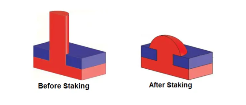
- Thermal staking is an assembly method that uses the controlled melting and reforming of a plastic stud or boss to capture or lock another plastic or metal component of an assembly in place.
- Heat stakes is used to arrest the degree of freedom of locators by 3-2-1 principle in automotive tooling design.
- Heat staking also known as thermoplastic staking is the process of joining two dissimilar materials together.
- In heat staking we use local heating and cooling to raise the temperature of plastic components and allow plastic reforming to be carried out. This reforming can be used in a wide variety of applications.
- Heat staking can be performed using wide range of thermoplastic materials including polypropylene, ABS, polycarbonate and many others.
- The integrity of a thermal staked assembly depends greatly upon the geometric relationship between the boss and the thermal tip.
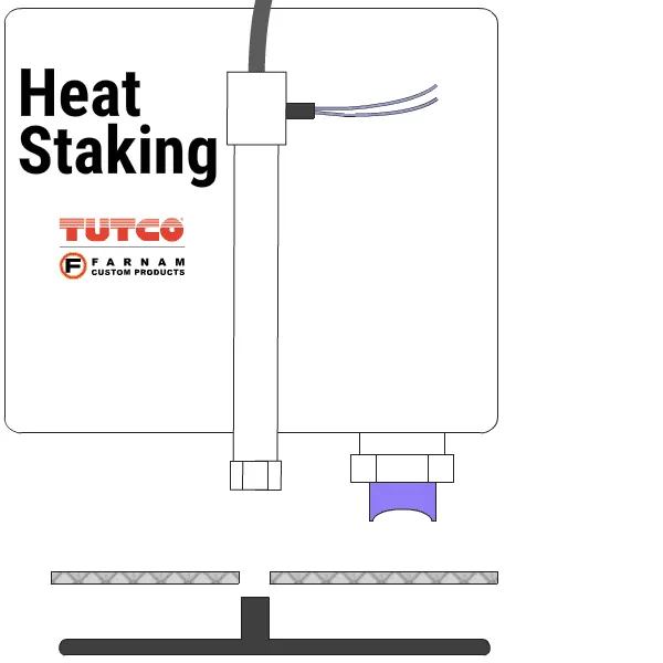
- The heat staking tip is brought into contact with the thermoplastic part to be reformed.
- The heating tip is then heated by direct electrical heating within the tip for a short period of time. The heated tip softens the plastic material and forms the melted plastic into the shape of the tip.
The below image shows a simple animation of heat staking process.
Heat stake Design procedure
- Using positioned sketch, create sketch of the heat stake profile.
- Pad it with reference to the tooling axis.
- Heat stake height should be lesser than the height of locators provided.
- Thickness should be 40% of the component main thickness to avoid sink marks on the A surface.
- Provide draft angle of 0.5 degrees on both inside and outside walls of the heat stake.
- There should be minimum 50 mm gaps between each heat stakes.
- Create more heat stakes by special copying option and translate it to desired points.
- Then union trim them with door trim part body to get the final component.
Advantages of Heat Staking :-
- Heat staking enables similar and dissimilar materials to be joined.
- Local heating ensures that there is no damage to adjacent materials.
- There are many heat stake shapes available through custom designed tools.
- No mechanical vibration.
- Very simple design guidelines are required for success.
Disadvantages of Heat Staking :-
- If formers are too cold, they will strain the stake causing stress, which may also impact breakages leading to failure.
- Temperature control is difficult to achieve with large multiple staking applications.
- The number of posts heat staked at one time is limited by the configuration design of the parts being assembled.
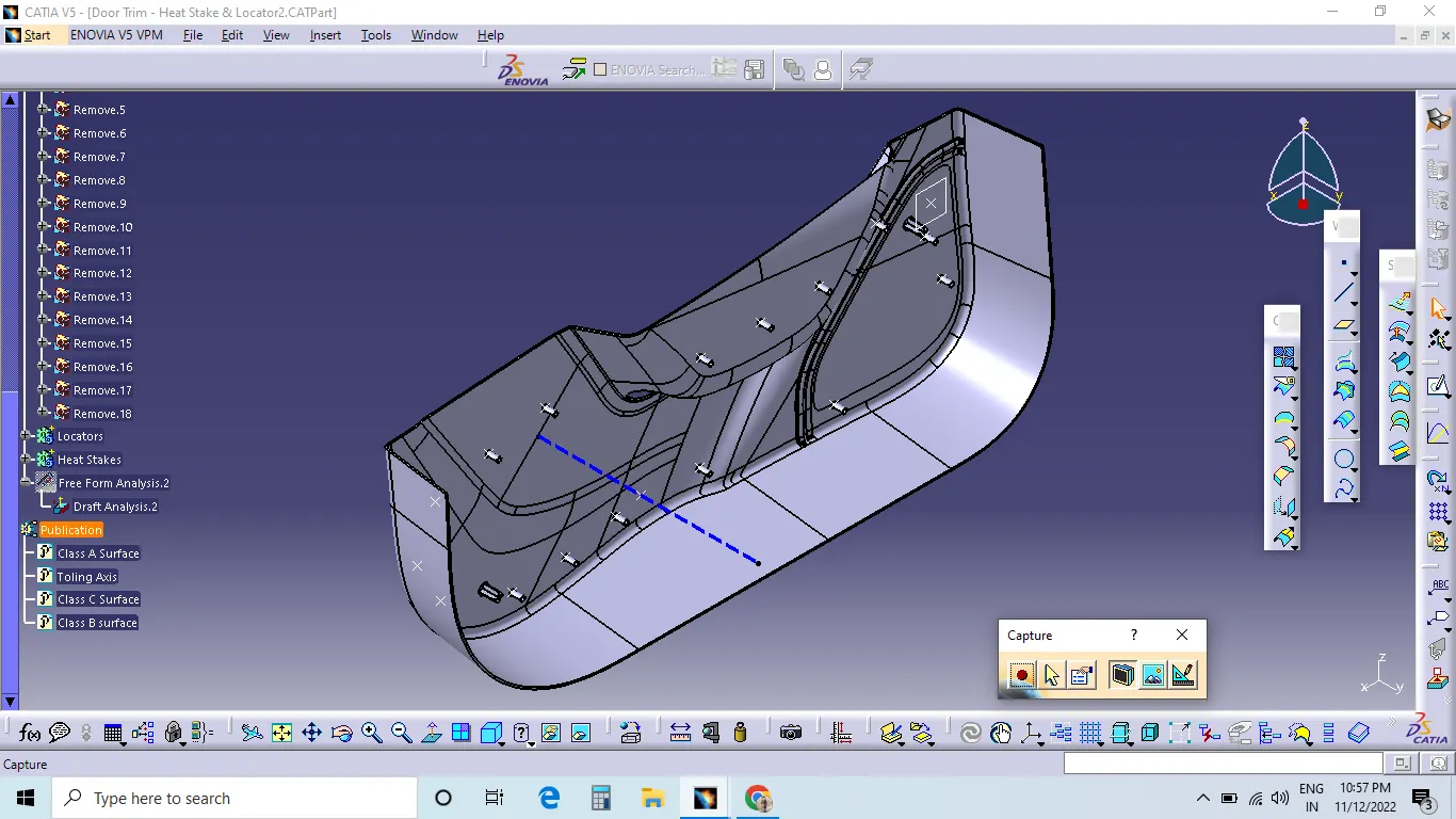
Final Door trim Body with the required engineering features:-
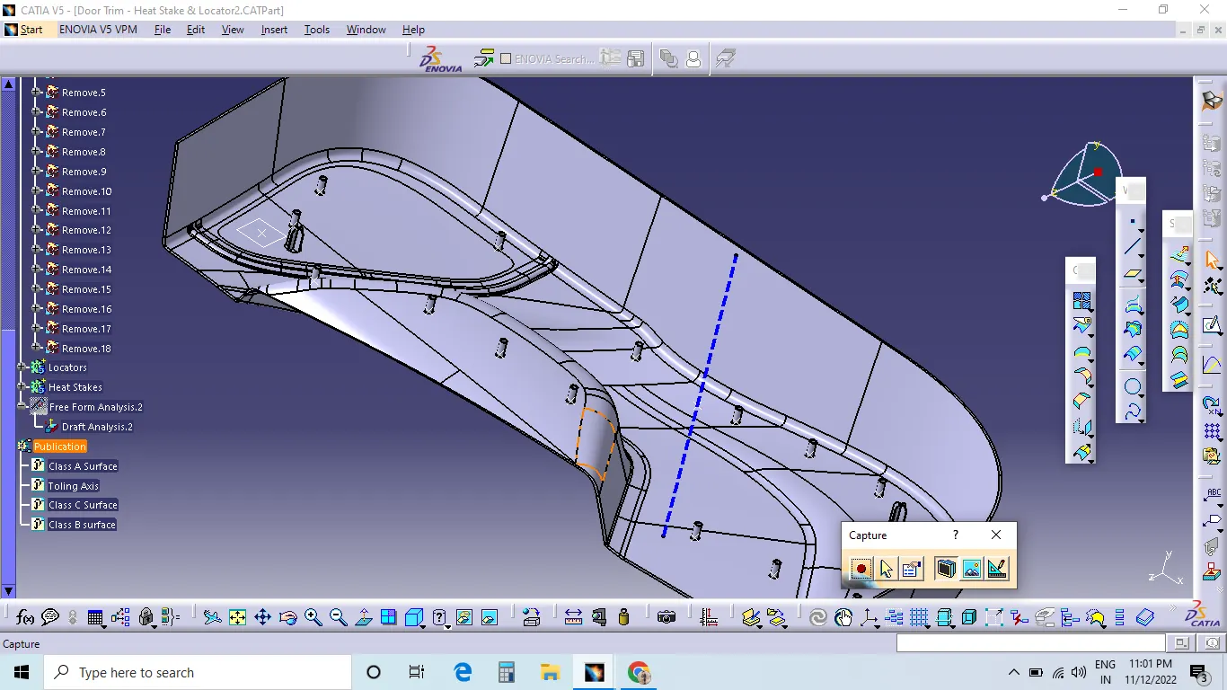
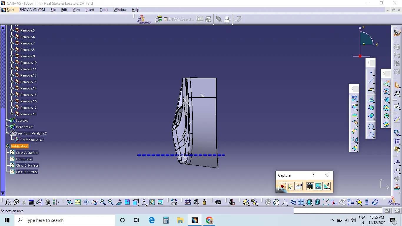
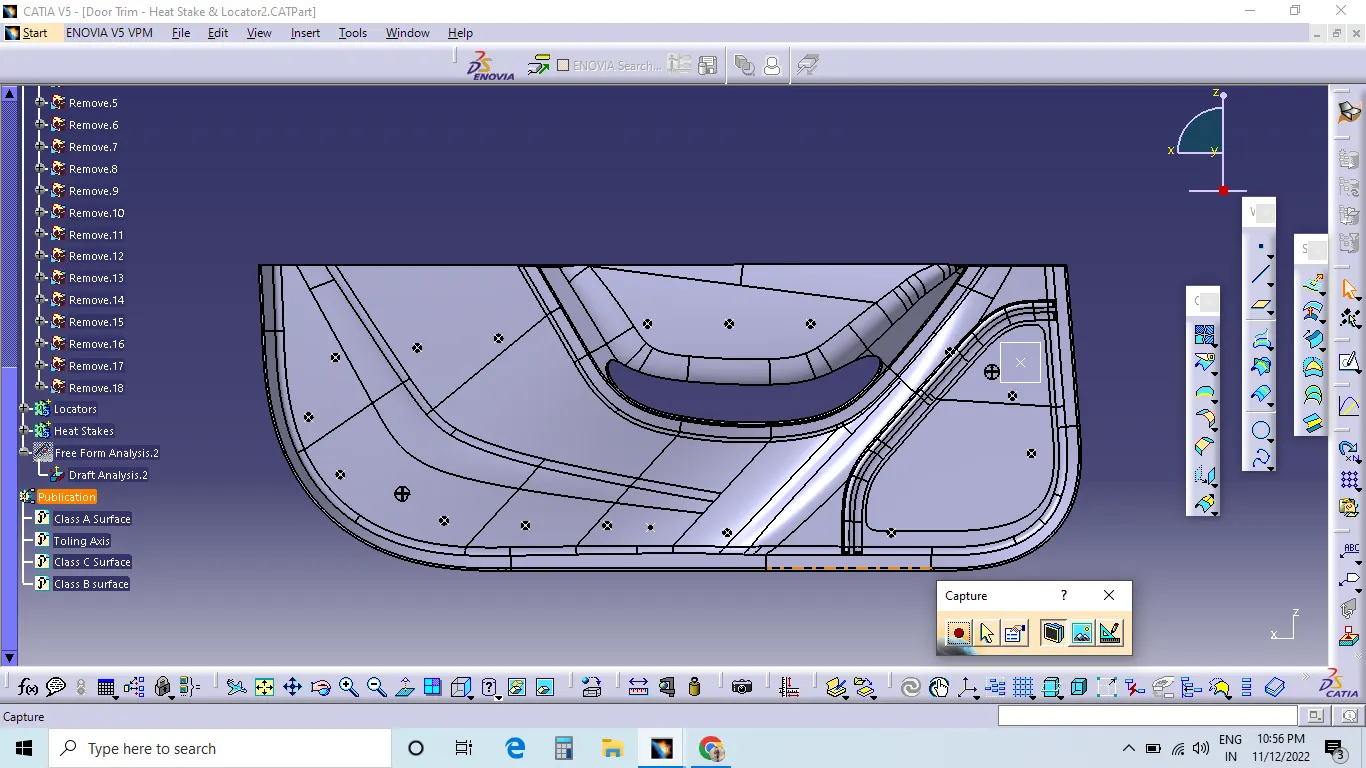
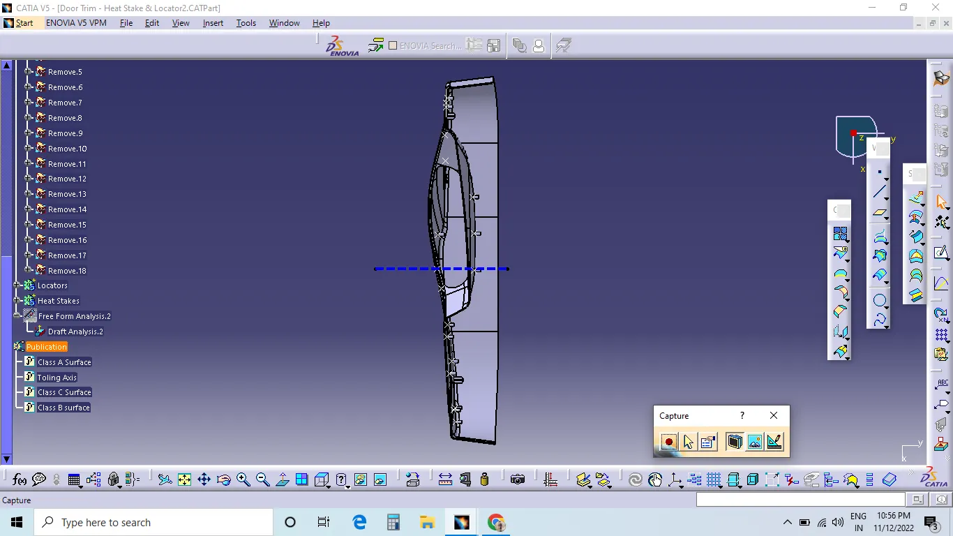
3D Part model in various orientations (Isometric, Front, Side, and Top View):-
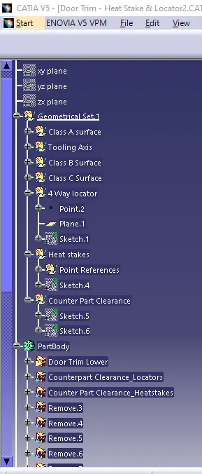
Tree Structure : -
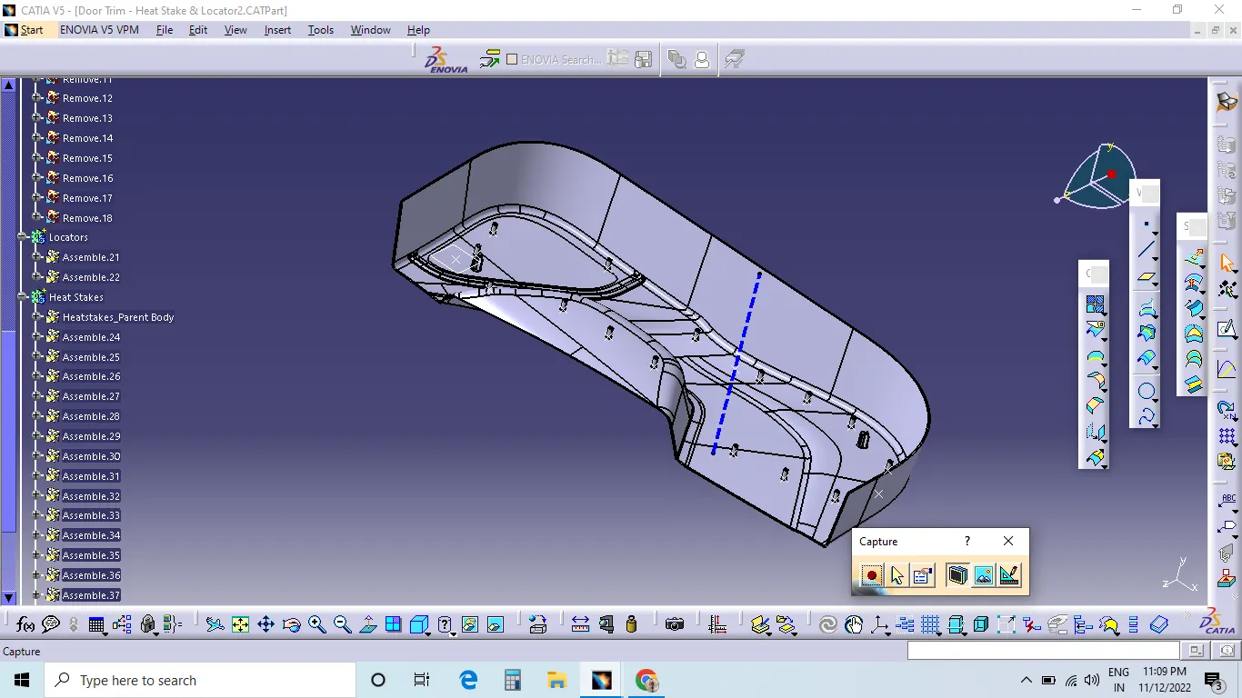
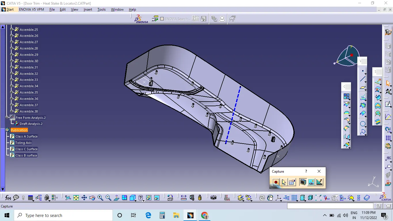
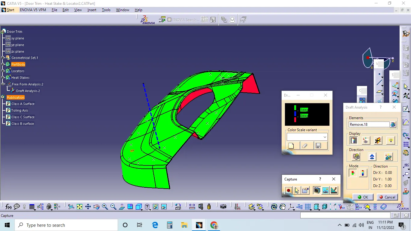
Draft Analysis :-
Conclusion :-
I have created class B and C surfaces using the given class A surface and created enginnering features on the B surface. Draft analysis is successfully performed on both CLASS A surface and Final component.