Week 9 - Project 1 - Door Trim Lower with Engineering Features
Door Trim Lower with Engineering Features
Aim
Create the Door Trim Lower Plastic component through the given Class-A surface. To begin with, the tooling axis for the given Class-A Surface should be created meeting the requirements of the draft angle and at the end perform the Draft analysis on the model.and Create the Heat Stakes and the locators considering the design rules mentioned in the video for the door applique.
Objective
To Design a Door trim lower in CATIA V5 using the given Class A surface and design parameters.
Input data
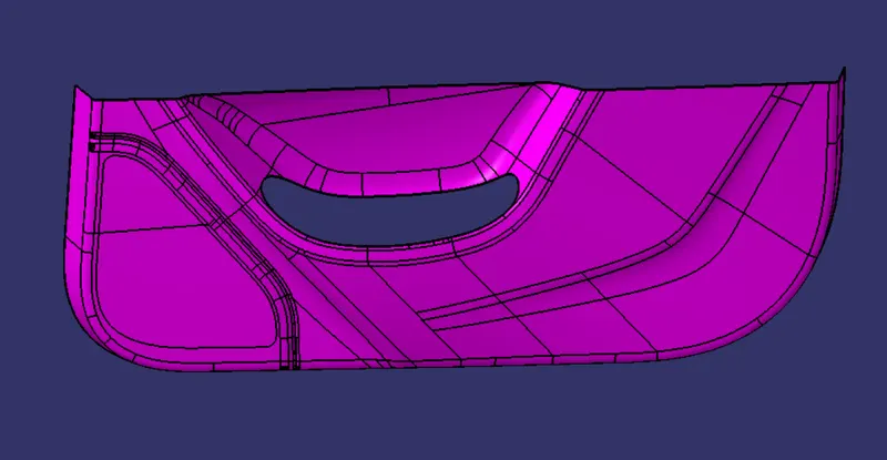
We use class-A-surface as input data.
Tooling direction
Tooling direction in which 2 halves of the mold get separated against each other. for this model am going to use the normal-to-face method instead of bisecting method because my tooling direction is Y axis and i get a flatter surface in Y direction so , am extracted the flat face and create a point at the centre of the extracted surface and i create the tooling axis through the surface along with point which created before. and this method clears the draft analysis so am continuing with this method.
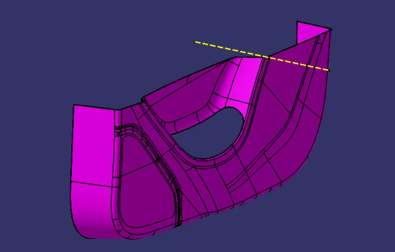
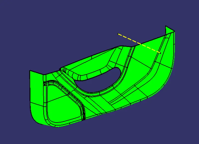
(Draft analysis result of the Class-A surface)
B-Surface creation
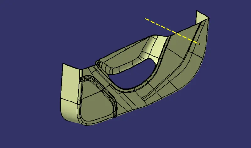
As usual B surface is created using the standard procedure by extract, , extrapolate, join, Trim, split, and offset ,multiple extract, multi section surface commands. The B-surface is created parallel to the A-surface.
Note: The Thickness of the component is 3mm(here we need to offset our A surface to 2.5mm)
C-Surface creation
Class C surface for this component is created using the sweep command. All the ends of the component surface were facing downwards, so the C surface will create perpendicular to B surface.
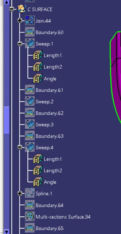
To create a C-surface we need to extract the boundary of the A surface by using the Boundary(point continuity ) "In this design we are unable to perform the previous method . previously we are creating the C-surface in single shot, But here we dont do that eventhough its created in a single shot we need to create a C surface as separate saparate patches then join them together it because of the complexity of the design."
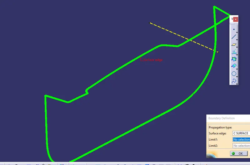
Creating Heat stakes and locators
What is Heat staking?
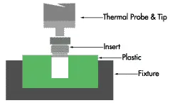
In thermal insertion, or the heat staking process, a metal insert is placed in a cored or drilled hole which is slightly smaller than the insert. This hole provides a certain degree of interference and also serves to guide the insert into place. The heat from the thermal tip travels through the insert to the interface of the metal and plastic. Heat generated by the thermal tip causes the plastic to melt, and as the thermal tip advances, the insert is imbedded into the component. The molten plastic flows into the serrations, flutes, or undercuts of the insert, and when the heat terminates, the plastic re-solidifies and the insert is securely encapsulated in place.
What is Locators?
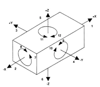
The 3-2-1 method is a work-holding principle where three pins are located on the 1st principle plane, i.e., either XY, YZ, ZX. And two pins are located on the 2nd plane perpendicular to the 1st plane, and at last, one pin on the plane is mutually perpendicular to the 1st and 2nd planes. The aim is to constrain the movement of the workpiece along all three axes.
2-WAY LOCATORS:
2-way mean you prevent movement only at 1 axis on the plane. And generally you have cylindrical pin on the fixture and slot hole at workpiece part.
4 Way Locators
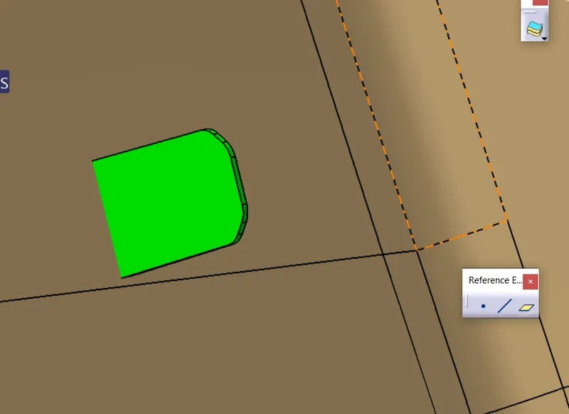
4-way mean you prevent movement at 2 axis (+X, -X, +Y and -Y) on the plane. Generally you have cylindrical pin on the fixture and circular hole at workpiece part.
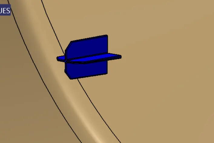
Heat Stakes
Heat staking also known as thermoplastic staking is the process of joining two dissimilar materials together. In heat staking we use local heating and cooling to raise the temperature of plastic components and allow plastic reforming to be carried out. This reforming can be used in a wide variety of applications.
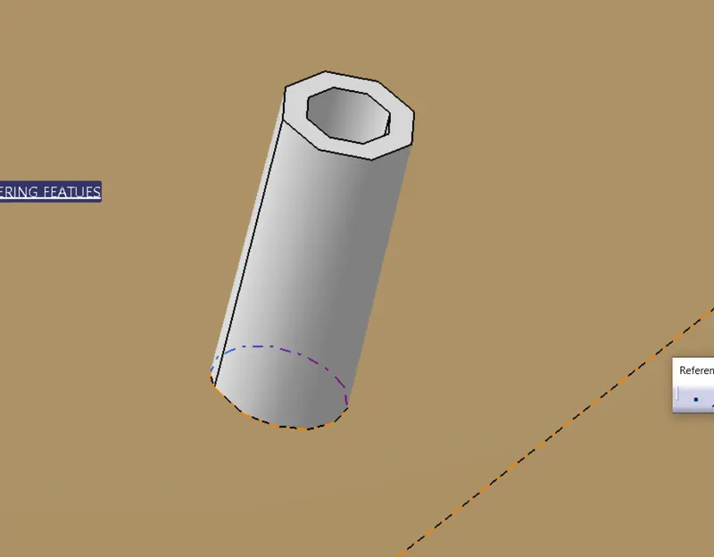
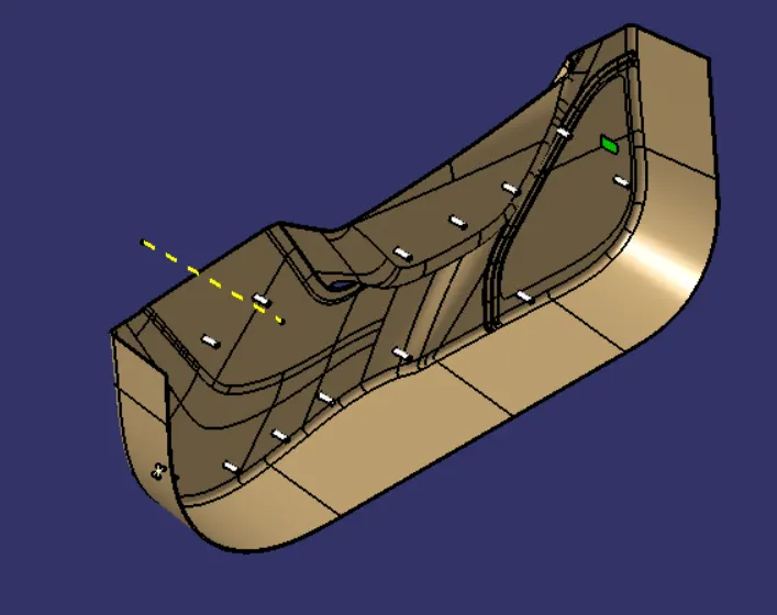
Here am positioning the heat stakes and Locators as per the Master section data
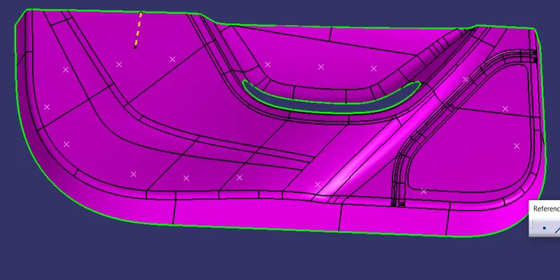
Those highlighted places only we need place our Locators
Features used
- Extract
- Offset
- Trim
- Split
- Swept
- Fillet
- Multiple extracts
- Multi-section surface
- Join
- Extrapolate
- Union Trim Draft
- Pad
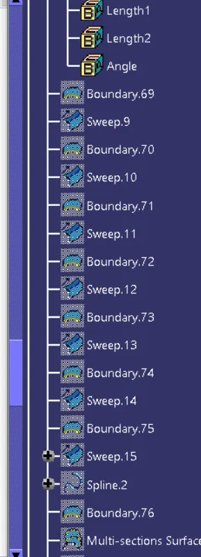
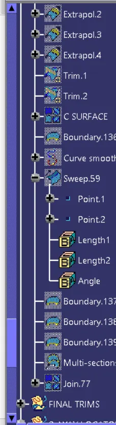
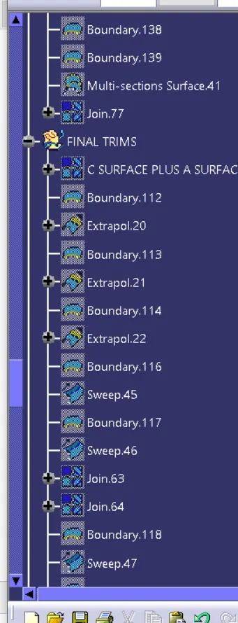
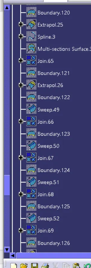
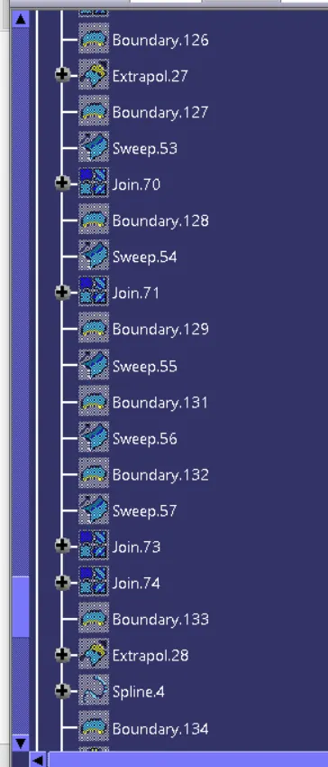
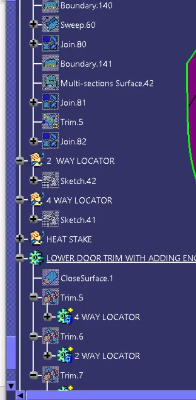
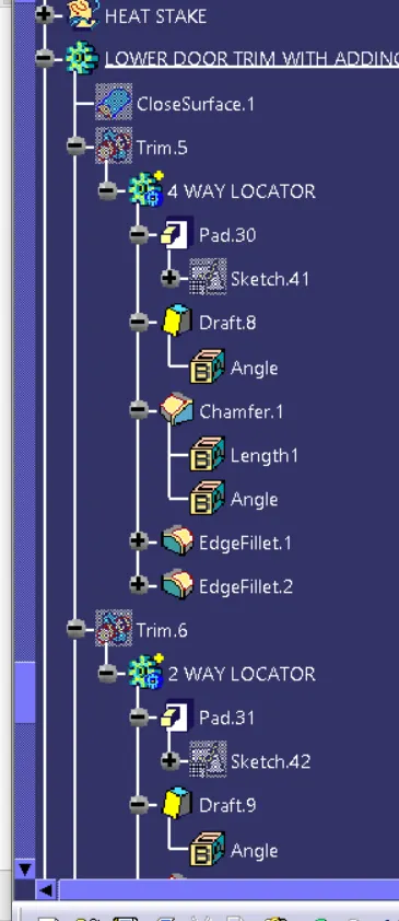
Feature Tree
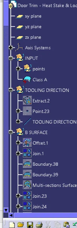
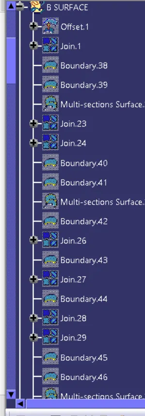
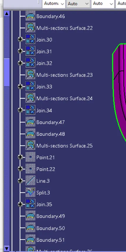
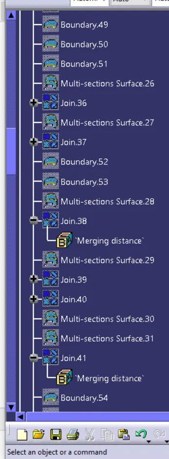
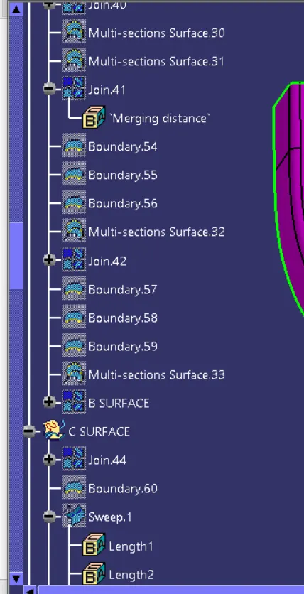
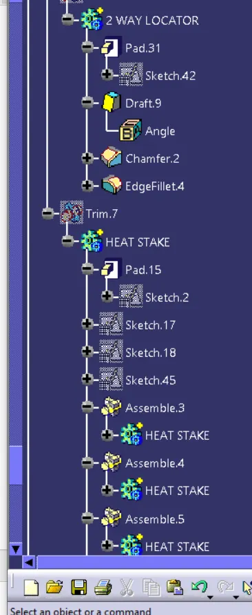
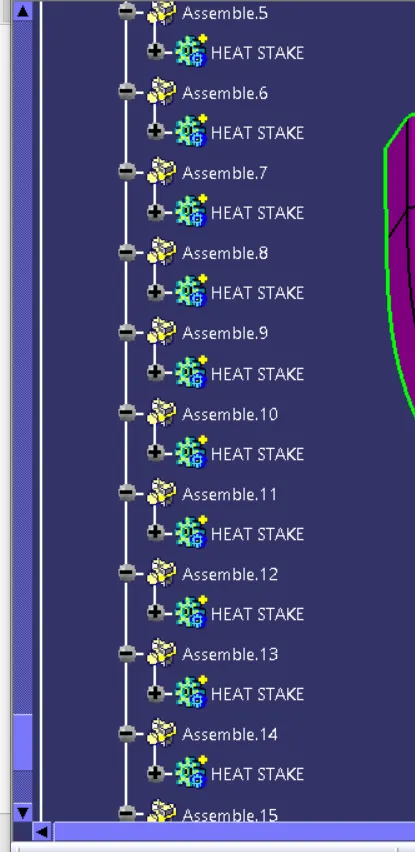
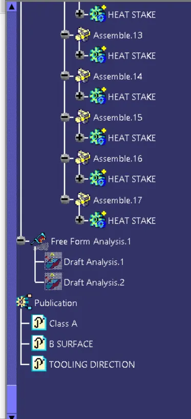
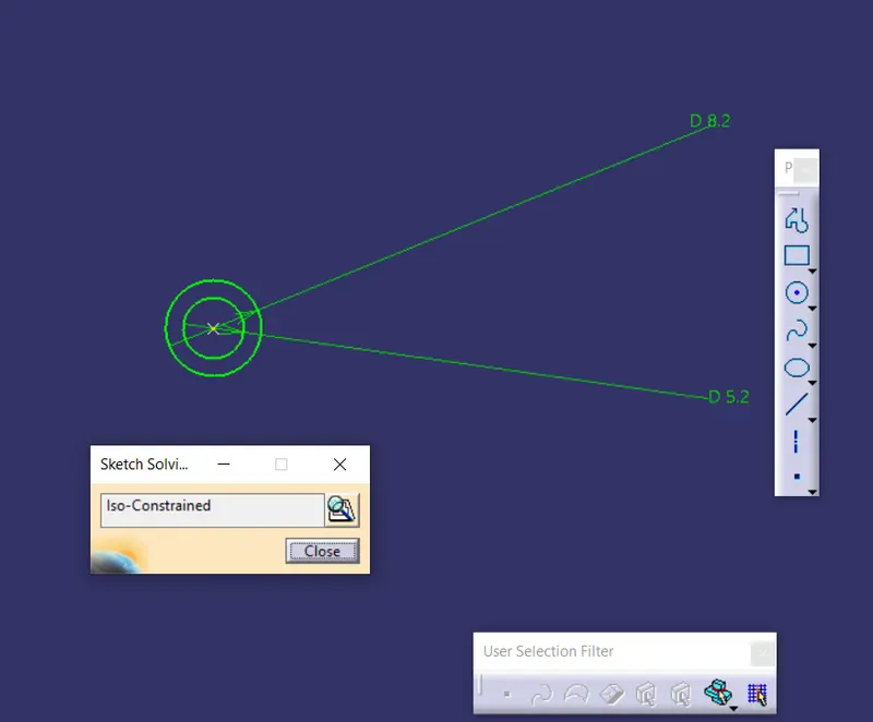
Sketch
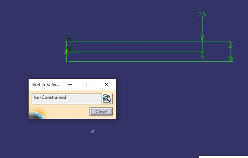
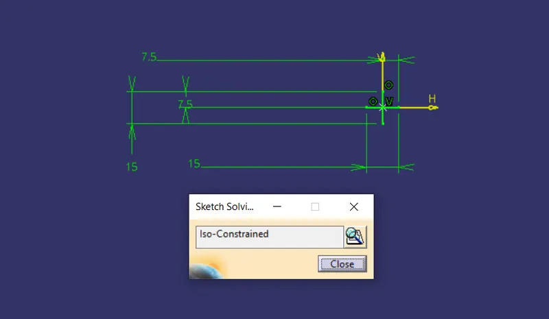
Different views
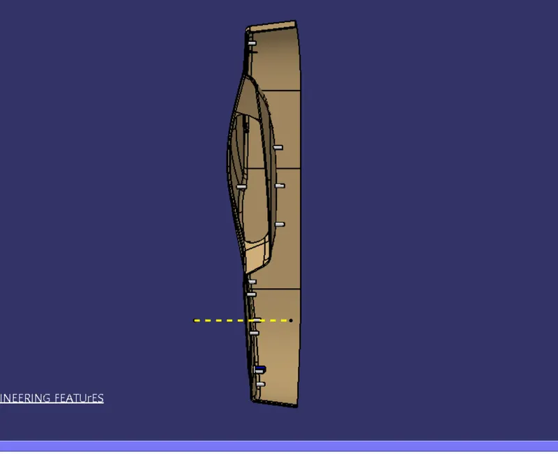
Font view
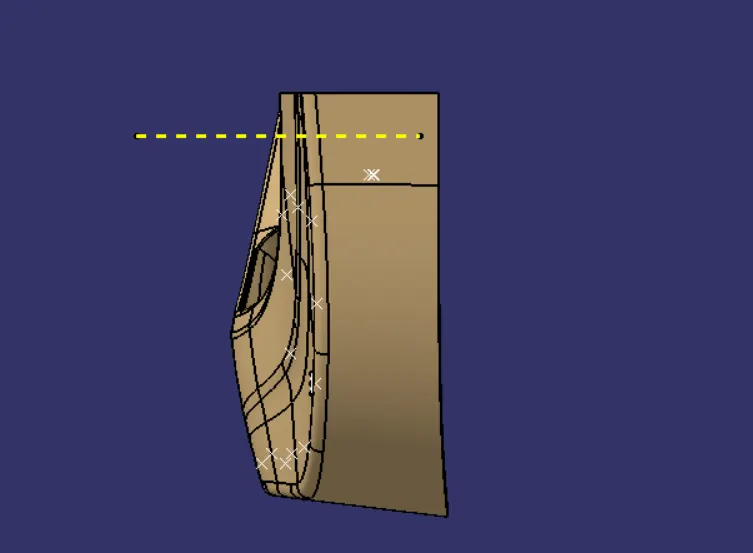
Right view
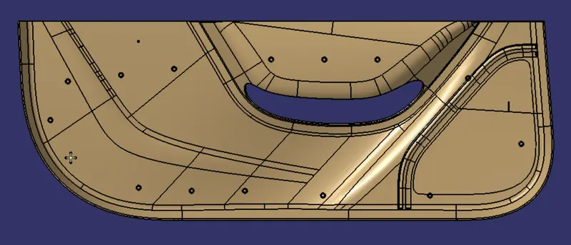
Top view
Isometric view
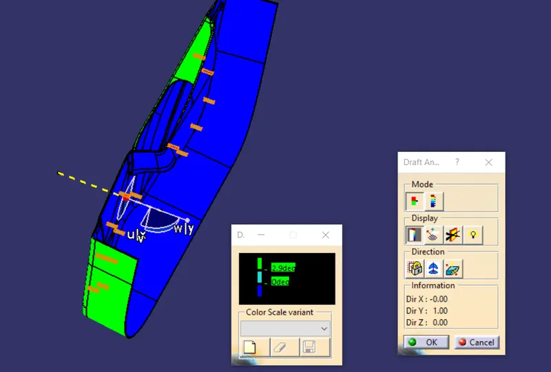
Draft Analysis
The Draft Analysis allows the user to easily analyze a part for a proper draft angle and check to the manufacturability of the component.In this model In this model we have some complex curvatures in the A surface even am giving 3 degree draft angle for the C surface still it creates some complexity it will refelects in our draft Analysis we can't do anything for this kind of problem its happens sometime. Solution for this problem was give some suggestuin for Class _A -Surface engineers to make some changes in A surface then you can proceed furtherly.As you can see the draft analysis heat stakes are showin 0 degree we dont worry about it heats stakes and locators gets cleared with the core side.
Conclusion
I have successfully completed the Door trim lower design with Engineering Features challenge by using CATIA V5.