Week 9 - Project 1 - Door Trim Lower with Engineering Features
DRAFT ANALYSIS REPORT OF DOOR TRIM WITH LOCATOR AND HEAT STEAKS.
STEP 1.
Examination of class A
STEP 1:- using boundry command checked for any non intersecting surfaces, if found any should be done using appropriate commands.
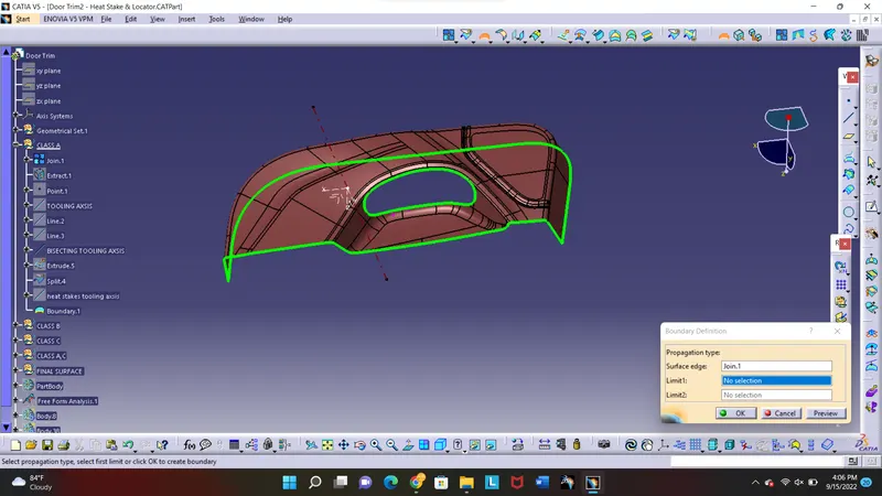
STEP 2:- using join command for creating single surface to work on, for reference for CLASS B , CLASS C .
STEP 2.
Draft analysis of class A,
STEP 1 :-
CREATION OF TOOLING AXSIS
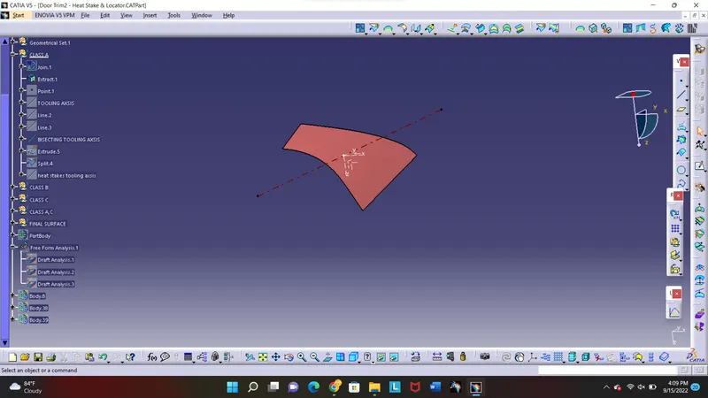
extract any surface of class A as shown in fig.
creat point on surface , and then take line normal to surface , actual tooling axsis should be normal to surface only because most of machinery available have only vreticle tooling axsis and horizontal axsis tooling direction.
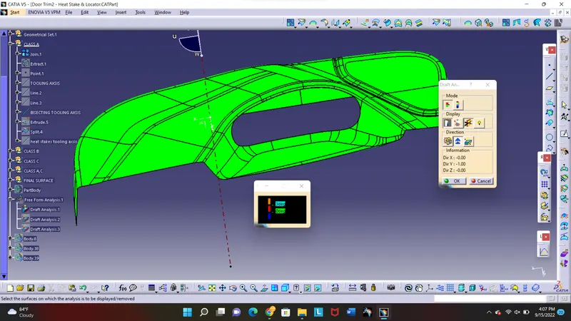
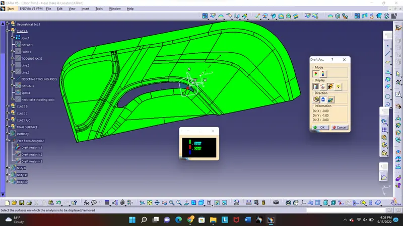
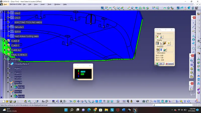
STEP 2:- insert draft analysis , place compass on tooling axsis and define the direction, and again place compass on tooling axsis and click on surface, following fig explains the process.
STEP 3:- analyse the componant clearing the draft analysis or not,
in given class A green colour shows positive angle of draft analysis and red colour shows negative draft angle ,
in given class A surface, shown in fig.
STEP 4:- check for clearance of draft, in this given class A cleared the draft analysis as shown.
STEP 5:-
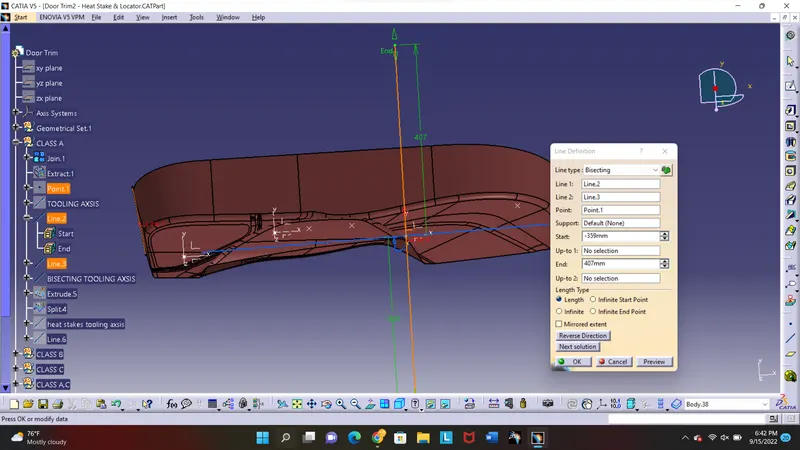
CREATION OF BISECTING TOOLING AXSIS.
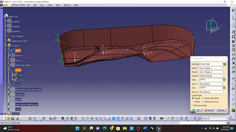
draw refrance line for bisecting tooling axsis.
STEP3.
CREATION OF CLASS B,
STEP 1:- take offset of class A of 2.5mm .
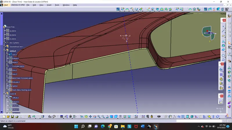
this is offset of class A .
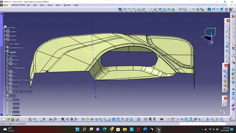
STEP 2:- check for gap and other faults in offset not all surfaces get offset some might have error.
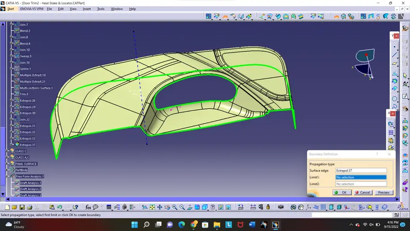
in this offset we got some gaps and non joining portions as shown below fig.
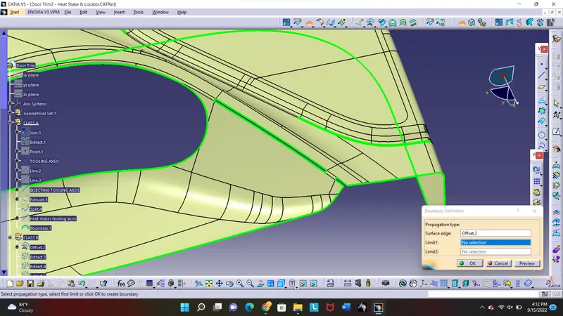
gereen lines shows bounday and open gaps.
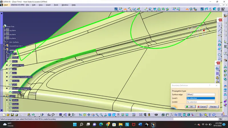
STEP 3:- using commands needed for patch work and joining surfaces.
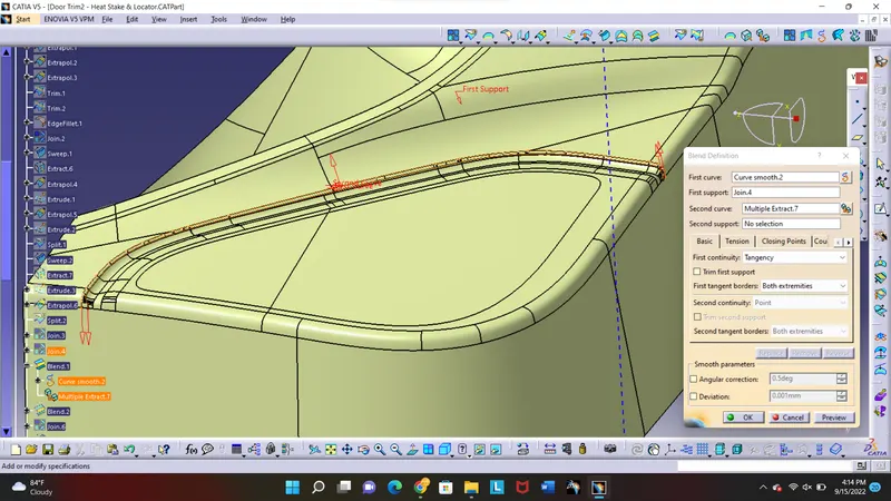
given below is part of surface which has slot in it , using blend command this patch can be filled.
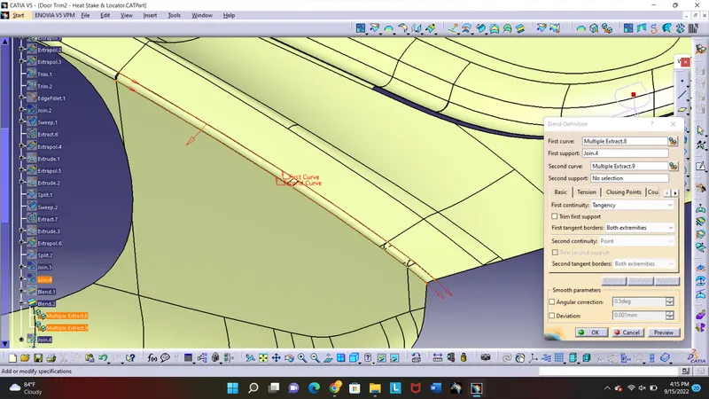
final surface of class B ,check using boundary command .
STEP4.
CREATION OF CLASS C.
STEP 1:- class C is created with given class A, by using swep command as shown in below fig.
extract boundary using boundary command using class A for swep operation.
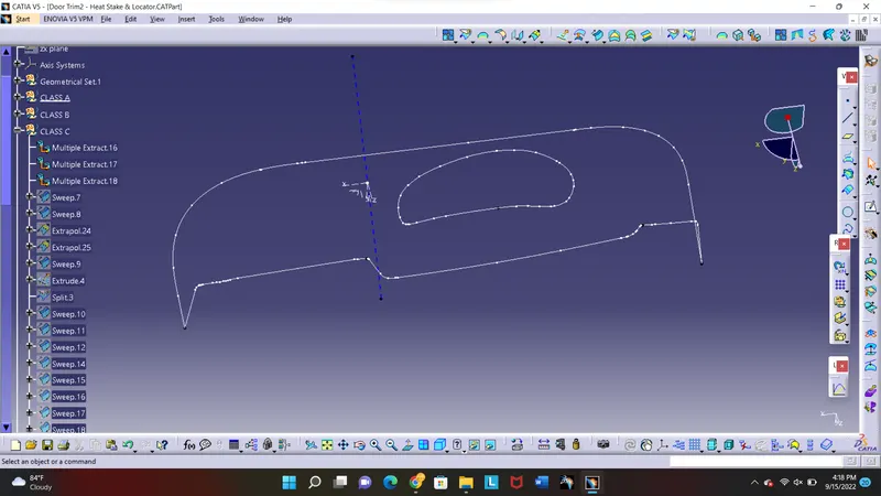
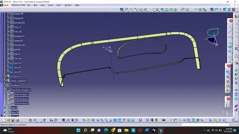
STEP 2:- use swep operation, in swep operation bottom part of surface is sweped at 93 degree with direction of surface,
and front face is sweped with draft direction of 3 degree .
FINAL CLASS C SURFACE.
STEP 5.
CREATION OF CLASS A,C
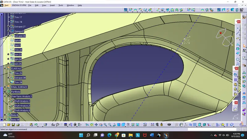
STEP 1:- joinin class A and created swep with join command to creat class A,C
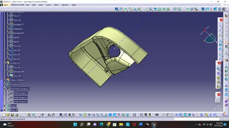
STEP 2:- CHECK FO BOUNDARY .
STEP6.
CREATION OF FINAL COMPONANT
triming class A,C with class B using trim command,
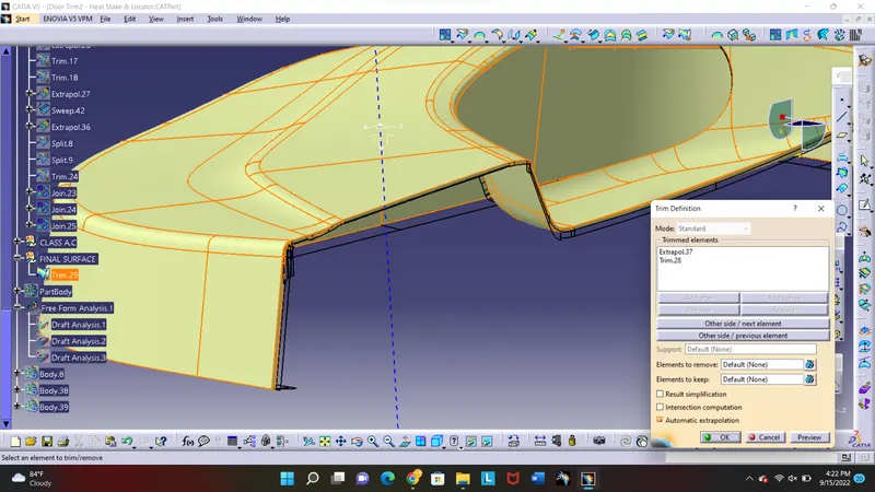
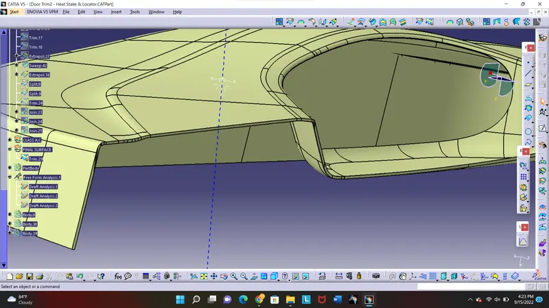
FINAL COMPONANT.
STEP7.
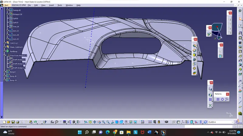
STEP 1:- CREATING FINAL SOLID COMPONANT USING CLOSED BODY METHOD.
STEP 2:-
DRAFT ANALYSIS OF FINAL COMPONANT,
3 degree of draft angle on bisecting tooling axsis shows some edge as negative draft as mentioned in class A draft analysis report ,result is as shown in below fig.
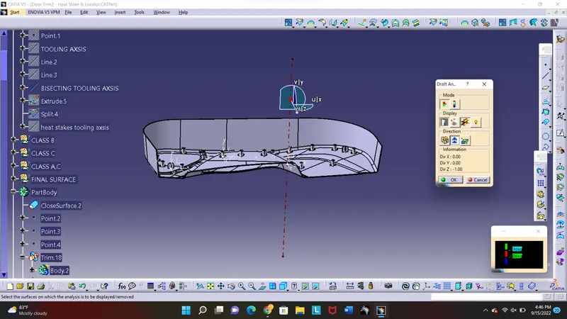
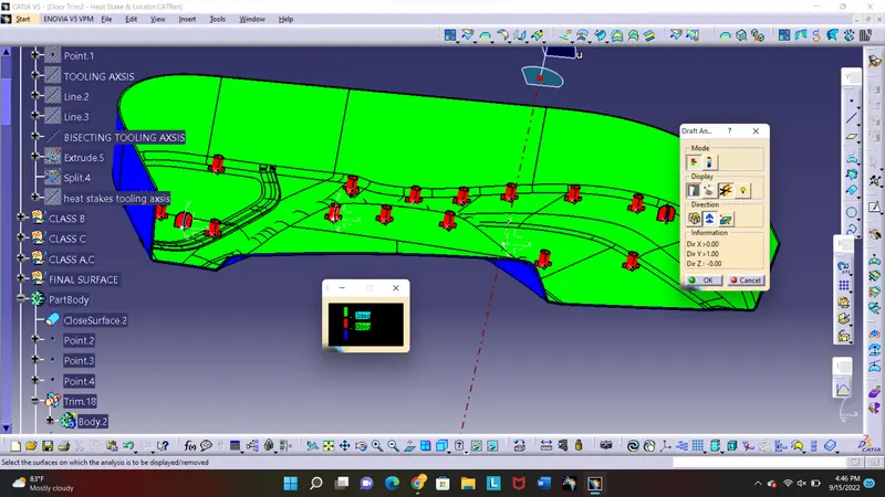
this edges shows negative angle with 3 degree .
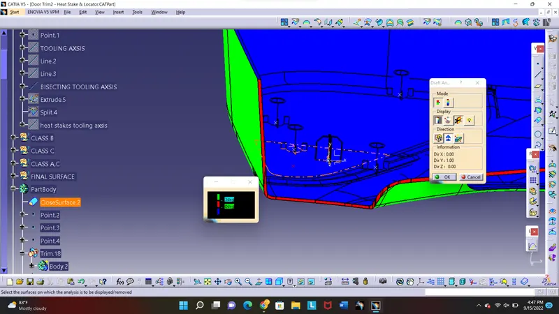
STEP 3:- check for different draft angle ,
in this componant draft cleared at 2.7 degree .
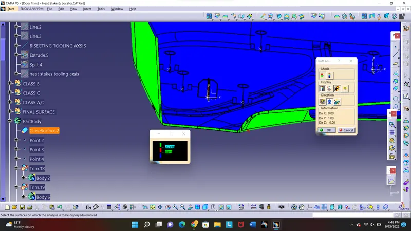
STEP 8.
CREATION OF HEAT STAKE
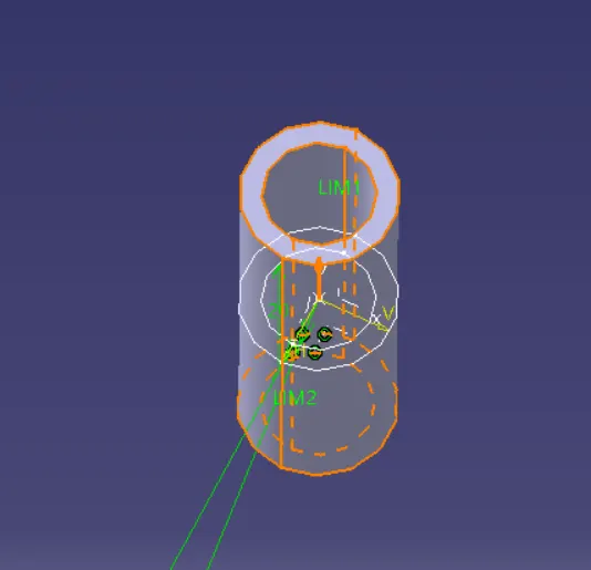
STEP 1:- take a point on surface and add axsis system to it .
STEP 2:- draw circlw of radius 5mm and 7mm and pad it.
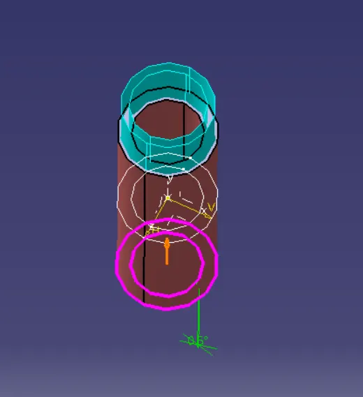
STEP 3:- give draft on inner and outer side of circle of 0.5 degree of angle.
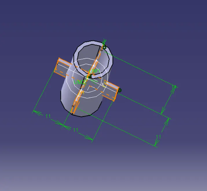
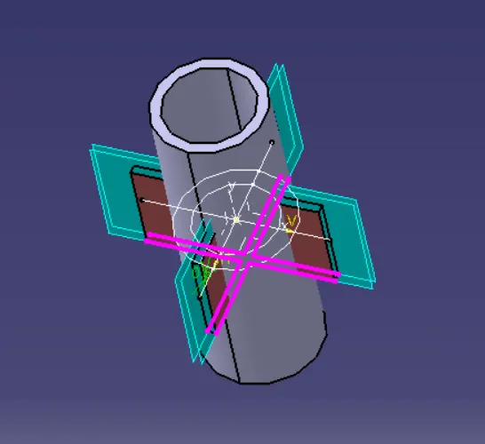
STEP 4:- draw a sketch of two lines of 22mm perpendicular to each other and then pad it with thickning it.
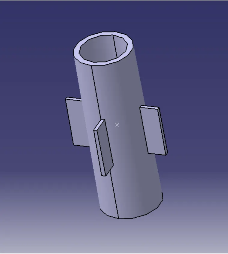
STEP 5:- give draft on all the surfaces of 0.5 degree of angle.
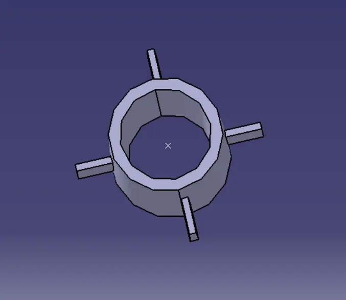
STEP 6:- union trim both bodys to make heat stake.
fig represents all steps explained.
STEP 9.
CREATING 2 WAY LOCATERS.
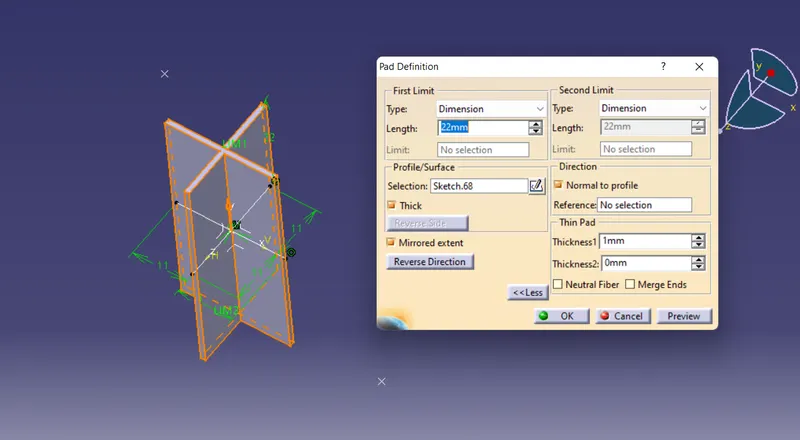
STEP 1:- draw a sketch of two lines of 22mm perpendicular to each other and then pad it with thickning it.
STEP 2:- total height of locator should be 1-2 mm more than heat stake.
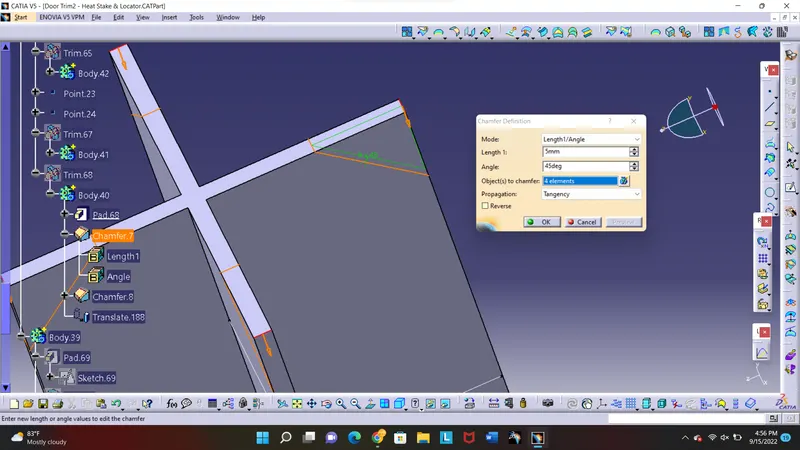
STEP 3:- give chamfer of 45 degree with 5mm.
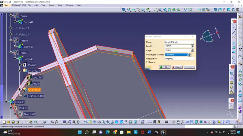
STEP 4:- give chamfer of 45 degree with 0.5mm to outer edges.
STEP 5:- provide draft with 0.5 degree to all faces.
given fig shows all steps explained.
STEP 10.
DRAFT ANALYSIS OF HEAT STAKE AND LOCATOR.
CREAT TOOLING AXSIS FOR HEAT STAKE AND LOCATOR .
STEP 1:- draw line on point where heat stake is created using point and direction.
STEP 2:- insert draft analysis , place compass on tooling axsis and define the direction, and again place compass on tooling axsis and click on surface, following fig explains the process.
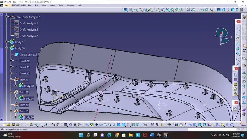
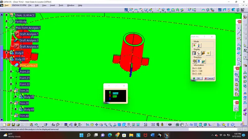
DRAFT RESULT WITH 0.5 DEGREE OF DRAFT ANGLE GIVES NEGATIVE DRAFT .
COMPONANT DOES NOT CLEARS DRAFT .
RED COLOUR SHOWS NEGATIVE DRAFT.
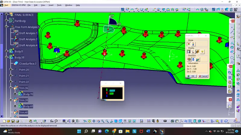
STEP 3:- try changing values .
by changing value from 0.5 to 0.4 the componant cleared the draft as shown in fig below.
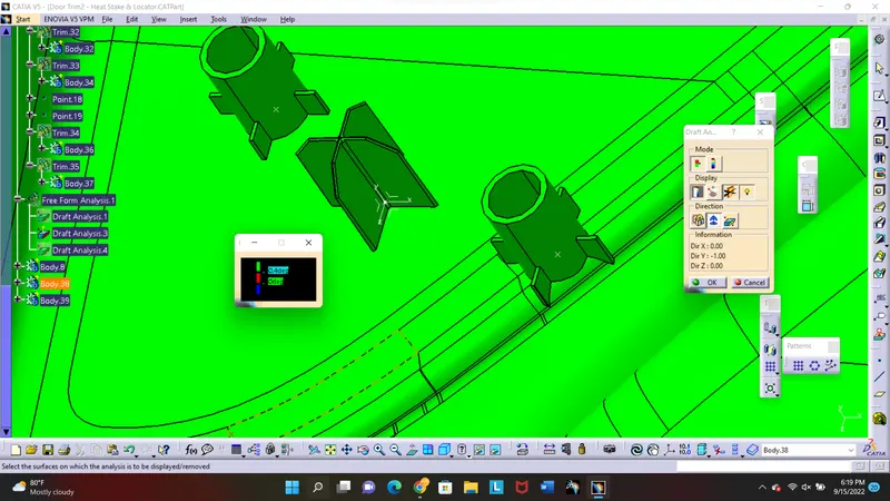
all heat steaks and locators shows green coloure which shows clearence of draft.
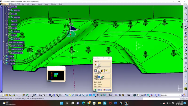
#conclusion:- componant clearing draft analysis can be manufacture.