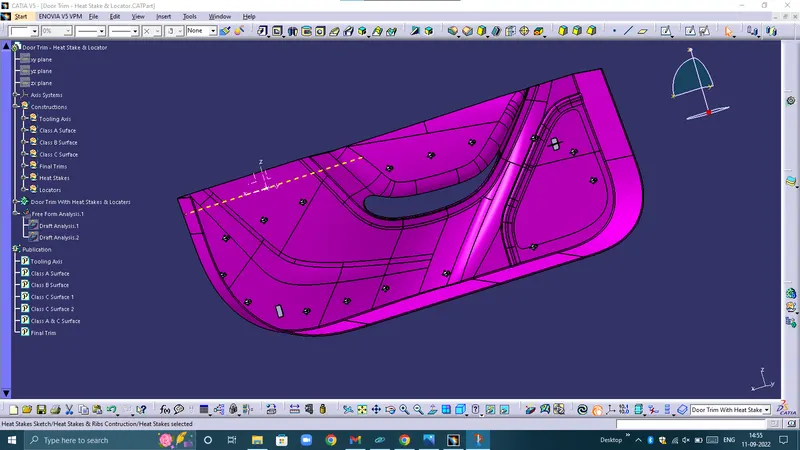
Week 9 - Project 1 - Door Trim Lower with Engineering Features
AIM: The Door Trim Plastic component through the given Class-A surface. To begin with, the tooling axis for the given Class-A Surface is created meeting the requirements of the draft angle and at the end perform the Draft analysis on the model.
A) Creation of the Plastic Component
Step 1: Tooling Axis
At first a point was created on the surface of the Class A, and a line Normal to the Surface is to created as the Tooling Axis.
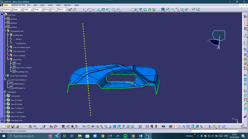
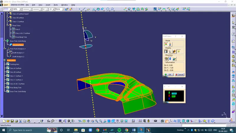
Step 2: Draft Analysis
The tooling axis created is checked for drafting by using Feature Draft Analysis tool. The created tooling axis was found to be correct for the the minimum draft angle of 3 DEG.
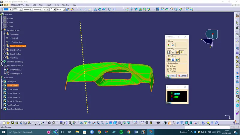
Step 3: Class B Surface
The Class B Surface was with an offset value of 2.5mm is to be created. At first the Class A Surface is offsetted and found to be errores.
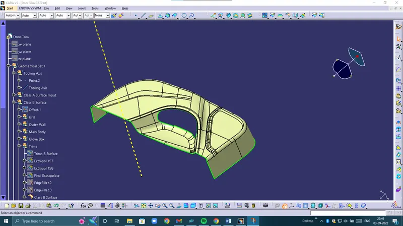
To simplify the model the surface was splited into 4 parts; namely the Main body part, the Glove box part, the Grill part and the Outer Wall. These parts are extrapolated to the ends and trimmed with each other and later on the radius is given to the joined edges using the edge fillet option.
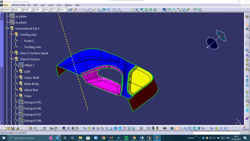
Class B Surface:
Step 4: Class C Surface
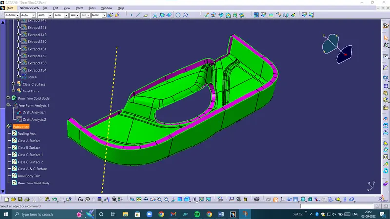
The Class C Surface is now then created with the boundary extracted from the Class A Surface, and then using Sweep tool the Class C Surface was created. The sweep was created at a draft angle of 3 DEGREE.
Step 5: Class A & C Surface
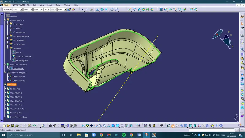
The Class A surface was joined with the Class C surface with the connexivity value of 0.003mm.
Step 6: Final Door Trim
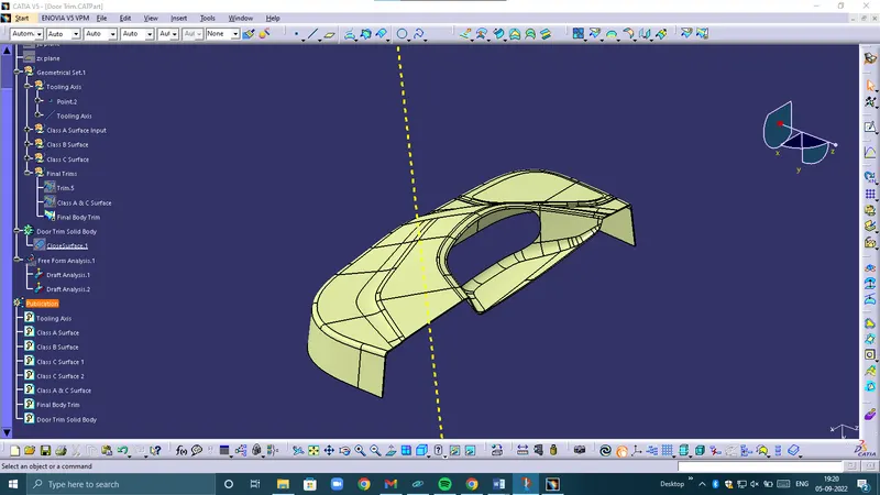
The joined Class A & C surface was then trimmed with the offsetted Class B Surface at 2.5mm.
Step 7: Final Plastic Door Trim
The trimmed component is closed using the close surface toolbar to foorm the solid plastic body.
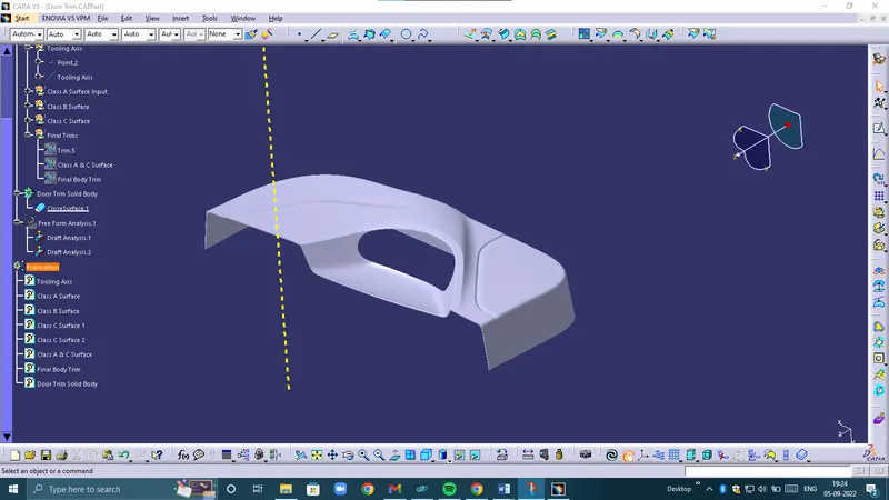
Step 8: Final Draft Analysis
The Draft analysis was done to the final closed body DOOR TRIM and was found to be correct with a minimum draft angle of 3 DEGREE.
CREATION OF LOCATORS:
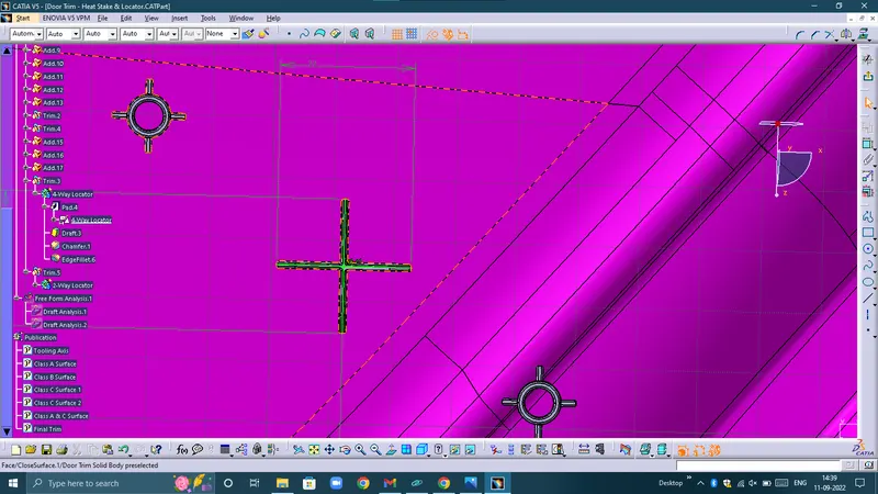
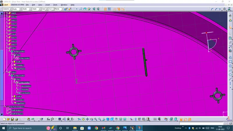
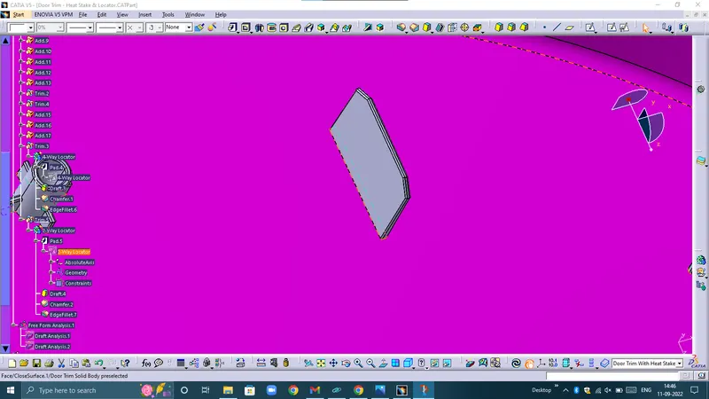
To create the locators, I created a sketch on the body. After creating the sketch, I pad it 20mm in height and thicken it to 1.3mm and I drafted it with 0.5deg in the direction of the tooling axis. I gave 3mm of chamfer with 45deg of inclination and after I gave a fillet of 0.3mm radius.
4-Way Locators:
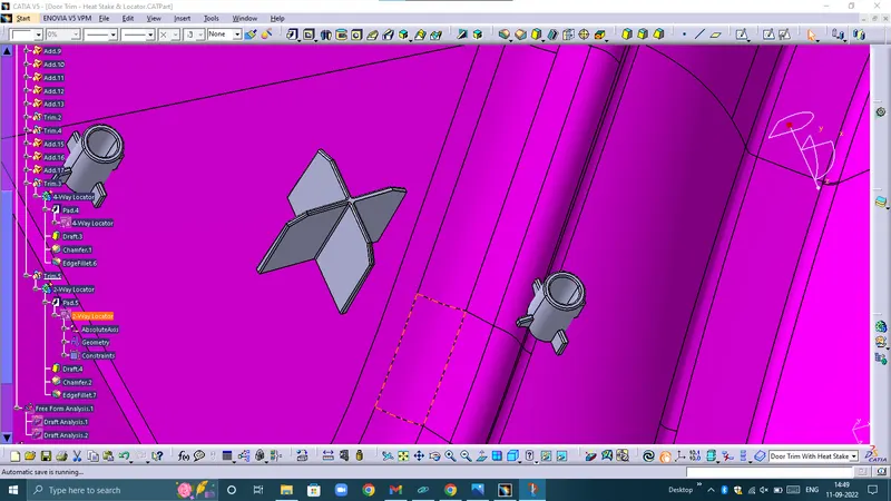
2-Way Locators:
CREATION OF HEAT STAKES:
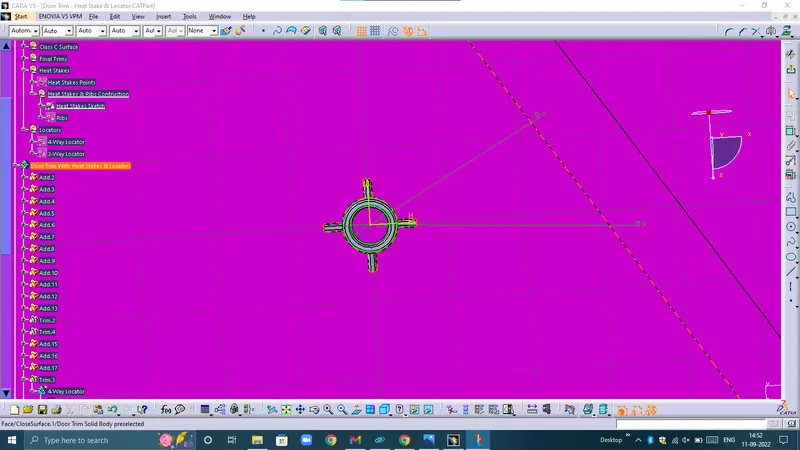
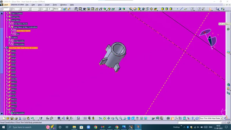
To create the heat stakes, I draw a sketch on the surface. After the creation of the sketch, I pad it to 15mm height and I gave a draft angle of 0.5deg on both sides (inside and outside) and then I gave a fillet with a 0.25mm radius. After creating the heat stake, I created the ribs for supporting purposes. To create the ribs, I draw a sketch and padded it to 6mm in height and 1mm in thickness. After padding the ribs, I drafted 0.5deg in the tooling asix direction and filleted it with a 0.25mm radius. Finally, I union trim the ribs with a heat stake to remove the ribs, which are present inside the heat stakes.
Heat stake sketch:
Final Body Door Trim with Heat Stakes & Locators: