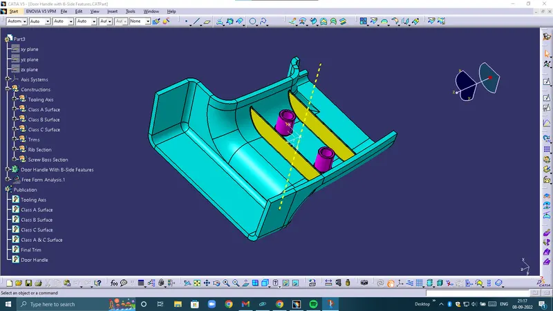
Week 9 - Attachment Feature Creation (Ribs & Screw Boss) - Challenge 1
Aim:
To create the rib for the Drill Handle considering the design rules in the door handle.
Design Rules:
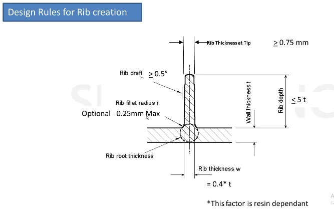
Design Rules for Rib creation:
Create the Screw boss for the Drill Handle considering the design rules mentioned in the video.
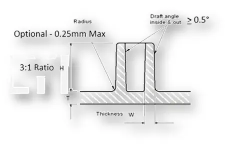
General Guidelines for Bosses:
- Draft - 0.5 degrees on the walls of boss
- Thickness - Typically 40%* of the nominal wall at the base.
- Height to Diameter Ratio - 3:1
- Radii - 0.25mm maximum radii.
Procedure:
A: Creating a Plastic Component of the Door Handle
Step 1: Tooling Axis
The Tooling Axis was created on the surface of the Class A Surface of the Door Handle. A point was created on the surface along the Y-Axis since it is the only possibility to create a mold for manfacturing. Then a line normal to the surface was created and draft analysis was done to check whether or not the tooling axis is correct and has a minimum value of 3 DEGREE.
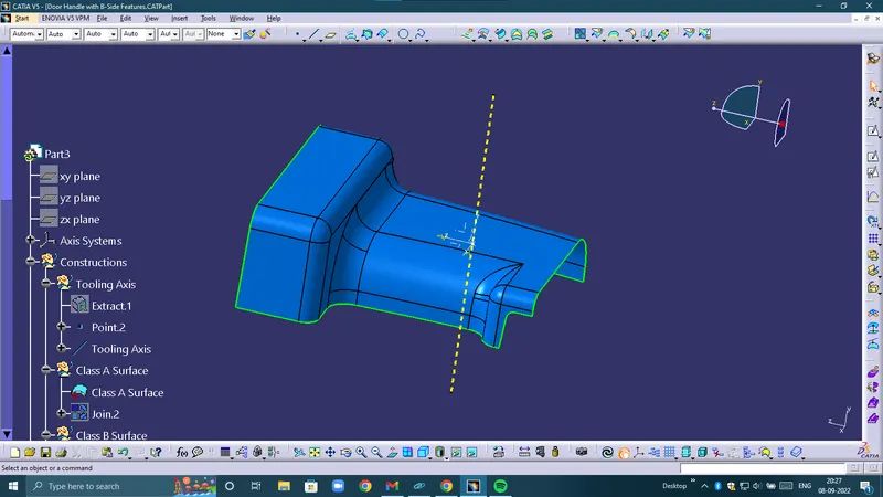
Step 2: Creating the Class B Surface
The Class A Surface is Offsetted to a distance of 2.5mm and the Class B Surface is created.
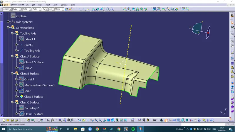
Step 3: Creating the Class C Surface
The Class C Surface is created by creating a boundary on the Class A Surface and by using the sweep tool it is sweeped to a nominal distance along the draft direction.
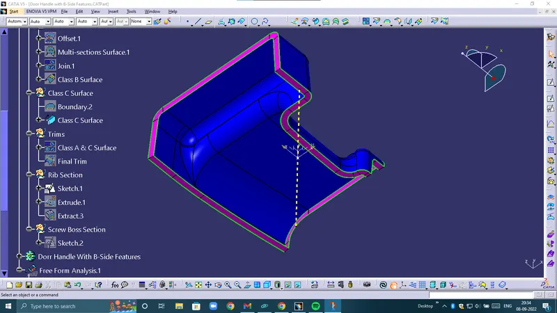
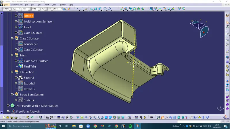
Step 4: Creating the Final Body of the Door Handle
The Class A & C Suface is first joined and then the joined surface is trimmed with the Class B Surface.
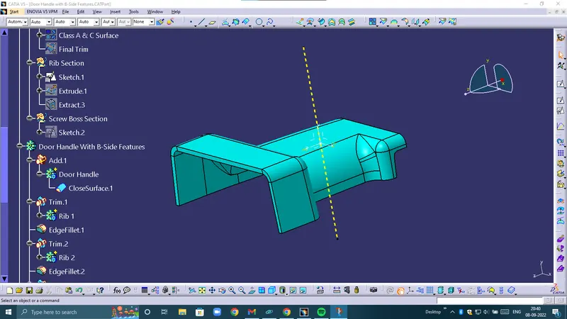
Step 5: Plastic Body of Door Handle
Using the Close surface tool in the part design workbench the plastic component is created.
B) Creating the B-Side Features of the Door Handle
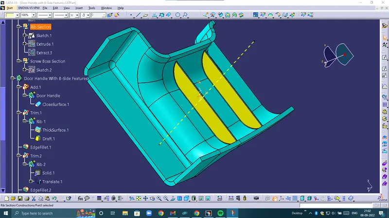
Step 1: Creating The Ribs
A sketch was created on the bide of the Door Handle comprising of a line. The Line was extruded and thickened using the thickness tool in Part Design Workbench. Then a draft angle of 0.5DEGREE was given to the Sides of the thickened part. Considering the design rules of the ribs:
- Extrude height = 5T
- Thickness = 0.4T
- Minimum Draft Angle = 0.5 Degree,
where T is the thickness of the component (i.e.T = 2.5mm)
The created thickened surface was then added to the solid body of the door handle using union trim option. Finally the fillets are given to the rib section.
Step 2: Creating the crew Bosses
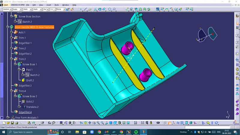
A sketch was created on the surface of the B-Side considering a M6 screw, by inserting a body the sketch was padded upto the height with a 3:1 ratio following the design rules and then drafted to minimum value of 0.5 Degrees on the walls.
- Draft - 0.5 degrees on the walls of boss
- Thickness - Typically 40%* of the nominal wall at the base.
- Height to Diameter Ratio - 3:1
The screw bosses were thenadded to the component using the union trim option. Finally after adding the fillets where given to the edges of the Screw Bosses following the design rules.
- Radii - 0.25mm maximum radii.
C) Final Body Draft Analysis
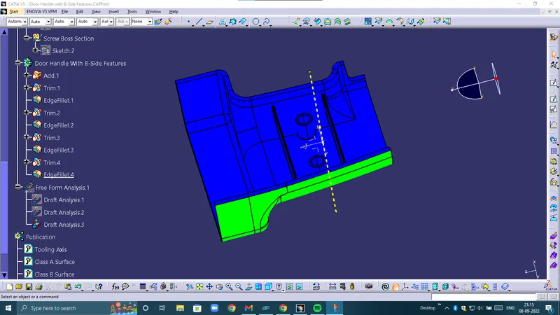
The final body was analysed at the tooling axis and found to be correct with minimum value of 3 DEGREE.
FINAL PLASTIC BODY OF DOOR HANDLE