Week 9 - Project 1 - Door Trim Lower with Engineering Features
DOOR TRIM LOWER WITH ENGINEERING FEATURES
OBJECTIVE:
The motive of this report is to illustrate the procedures involved in designing a solid model of Door Trim Lower using a class A surface as an input and perform draft analysis on this model.
INTRODUCTION:
In this report we are going to learn how a Class A surface as an input is utilised to create a solid model of Door Trim Lower according to OEM's standards. Here we will design class B and C surfaces from the given class A surface and joining them altogether to form a closed surface model and finally converting that closed surface into a solid part. Here we will also learn how to perform draft analysis of the model which is followed by mos of the OEMs.
DESIGN METHODOLOGY
- CREATION OF TOOLING AXIS
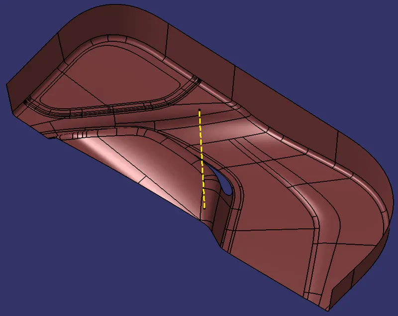
- The first thing to create the tooling axis is to analyse the class A surface through visual inspection.
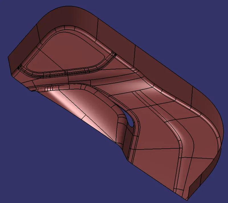
- When we see the class A surface in isometric view we can clearly see that it consists of basically two types of surfaces one is a nearly flat surface and the other one is forming a kind of pocket into the flat one.
- The flat surface is not going to create any problem during the tooling operation but the second one which is in a shape of a pocket can create problem during tooling.
- So to clear the pocket walls we will first extract and untrim the base surface of the pocket and then insert a point in the middle of the base surface, after that we will insert the axis system on that point.
- In order the to clear the side walls of the pocket we will intersect the YZ plane of the axis system with the class A surface with the help of intersect command. After that we will create lines along the side walls with the help of the obtained intersection curve.
- After drawing these two lines we will create another line which will bisect the earlier drawn two lines, we will use bisecting line option to create this line.
- To clear the front face or wall of the pocket we'll again use intersect command to intersect the ZX plane with class A surface, from here we'll get an intersection curve with the help of which we will create a line along the front wall of the pocket. we will create a line which be at an angle of 6 degrees to the previous line and passing through the point at middle of th base wall.
- Finally we'll create a final line which will bisect both tooling lines clearing X and Y directions and this line will be called as the main tooling line.
CLASS A SURFACE
- CREATION OF CLASS B SURFACE
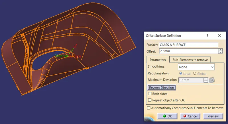
- To create the class be surface first we'll extract each and every surface of the class A surface except filleted surfaces.
- After extracting them individually we will untrim them to bring them back into their respective primary shapes.
- The untrimmed surfaces still don't intersect to each other completly so to intersect them completly we will extrapolate them with point continuity option.
- Then we'll give each and every surface with an offset value of 2.5mm (thickness of the model) in the downward direction.
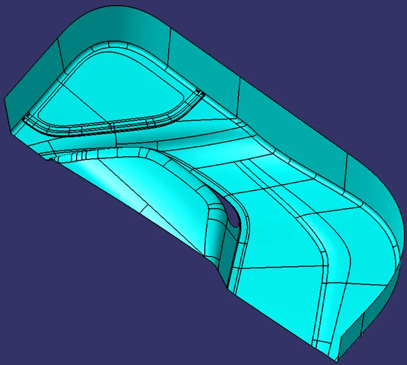
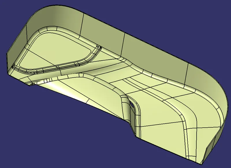
- Finally we'll trim all the surfaces one by one untill we join all the surfaces into a single entity After applying fillets(class A fillet radius - wall thickness) to the final trim, the resulting surface that we'll get will be called as the class B surface.
CLASS B SURFACE
- FORMATION OF CLASS C SURFACE
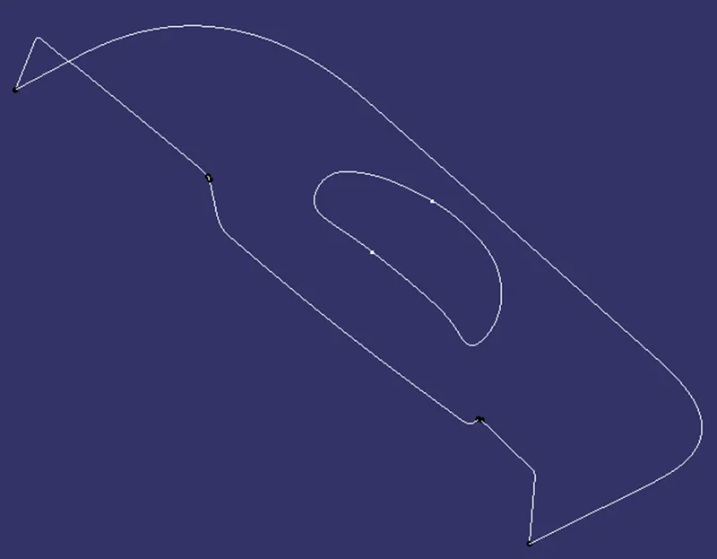
- To begin with C surface creation we'll first extract the boundaries of the class A surface for this we'll use mutiple extract and selecting tangency propogartion. From this we'll get two continous curves.
- Since these two curves contains a lot of patches so to remove these patches we will smothen the extracted curves by using smooth command.
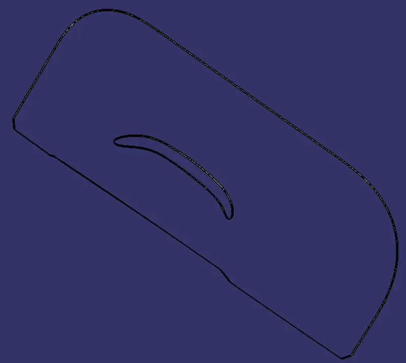
- Use sweep command and select "with draft direction" as the subtype, choose the smooth curves as the profile to sweep and choose the tooling axis as the draft direction.In addition to this give a draft angle of 3 degrees.
- Now extend the boundaries of the obtained sweeps using extrapolate command with boundary option.
- Finally trim both the sweeps with each other removing the extra part of the surfaces and joining them at the same time. The resulting surface we get is called the class C surface
CLASS C SURFACE
JOING OF SURFACE A AND C
- FORMATION OF CLOSED SURFACE
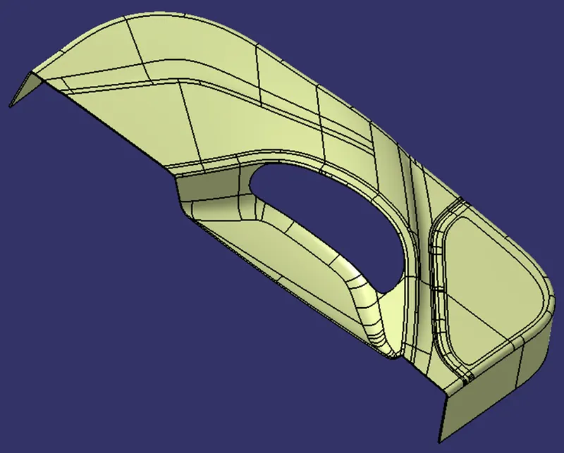
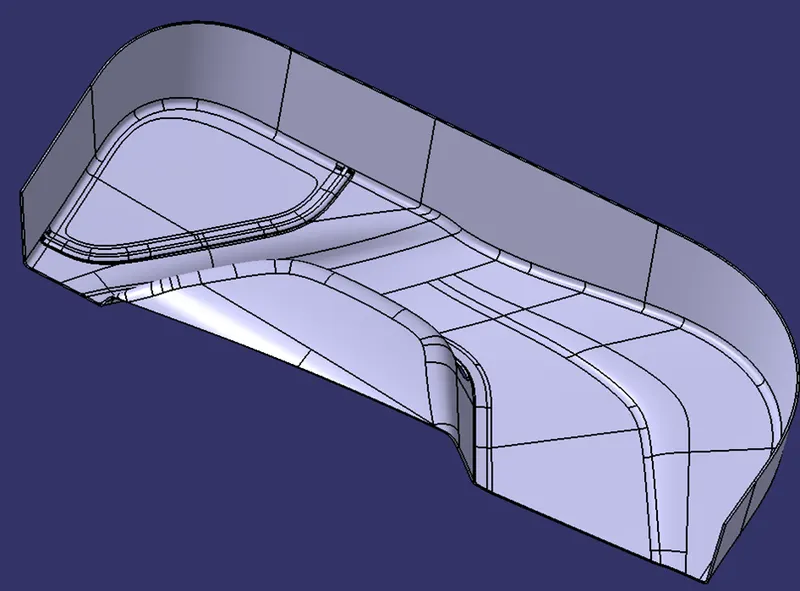
- In this part first we'll trim class A surface with class C surface and then finally trimming off the class B surface with the resulting trim of class A and class C surfaces. The resulting trim that we'll get from this final trim will be a shell or closed surfaced model of the Door Trim Lower.
- FORMATION OF SOLID PART MODEL OF DOOR TRIM LOWER
- After we get the closed surface model of the Door Trim Lower we'll go to part workbench of Catia V5 where we will use the closed surface command to convert the closed surface into a solid part and hence we’ll get solid model of Door Trim Lower.
DRAFT ANALYSIS
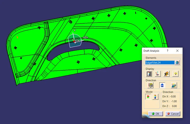
- Last but not the least , draft analysis is the process where we check whether the model is feasible for tooling operations in the moulding process. In draft analysis we have to make sure that all the surfaces of the model are well within the permissible draft limits.
- For initiating draft analysis go to tools> analysis> feature draft analysis we will find two dialog boxs for doing the anlaysis.
- In the big dialog box click on the compass icon and then zooming in we find a compass somewhere in the screen, just pan this compass along the tooling axis and make sure that the axis of the compass and the tooling axis coincides with each other. Then click on the lock icon and if we don't want to light effect of the colours we can click on the light effect icon. The second dialog box is basically a colour scale which can be enabled or disabled through colour scale icon.
- This box basically shows three colours where the green one shows the surfaces having draft more than or equal to the permissible draft angle i.e 3 degrees the blue one shows the angle between 0 to 3 degrees anf the surface with red colour shows the angle less than 0 degrees.
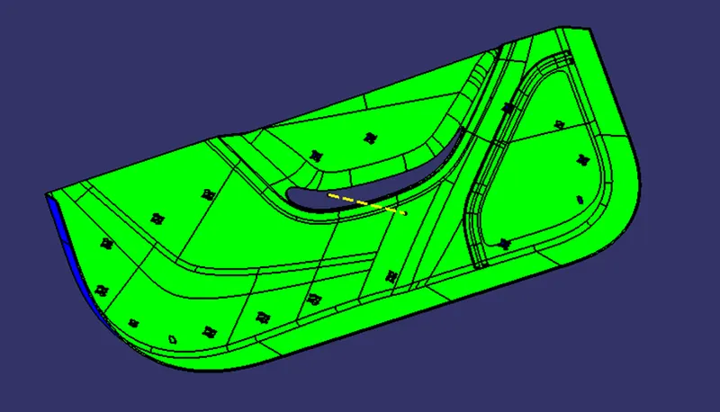
- In Draft analysis our task will be to work on the surfaces with blue colour which are having draft angles less than the permissible values and greater than zero. we can correct these surfaces by making corrections in the tooling axis or we can can reduce the permissible value of draft angles by a very small value to accomodate all the surfaces under the permissible value.
- When we reach to a point where the class A and C surface appears green in colour, it means our model is now feasible for tooling operation after the moulding process.
Creation of Heat Stakes
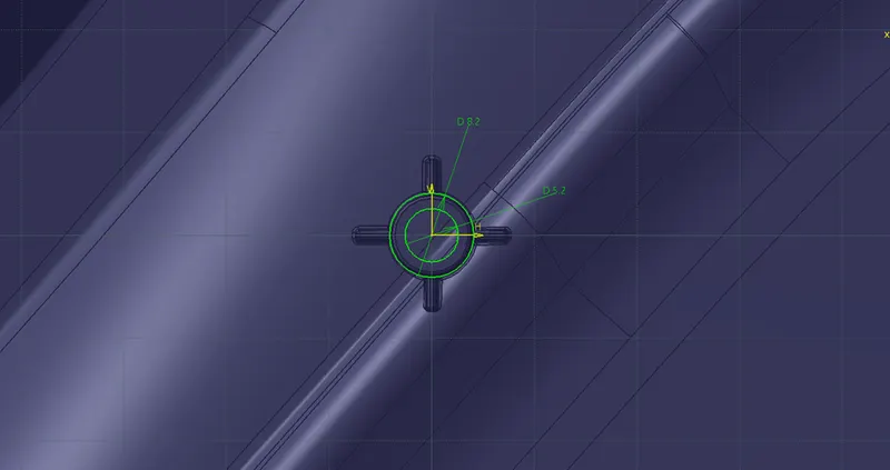
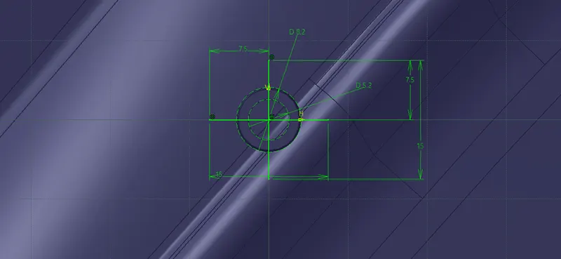
- To create the heat stakes, I sketch on the surface. After the creation of the sketch, I padded it to 18mm height and I gave a draft angle of 0.5deg on both sides (inside and outside) and then I gave a fillet with a 0.25mm radius. After creating the heat stake, I created the ribs for supporting purposes. To create the ribs, I draw a sketch and padded it to 6mm in height and 1.3mm in thickness.
- After padding the ribs, I drafted 0.5deg in the tooling axis direction and filleted it with a 0.25mm radius. Iso- Constrained Sketches.
- Now I translated the heat stakes by copy-pasting them in the part body according to the requirement.
Creation of 2-way and 4-way Locators
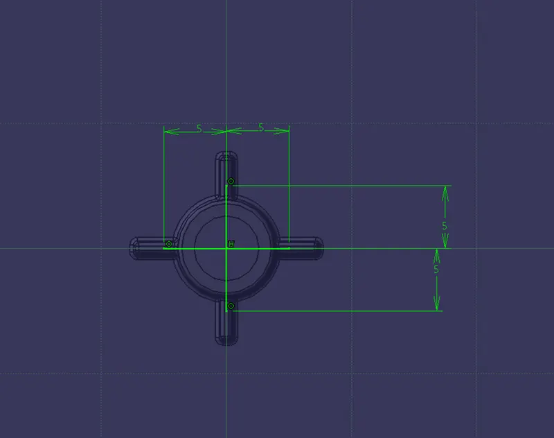
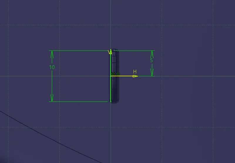
- To create the locators, I created a sketch of the body. After creating the sketch, I padded it 19mm in height and thicken it to 1.3mm and I drafted it with 0.5deg in the direction of the tooling axis.
- I gave 3mm of chamfer with 45deg of inclination and after I gave a fillet of 0.25mm radius. Iso-Constrained Sketches
4 way Locator
2 way locator
RESULTS
FEATURE TREE 1
FEATURE TREE 2
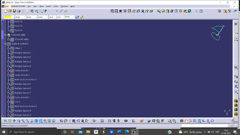
FEATURE TREE 3
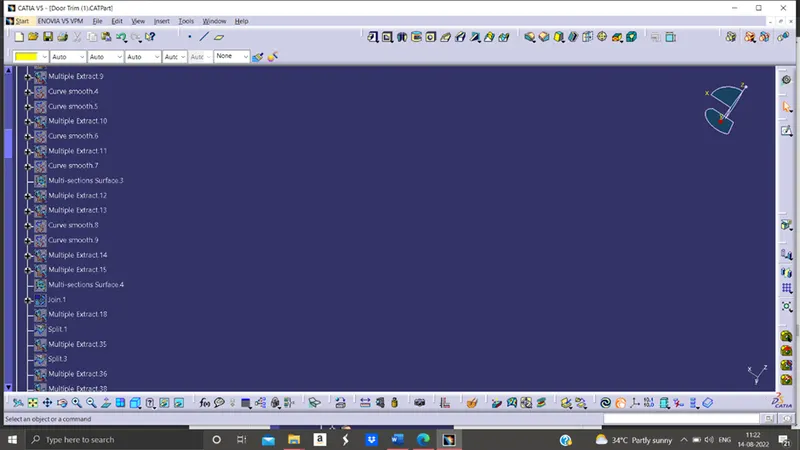
FEATURE TREE 4
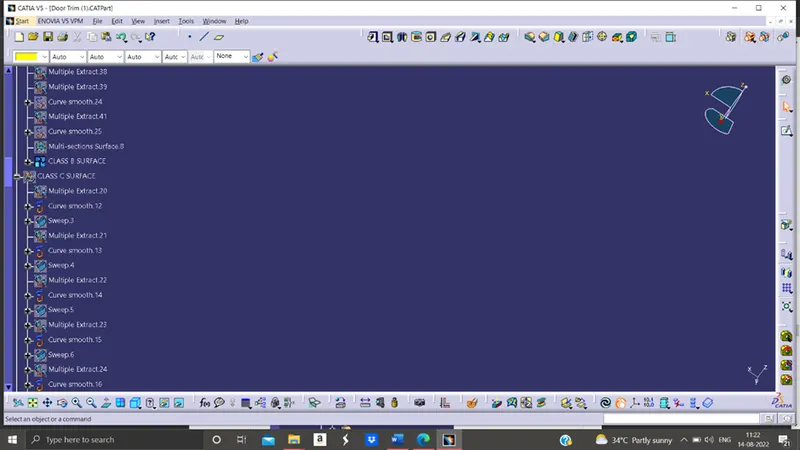
FEATURE TREE 5
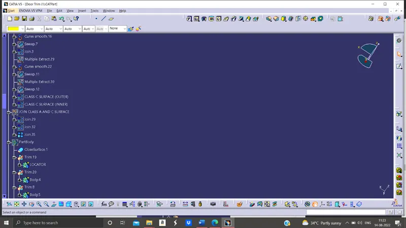
FEATURE TREE 6
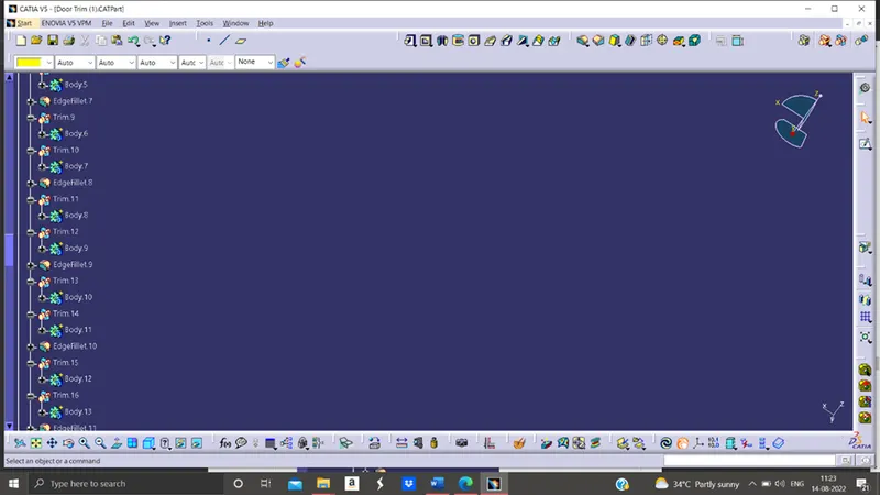
FEATURE TREE 7
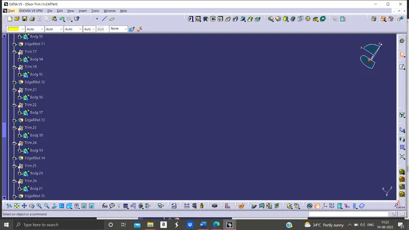
FEATURE TREE 8
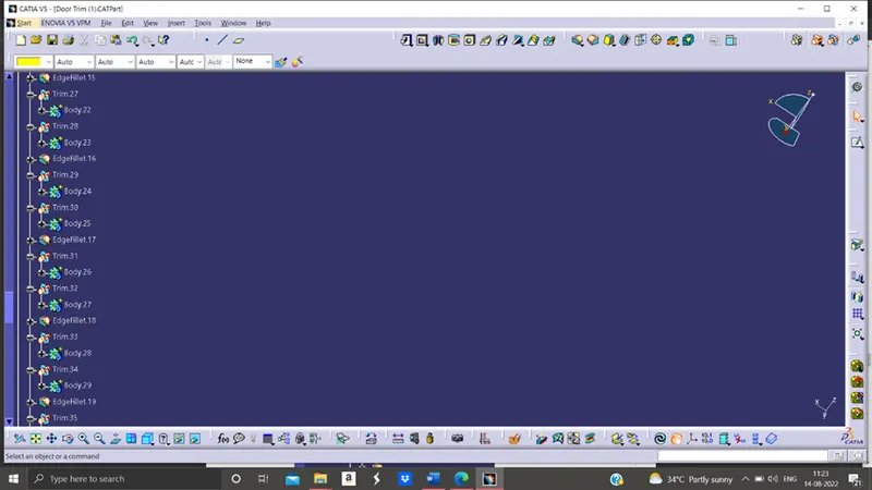
FEATURE TREE 9
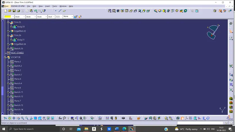
FEATURE TREE 10
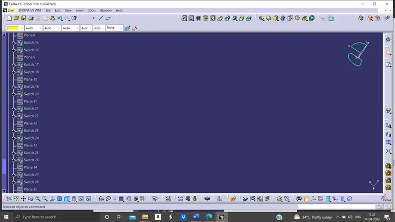
FEATURE TREE 11
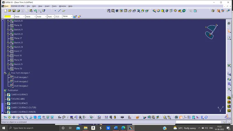
FRONT VIEW
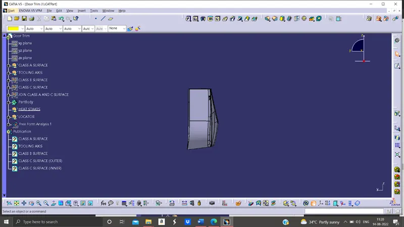
TOP VIEW
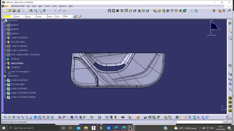
BOTTOM VIEW
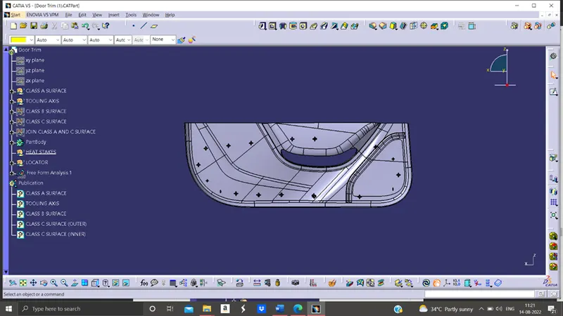
ISOMETRIC VIEW
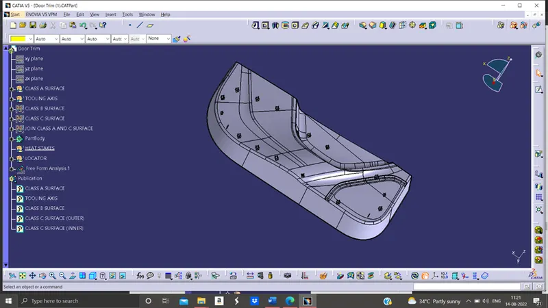
CONCLUSION
· Created the Door Trim Plastic component through the given Class-A surface, the tooling axis for the given Class-A Surface and meeting the draft angle requirements and performed the draft analysis on the model at the end.
· And also created the Heat Stakes and the locators considering the design rules mentioned in the video for the door applique.