Week 9 - Project 1 - Door Applique Design with Engineering Features
Door Applique Design with Engineering Features
aim:
- Sketches
- Use Positioned sketch
- Sketches should be Iso-Constrained
- Tree Structure
- Ensure Proper Tree Structure
- Geometrical sets should have a proper name based on the sketches present inside of it
- All the sketches should be created under the Geometrical set
- Report
- A detailed report should be done explaining the draft analysis and the tooling axis creation.
- An explanation should be given on the way of creating the tooling axis particularly the Bisecting method.
requirements:
- CATIA-V5R21 software
procedure:
- intially we create a tooling axis creation by using point on a surface ( CLASS A SURFACE)
- then we choose locators position on a applique face side, it means which side we want that to be selected.
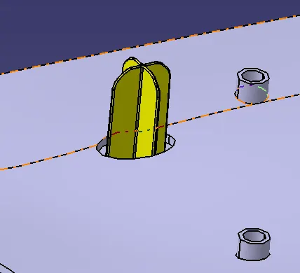
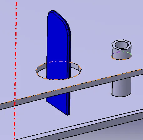
i. 2 way locators.
ii. 4 way locators
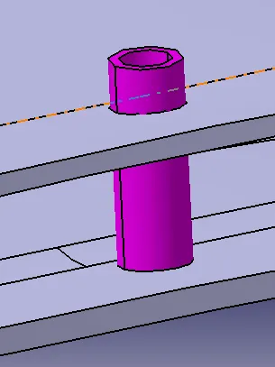
iii. heat stakes.
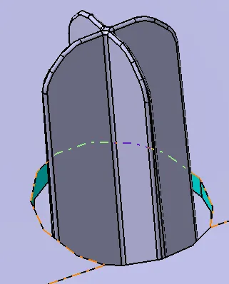
- so we creating clearance on a applique surface. the 4 and 2 way locators gap between is 0.1mm and heat stakes gap clearance is 0.05mm.
- finally to creating a feature draft analysis both Class A surface and Door applique design.
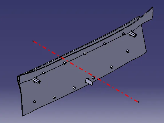
here some screen shots or photos.
isometric view:
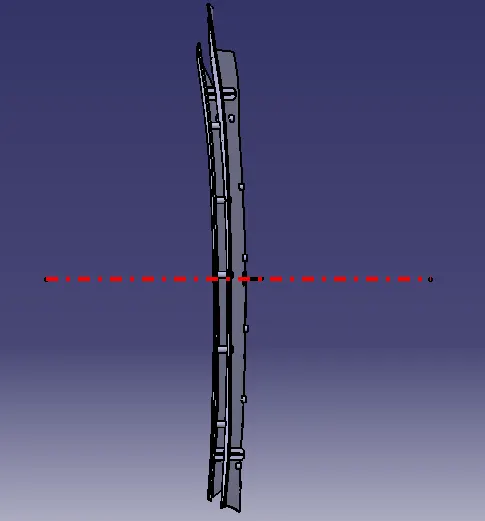
top view:
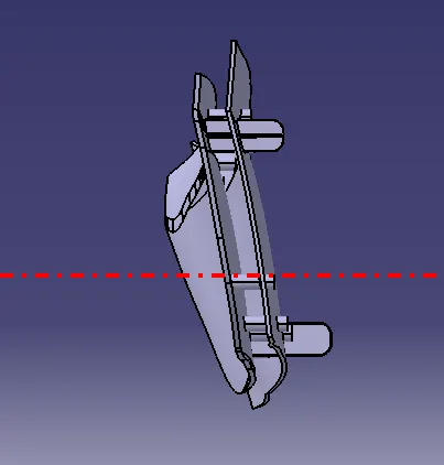
front view:
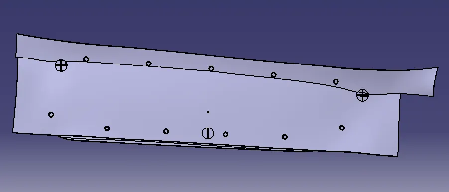
side view:
4 way locatots:
2 way locator:
heat stakes:
clearance 4 way and 2 way locators:
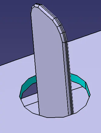
heat stakes clearance:
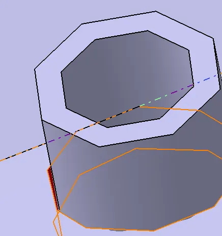
result:
door applique design is created by above following instructions...