Week 9 - Project 1 - Door Applique Design with Engineering Features
AIM: To Create the Door Applique Plastic component through the given Class-A surface. To begin with, the tooling axis for the given Class-A Surface was created meeting the requirements of the draft angle and performed the Draft analysis on the model and to Create the Heat Stakes and the locators considering the design rules as mentioned in the video for the door applique.
Draft:
Draft is an angular tapering given at the design stage to every Plastic Component that has to be manufactured. It is given in the direction of the Mold Movement. The Draft allows the parts to release easily from the mold without creating friction between the surface of component and the core and cavity plates.
When a Plastic component cools down inside the mold, the natural tendency of it is to shrink and attach to the core or cavity half. The movement of mold opening causes friction on the walls of the component as well as the core/cavity blocks. This reduces the life of the mold as well as the component itself. The component may also have rough surface finish as well as weak structure due to this. This problem can be solved by giving draft to the component.
Most applications require minimum draft angles of around 0.5° to 1°, however 3° draft angles are widely accepted for cost saving purpose. 7° Draft angles are given to textured surfaces like Instrument Panels. Minimum possible draft angles are given to screw bosses ribs and stiffeners due to their critical nature.
Draft Analysis:
The Draft Analysis command enables you to detect if the part you drafted will be easily removed from the mould. This type of analysis is performed based on color ranges identifying zones on the analyzed element where the deviation from the draft direction at any point, corresponds to specified values of angles along a defined draft direction using colour codes. It highlights the regions of draft using colours. . Draft analysis is the first step performed after receiving the Class A of the component.
Tooling Axis:
The direction in which the mold or core and cavity opens is the tooling axis. Part Drafts are designed along this axis.
Class-A Surface:
In automotive design, a class A surface is any of a set of free form surfaces of high efficiency and quality. It is the visible aesthetic surface of any automotive component.
Create tooling axis:
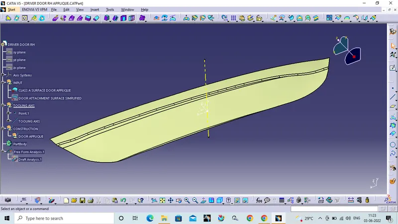
The given class A surface is a Flat surface in this case the tooling axis will be normal to yhe surface.
To create thye tooling axis create a point on the surface and create the line using the point and surface name it as tooling axis.
Draft analysis for class A surface:
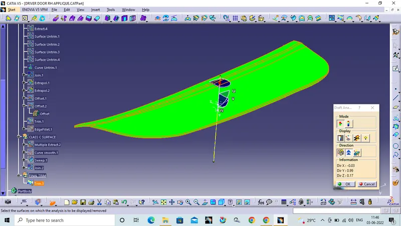
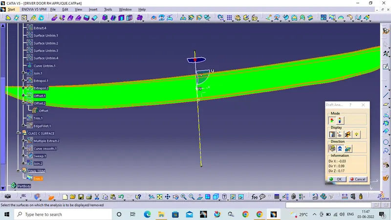
Go to insert - analysis click on Featured draft analysis and perform draft analysis.
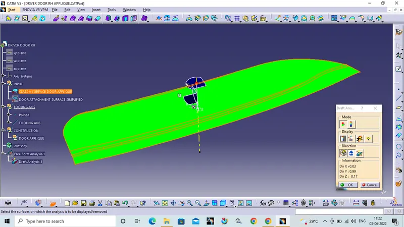
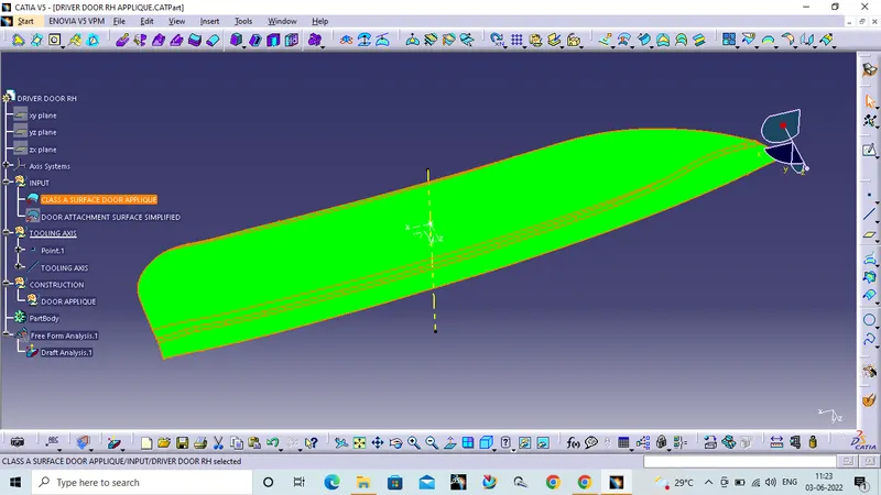
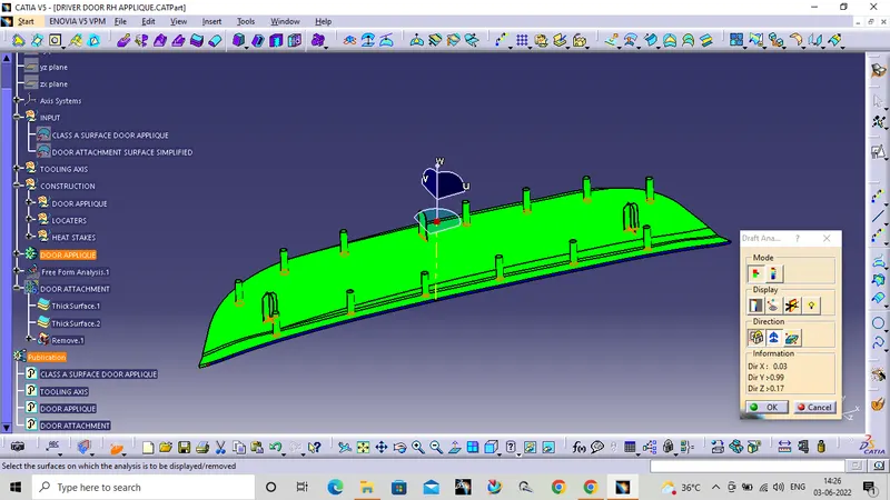
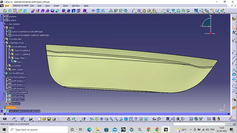
Green colour indicates the surface has draft angle of 3 degrees.
Creation of class B surface:
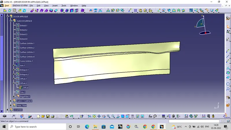
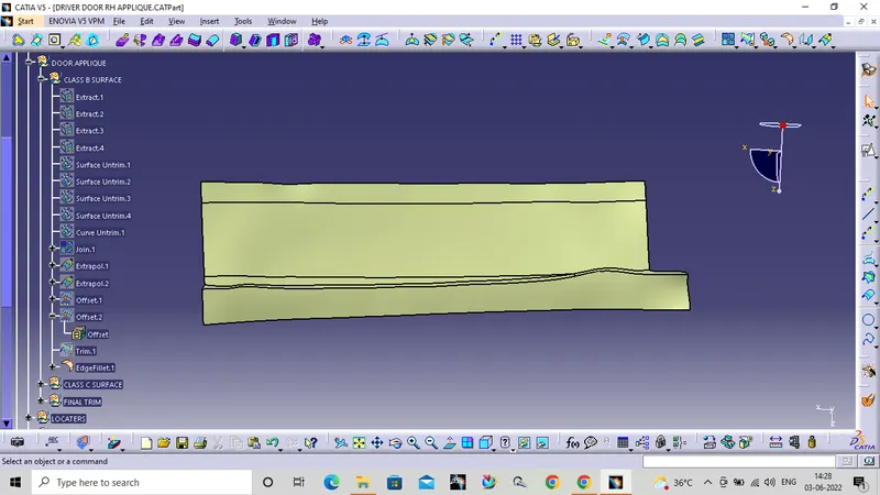
To create the class B surface first extract the face of the class A surfaces and untrim the faces for extrapolation and trim them, Offset the trim surface we get class B surface.
Creation of class C surface:
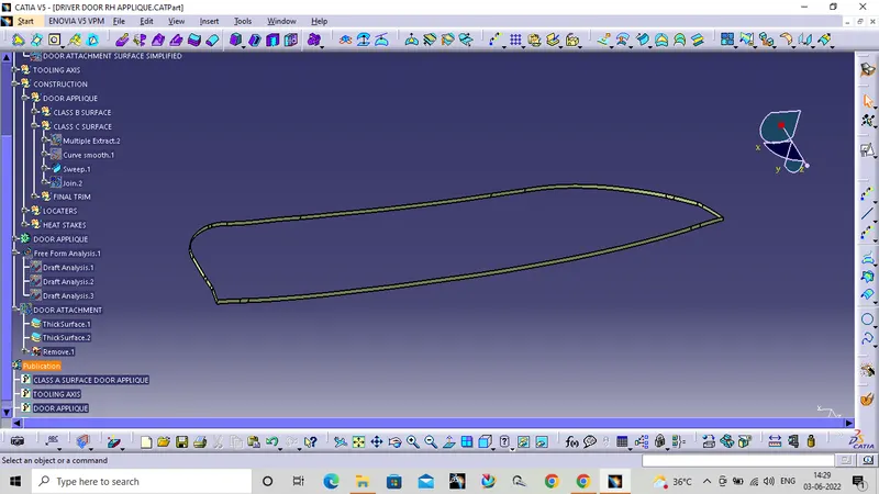
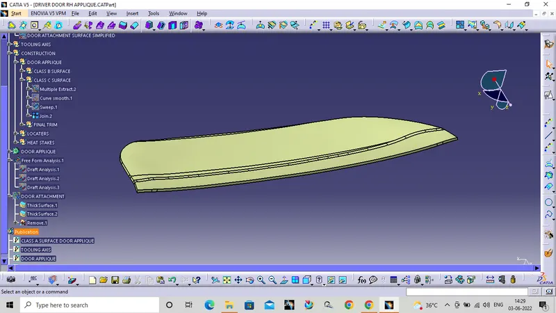
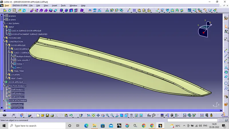
To create class C surface extract the boundary of the class A surface and create the sweep with tooling axis at 3 degree angle then join the Class C surface with Class A surface.
To get the final component Trim A,C and B surfaces.
Four and two way locators and heat stakes :
3-2-1 PRINCIPLE
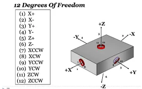
A work-piece free in space can move in an infinite number of directions. For analysis, this motion can be broken down into 12 directional movements or "degrees of freedom". All 12 degrees of freedom must be restricted to ensure proper referencing of a work-piece.
As shown in Fig 1, the 12 degrees of freedom all relate to the central axis of the work-piece. Notice the 6 axial degrees and 6 radial degrees of freedom. The axial degrees of freedom permit straight-line movement in both directions along the 3-principle axis shown as X, Y & Z. The radial degrees of freedom permit rotational movement, in both clockwise & counter clockwise radial directions around the same three axes.
Degrees of Freedom of a Rigid Body
Consider the rigid body shown below which is situated in space. It can have 12 degrees of freedom.
2-WAY LOCATORS:
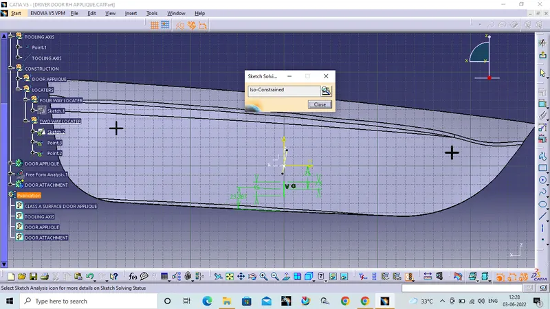
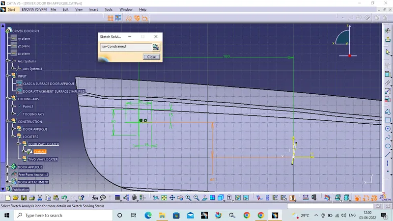
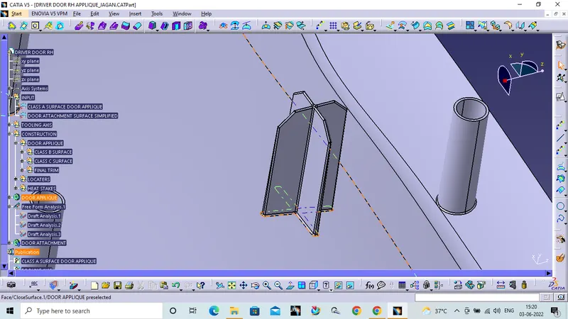
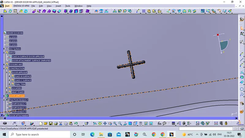
2-way locating pin restricts motion along axis (or 2 degrees of Freedom), like a round pin in a slot. where as in 4 way pin restricts 4 degrees of freedom along 2 axes.
4-WAY LOCATORS:
4-way we restricts movement in 2 axis (+X, -X, +Y and -Y) on the plane.
HEAT STAKES:
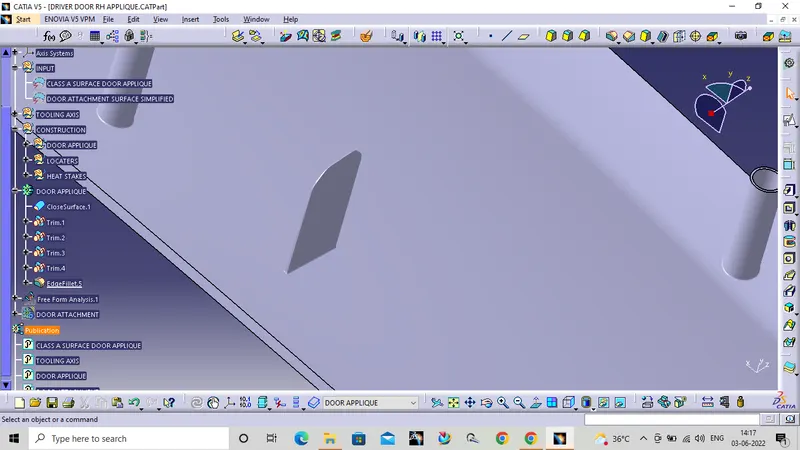
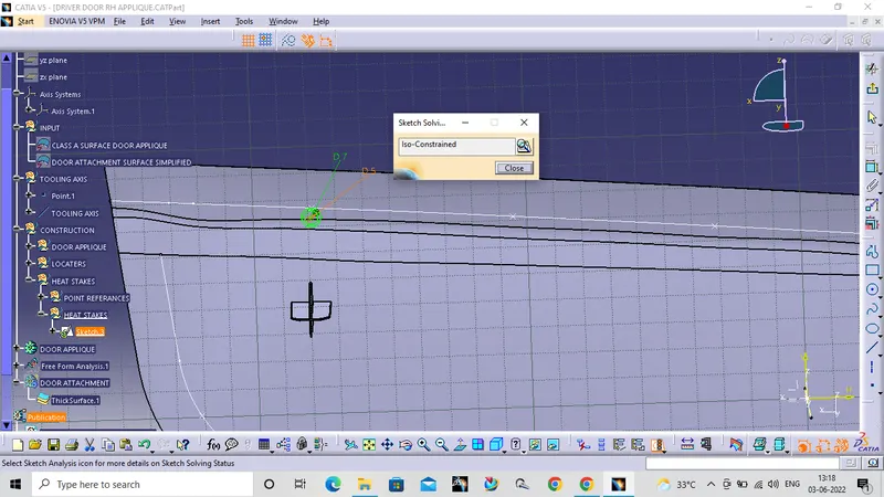
In manufacturing operations currently use many different combinations of attachment methods to keep components together. Common fasteners such as bolts, screws, and rivets can be used to form permanent attachments, but there are attachment methods that don't require secondary hardware. One of those methods is heat staking, which doesn't require additional fasteners.
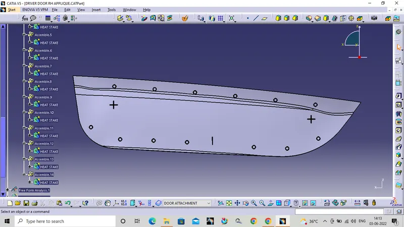
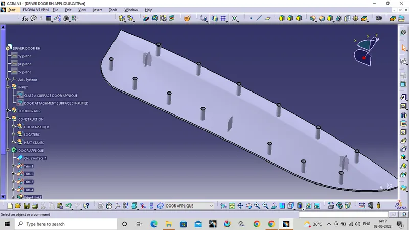
WHAT IS HEAT STAKING?
Heat staking is the process to attach two separate components together by melting the base plastic material into a shape that will hold the secondary component. It's a permanent attachment method that does not require any additional material such as an adhesive or a solvent to make the permanent bond. The only addition is the heat applied to melt the plastic and a tool to shape the plastic to form the mechanical connection.
Heat staking can be done with a precise and rapid operation that also offers repeatable results every cycle. Manufacturing machine can be developed to complete multiple heat staking operations at once to decrease cycle time. The stakes don't have to be parallel which makes the design options limitless.
Heat staking is a great option that is comparable in strength and durability to other operations involving secondary fasteners without extra cost. These connections can also resist corrosion in harsh environments.
REASONS FOR HEAT STAKING:
Combustion CFD Specialist
1.Mutiple staking shapes for different benefits.
2.Excellent durability.
3.No extra materials are needed.
4.Increased efficiency
5.Easy Maintenance.
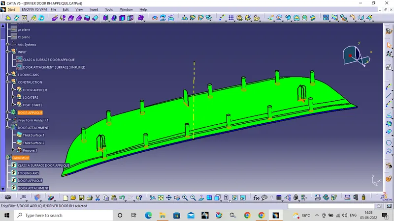
Draft analysis for the door applique :