Advanced Sheet Metal Design Using NX Cad Challenge_2_Box Assembly
TITLE : Sheet metal box assembly
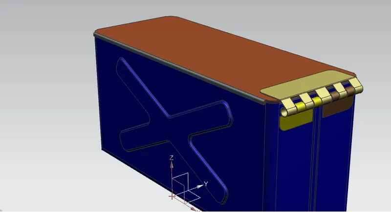
Obtective : To design a Box assembly using NX cad sheet metal workbench.
Intoduction :
sheet metal is a metal forming process used in industries to process thin,flat picess in to products.
Here i have created a sheet metal Box assembly of various thickend parts .
Box assembly contains 3 parts
- BOX(base part)
- BOX LID
- HINGES
To design this parts in nx sheet metal workbench. I have used this methodology described below.
Design Methodology :
Description :
Step by step of creating cad model of Box assembly descriped here.
Tools used to design Cad model is here
Box assembly has 3 parts
- Box
- Box lid
- Hinges
1) Box
1.Sketch
cerate a 2d sketch in xy plane of 200mm x 150mm rectangle
2.Tab
base of box by selecting the 2d curve from sketch create a tab of 1mm thickness
3.Side Flanges
side wall are created by selecting the edges of tab using flange feature
4. closed corner
this feature is used to porvide smooth corners by removing intersections and fineshed edges of flanges
5. hem flange
in hem flange use close loop feature to close the gap between the ends of the side flanges
6. Mirror body
using mirror body feature complet the box body.
7.Unite
after mirroring the the body use unite feature to unite 2 saperate bodies
8. Dimple
emboss is created on the body of box to give additional strength to the box using dimple feature.
9.Mirror feature
To create emboss on the other side of the box by using mirror feature tool by selecting the emboss created before on the other side of box
10. Dimple
Again using dimple feature created a dimple at the bottom of the box by sketching a rectangle on bottom face of box
11. bead
A bead is created at the bottom of box by creating a circle
12. mirror feature
Again using mirror feature 4 beads are created at the bottom of the box
13. hem flange
By selecting the top ends of box hem flange is created to give clean and smooth edges
2) Box lid
1) Datum plane
a datum plane created w.r.t xy plane at an distance of 203mm
2) Sketch
by selecting new datum plane created at the top of box create a sketch using top of the box edge references for box lid
3) Tab
using tab feature box lid is created
4) flange
flange is added at the edge of lid to complete the box lid
3) Hinges
here hinges are in 2 parts
1. box part
2. box lid part
1) tab
selecting the side face of box a tab is created on side wall of the box
2) Break corner
corner is blended with 10mm radius
3) 2 additional flanges create on the base tab
4) Hem flange
open loop hem flange is created
5) unbend,normal cut,rebend
flattened hinge portion to perform normal cut and rebend to get hinge in its original position
6) mirror body
using mirror body feature hinge part is completed on box
2) Box lid part
1) Tab
a rectangular tab is created on the to edge of the lid using tab tool of 2mm thickness
2) break corner
corners are blended with 10mm radius
3) Flange
a flange is added at the tab end using flange tool
4) Hem flamge
open loop hem flange is created
5) unbend,normal cut,rebend
same process is followed while creating box part hinge to create lid part hinges
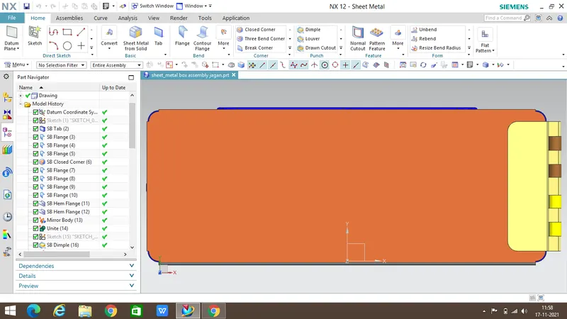
top view
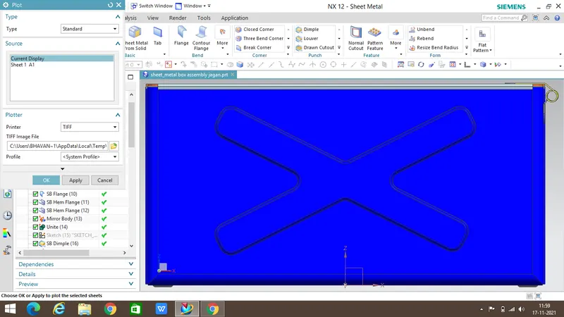
front view
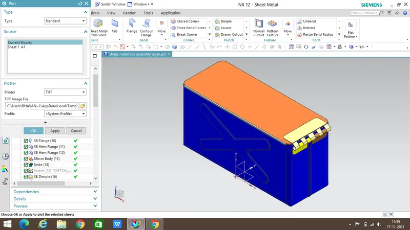
isometric view
side view
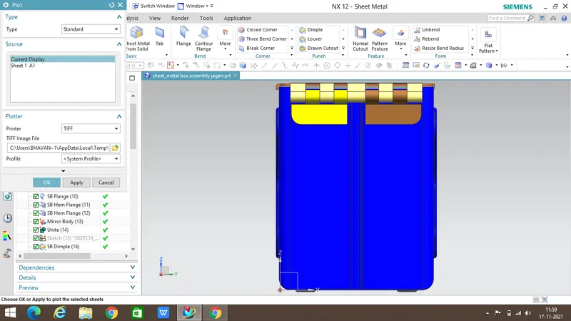
bottom view
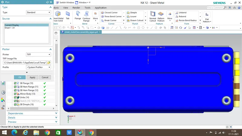
Conclusion :
by doing this project i have learned some new NX cad sheet metal tools like hem flamge, closed corners.