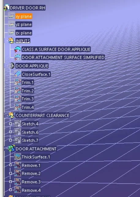
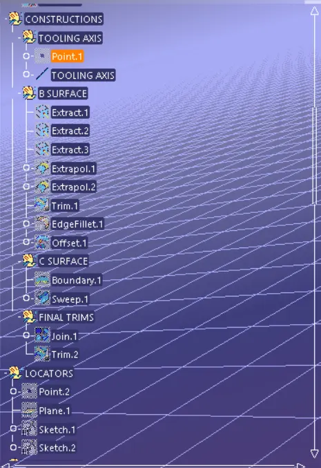
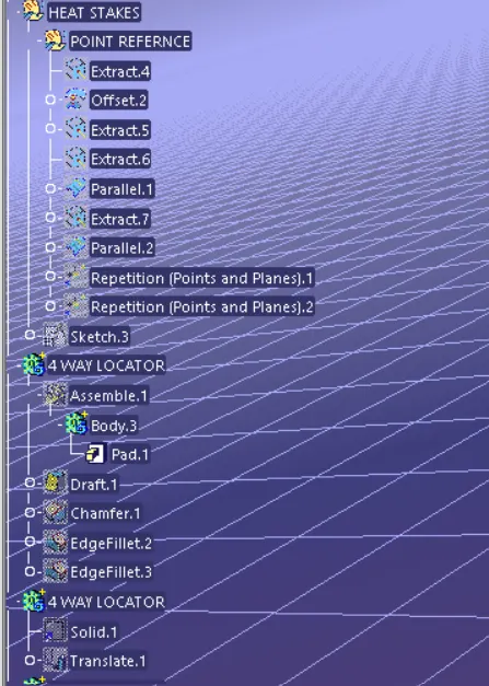
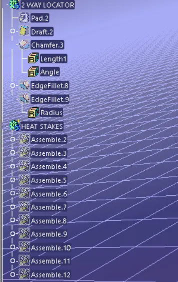
Week 9 - Project 1 - Door Applique Design with Engineering Features
Aim:
To create a door applique and door attachment from the given Class-A surfaces and to create engineering Features to fit the component in the main surface.
Introduction:
Engineering features are the extensions on the plastic components available on the class-B surface such as ribs, Screw bosses, heat stakes, locaters and Dog Houses etc., which help fix the plastic component to the main surface and to avoid plastic defects while manufacturing the component through mould process.
The features such as locators and heat stakes are to be assembled on the component(B- surface) shown below.
Procedure:
- Check the component for any kind of surface openings such and fix them if any.
- Create a tooling axis for the class A surface following the steps mentioned below.
(i) Create a point in the middle of the component.
(ii) Create a line perpendicular to the surface setting the created point as a base.
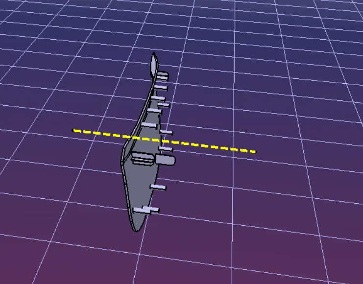
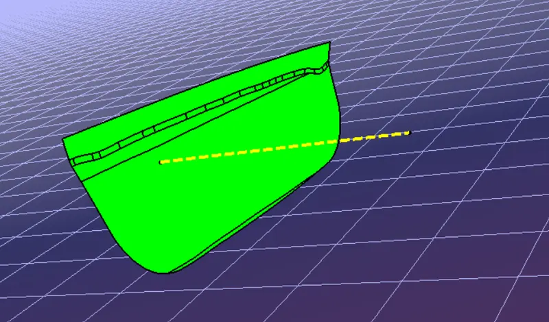
The obtained line is said to be the the TOOLING AXIS. To say whether the obtained tooling axis is correct, view the normal view of the line and make sure the whole surface is seen clearly.
- Create a class B and C surface for the component following the steps mentioned below.
4.Class B surface:
(i) Extract the plane surfaces from the class A surface neglecting the fillet surfaces.
(ii) Untrim the surfaces from the extracted surfaces to get the actual shape of the surfaces.
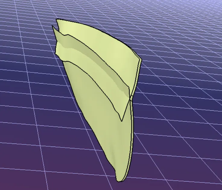
(iii) The Untrimmed surfaces should be intersecting with each other. If not intersecting extrapolate the surfaces.
(iv) The thickness of the component is to be maintained at 2.5mm. So Offset the Extrapolated surfaces setting 2.5 mm as the offset value.
(v) Trim the surfaces as per the shape of the Class A surface.
(vi) Create fillet for the component as per the class A surface. Measure the edge of the fillet value from the class A surface by extracting the fillet surface and untrimming the surface.
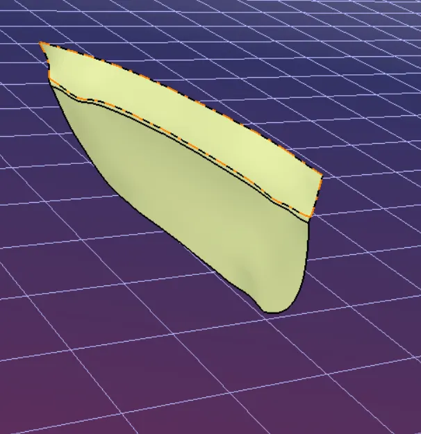
(vii) Create fillets for the class B surface and make sure the thickness between the fillet surfaces are maintained the same as the remaining surfaces.
Class C surface:
(i) Extract the edge lines for the class A surface using multiple extract option.
(ii) Create edge surface form class A surface using sweep option. Set the sweep mode to draft direction, select the extracted lines as guide curves and the tooling axis as the draft direction. Set the sweep angle as 3 degrees and the length of sweep more than 2.5 mm.
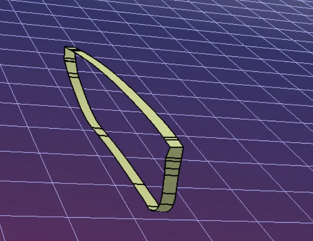
4. Now trim the class B and C surfaces as required to create a thickness of the component
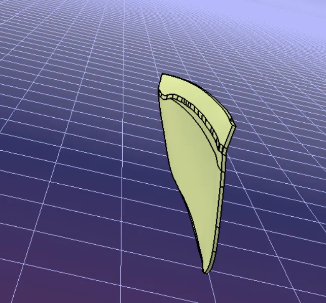
5. After trimming the Class B and C surfaces join the Class A surface together.
6.Check for any kind of open edges between the joined surfaces using the boundary feature. Fix the open edges if any.
7. Now create a solid component for a closed surface component using the "Closed' feature in the part design window. The solid will not be formed if there are any kind of open edges.
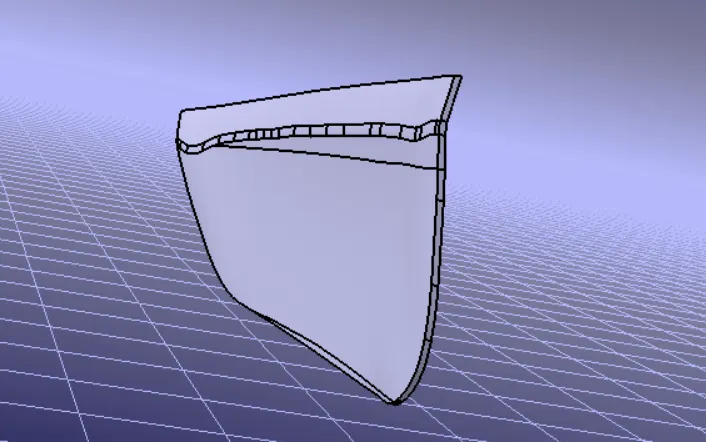
8. Another method for creating a solid component from the surface is to use the thickness option and mentioning the distance of the thickness and creating a draft angle on the edges walls of the surface as 3 degrees.
9. Create a solid component for the door attachment surface sample using the thicken option.
10. Now the engineering features i.e., locators and heat stakes should be created for the component.
Follow the steps below to create the features.
- Creating locators:
(i) There are two types of locators. They are 4 way and 2-way locators.
(ii) Considering the 4-way locater create a sketch for the locater as shown below.
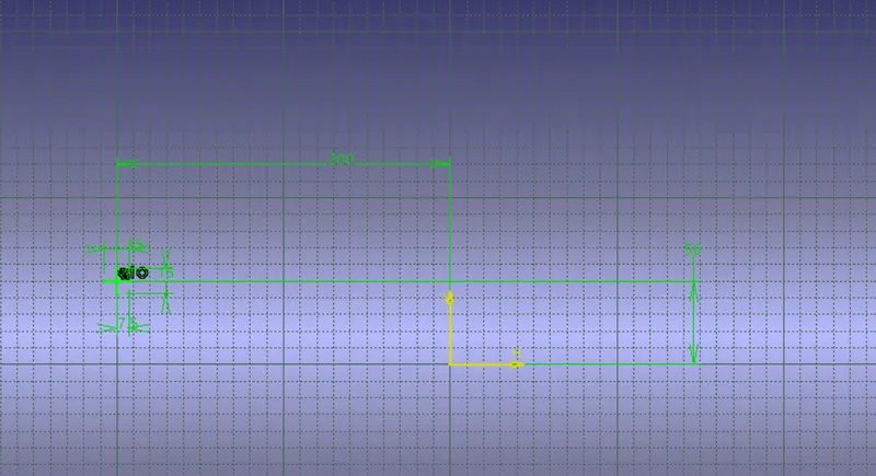
(iii) Now create a new part body for the locator and 'pad' the sketch such that it intersects through the surfaces of the door applique and the door attachment surface sample.
(iv) Create a draft for the locator walls up to 0.5 degrees as shown below.
(v) Create chamfer angles for the edges of the locater as 45 degrees and length up to 3mm. Create fillets for the edges of the components up to 0.25mm.
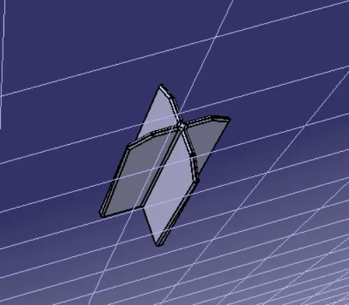
(vi) There are two locators fixed for the component. To create another locator, copy the locator part body from the tree structure and paste as special in the main root for the tree structure. Now translate the locator at the required position on the surface.
(vii) Create a two-way locator as done for the above 4-way locator except the sketch is to be created as shown below.
(viii) Now adjust the distance for all the locators equally referring to the door attachment surface sample by translating the located hight in the downward direction.
(ix) Attach the locators to the door appliqué component using unitrim option so that the extended locator length below the component will be trimmed and fixed with the solid component.
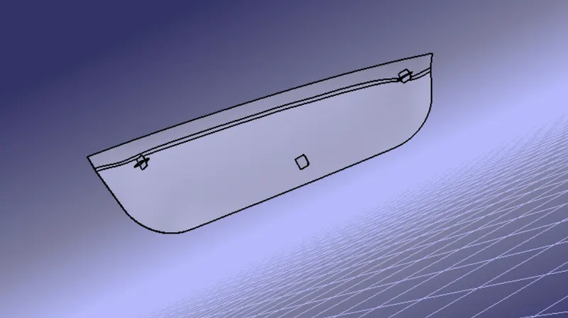
(x) Openings are to be created on the door attachment surface sample for fitting the door applique with the help of the created features. So, create a circle sketch around the locator maintaining the diameter more than Imm compared to the width of the locator.
(xi) Create a new part body and pad the circle passing through the door attachment surface sample.
(xii) Draft the created cylinder up to 0.5 degrees and translate 2 more cylinders for the remaining 2 locators as done for placing the locators.
(xiii) Now using the boolean operation remove the cylinders from the door attachment surface sample.
(xiv) The gap between the locator and the opening should be around 0.1 mm.
- Creating heat stakes:
(i) Create a new sketch for the heat stake as shown below.
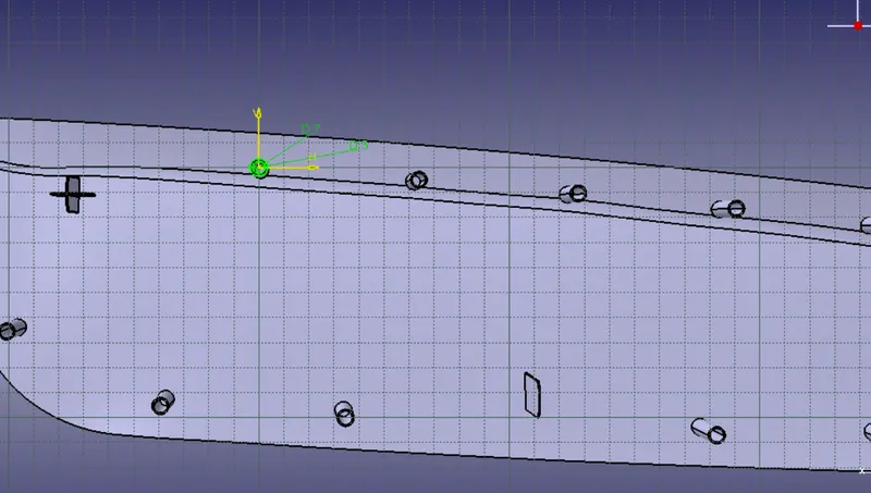
(ii) Create a new part body and pad the sketch as done for the locators. The length for the heat stakes should be less than 3 to 5 mm compared to the locators.
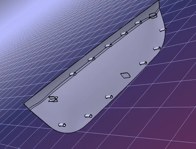
(iii) Similarly 12 more features are to be created on the door applique.
(iv) Create an offset for the boundary lines which are created in C surface creation around 5mm on the component. As shown below.
(v) Now create 12 points on the offset lines maintaining the distance around 50mm from each other.
(vi) Translate the heat stakes as done for the locator taking the created points as references.
(v) Now create the openings for the heat stakes on the door attachment surface sample as done for the locators maintaining the gap of 0.5mm between the heat stakes and the openings.
- Now the draft analysis should be done for both the featured components. For the draft analysis place the axis on the tooling axis and click on the component. The component will be hilited in green, blue and red colours. Adjust the axis such that all the three components are hilited as shown below
TREE STRUCTURE