Week 8 - Challenge 1 - Draft Analysis on a Fan Cover
AIM
To create a tooling axis for a fan cover model and perform the draft analysis on the model
OBJECTIVE
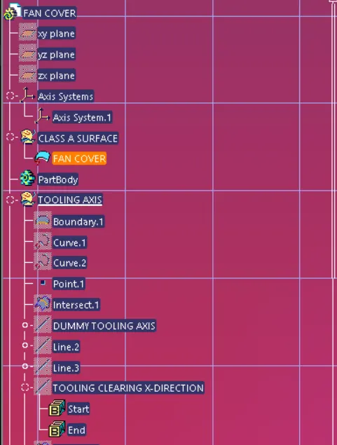
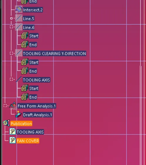
- Ensure proer tree structure
- Every sketch should be under geomentrical set only
OPERATIONS INVOLVED :-
Draft
Draft is the amount of taper for molded or cast parts perpendicular to the parting line
DRAFT ANGLE
A draft angle refers to that slant applied to the sides of most features of injection molded parts. Positioning of the injection angles is such that they run towards the direction of the mold’s pull and parting line. They help to release the molded parts from the mold easily.
BENFITS OF DRAFT ANGLE
- They are vital to ensure that molded parts meet the required quality standard. Without a draft, you increase the chances of having injection molding issues. This may unnecessarily increase the cost of production and lead time.
- A draft angle allows you to use a simple push on the ejector pins to pop your part out of the mold. This way, you will prevent the part’s surfaces from being dragged along the mold when ejected. Friction between your part’s surface and the mold’s surface can cause scratches and affect your part’s appearance.
TOOLING DIRECTION
The Tooling Direction is basically the direction that the mold pulls apart. The mold is built in two separate pieces, basically. You have a Cavity side and you have the Core side. The Core pulls apart from the Cavity and that's the Dyeline or the Tooling Direction.
STEPS FOR DRAFT ANALYSIS
STEP 1
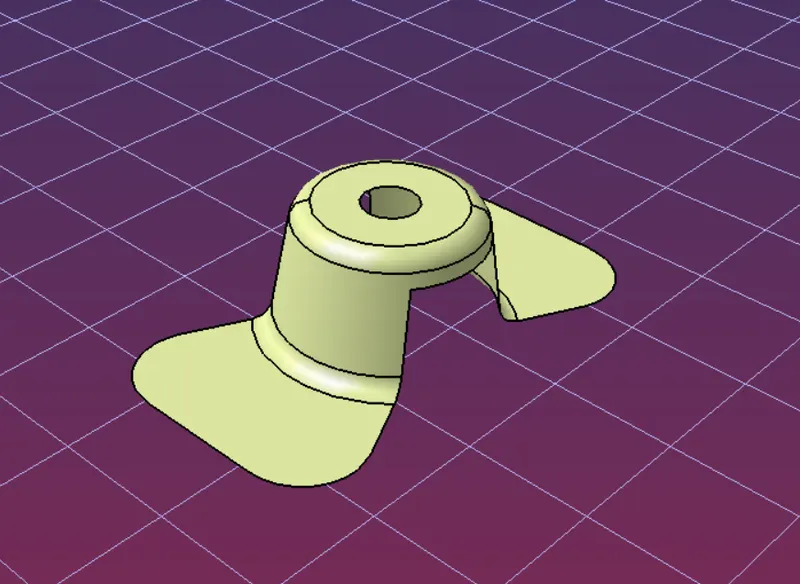
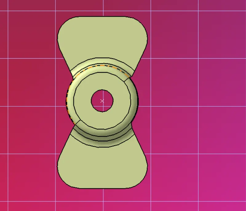
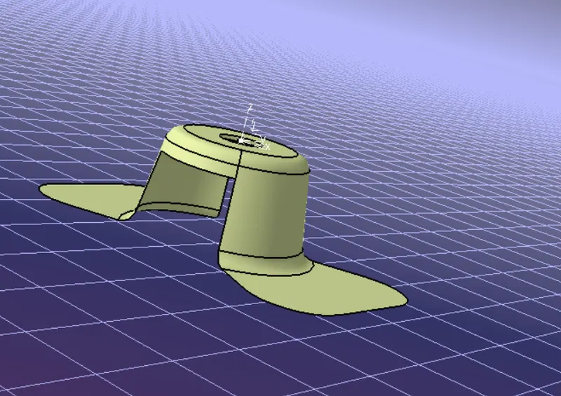
To import the given class A surface model in this case fan cover model in catia v5
STEP 2
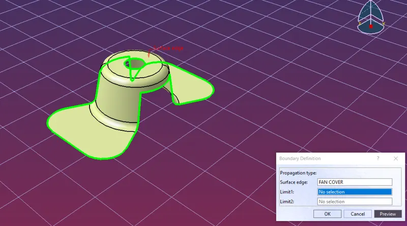
After importing check for the connectivity of all the surfaces on it.join operation,boundary operation and disassemble it
STEP 3
To create a tooling axis first create a dummy axis in the z-direction by creating a center point using a hole as reference in the point tool.In order to create tolling axis clearing the direction which need to create a axis which needs to create a axis system at the centre
STEP 4
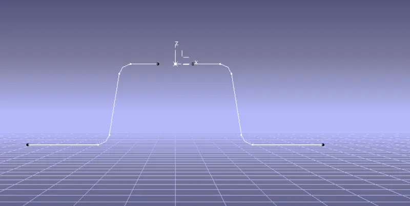
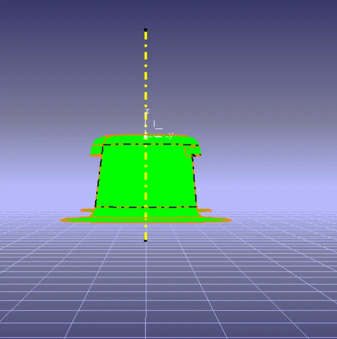
Now using intersect option,select the zx plane of the axis system and fan cover or class A surface,this will give a 2D sketch of fan cover viewing in X-Direction
STEP 5
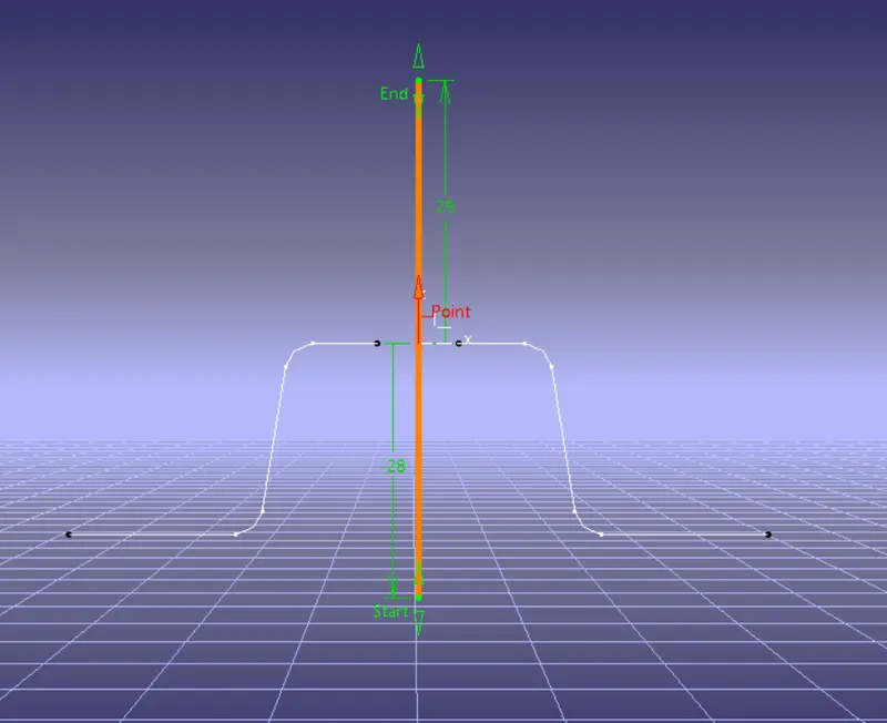
Create a dummy axis
STEP 6
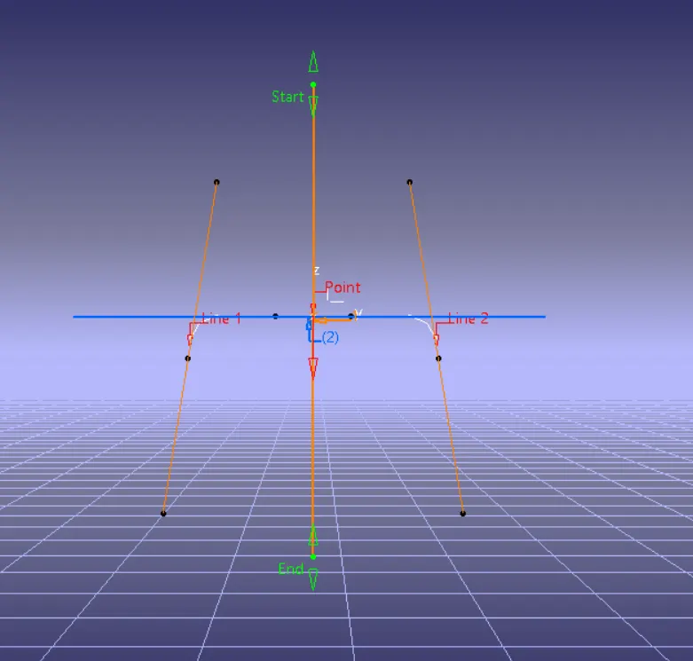
Now create lines representing the walls of fan cover
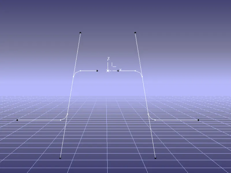
STEP 7
Using the 2 lines create a tooling axis clearing X-Direction with the help of bisecting command
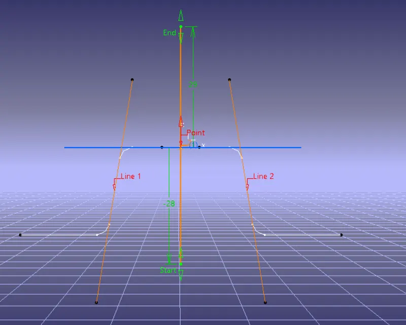
STEP 8
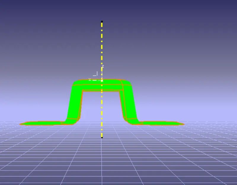
Now again using intersect option,select the yz plane of the axis system and fan cover or class A surface,this will give a 2D sketch of fan cover viewing in Y-Direction
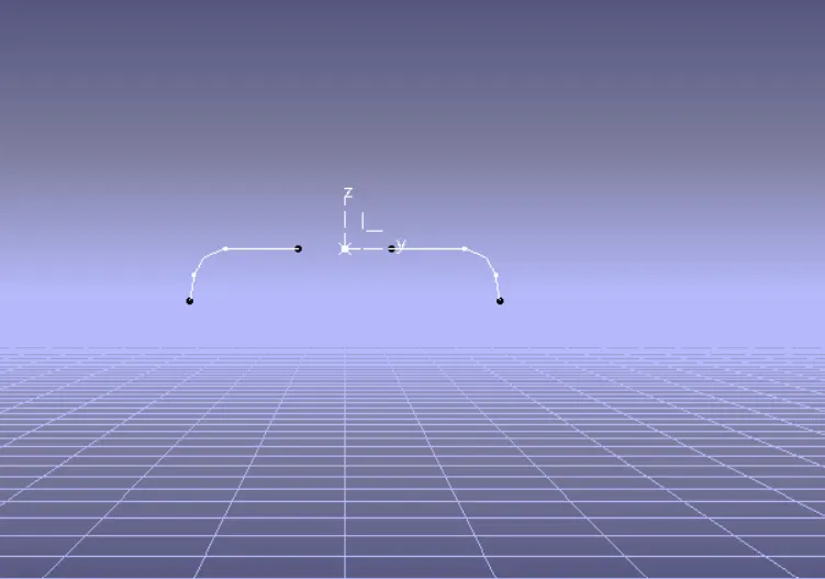
STEP 9
Now create lines representing the walls of fan cover and Using the 2 lines create a tooling axis clearing Y-Direction with the help of bisecting command.
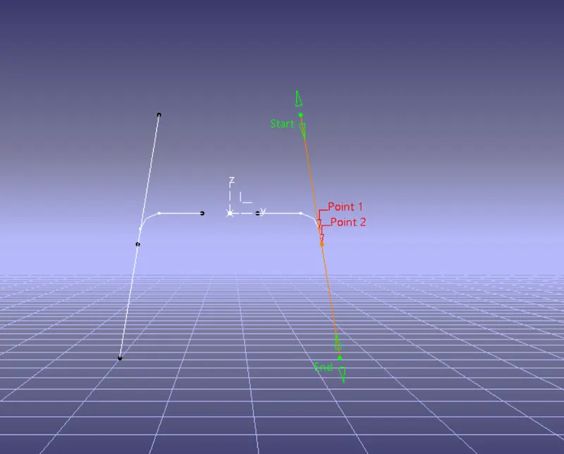
STEP 10
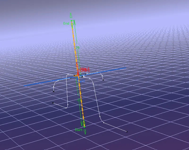
Now create the final tooling axis in Z-Direction by bisecting both X and Y direction clearing axis as reference
STEP 11
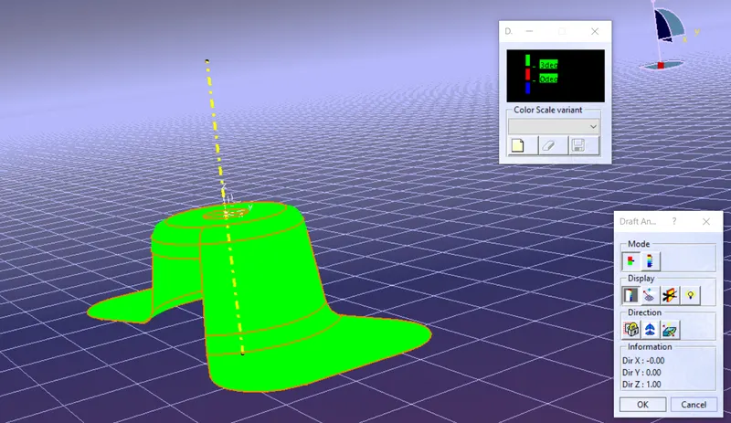
To perform draft analysis click on feature draft analysis option,To give the draft direction,use the compass and align Z-Axis of it with the tooling axis.Once it properly aligned lock the draft direction.A red point shown icon on the screen ,select the class-A surface and it will show us the current of the model.Then go to the display tab on draft analysis and select the first option under it colour scale and it will show the draft value,set the draft value to 3 deg under the colour scale variant and press ok.
STEP 12
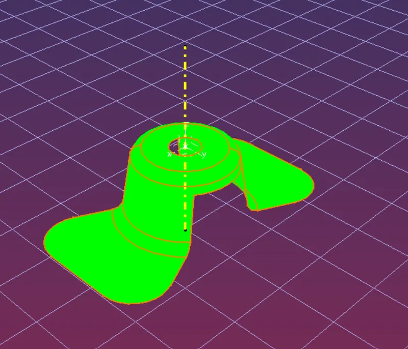
To publish the tooling axis and the class-A surface first select it and go to menu bar-Tools publication.This will publish the tooling axis and class A surface whuch can be seen in the tree
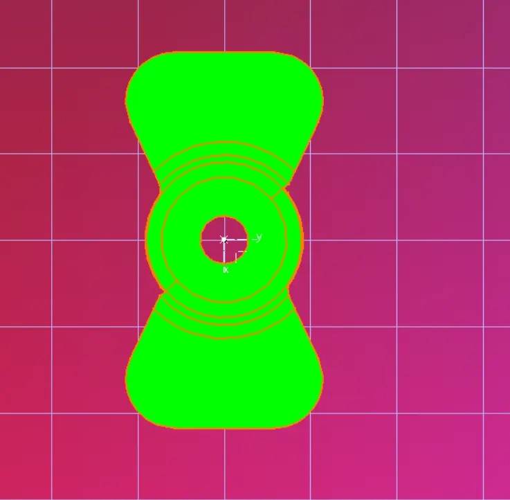
FINAL MODEL VIEWS.
TREE STRUCTURE