Week 9 - Project 1 - Door Applique Design with Engineering Features
AIM: To create a plastic design, Tooling axis, Draft angle and perform draft analysis for the given door applique class A model.
PROCEDURE:
- Open CATIA V5 and open the class A CATPART of the Door applique in generative shape design module.
- Check the class A surface for any openings are available or any errors are their on the class A surface using Boundry tool.
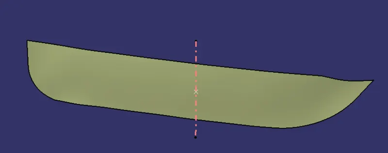
- Now create the tooling axis by taking a point with respect to the surface and draw a line passing through the point and perpendicular to the surface by taking the reference of point and Y-direction and it is our required tooling axis.
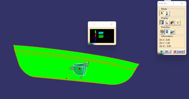
- Now perform draft analysis to the class A surface with respect to the tooling axis.
- After the draft analysis start creating the B surface.
- Extract class A surfaces and untrim it after that give extrapolation and offset the extrapolated surfaces with a limit of 2.5mm.
- Now measure the fillet radius from the class A surface and give fillet to the joining point of the surfaces in class B.
- Now create the class C surface by extracting the boundry of class A surface.
- Using smoothe curve clear the unwanted points on the boundry and make it a smoothe curves with two ponits starting and ending.
- create the class C surface using sweep with a draft angle 3 degrees with reapect to the tooling axis.
- Join the class A and class C surfaces using join tool and trim it with the B surface.
- Now go to the part design and make it into solid part using close surface.
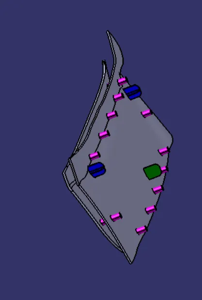
- Now create the locators(4 way locator, 2 way locator) and heat stakes to the door applique.
- Create a point at the centre of the surface of door attachment and plane with respect to the point and parallel to the surface of the door attachment.
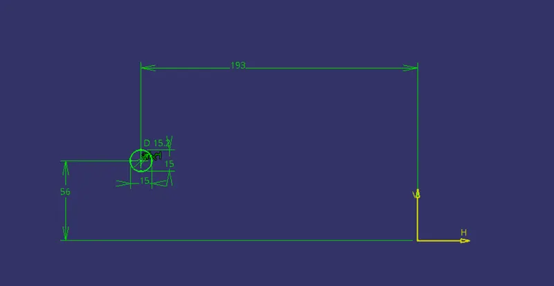
- Go to the sketcher and create a sketch for the four way locator with reference to the plane.
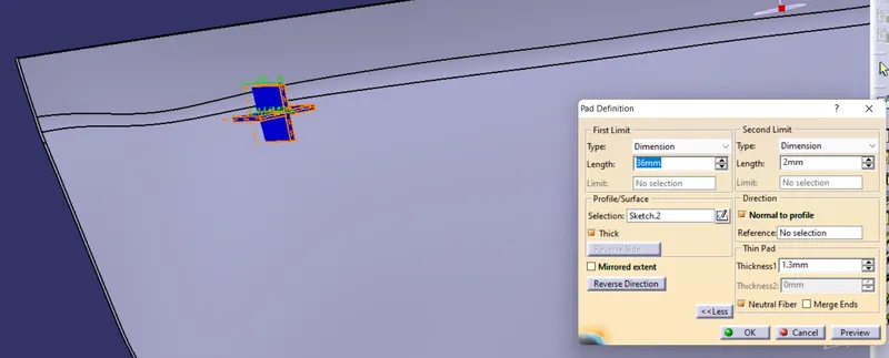
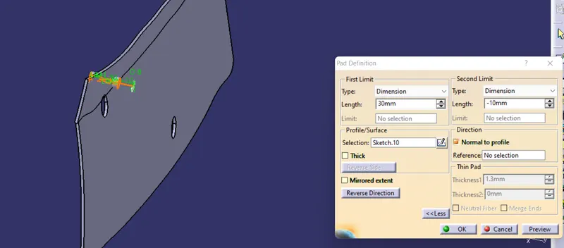
- Now pad the sketch by giving its constraints height and thickness to be padded with neutral fibre which gives equal thickness at both sides of the line which is padded.
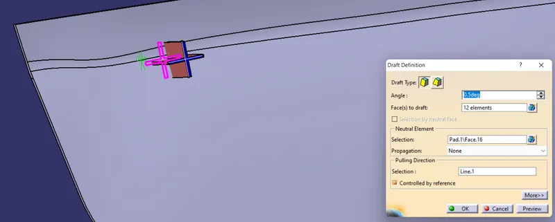
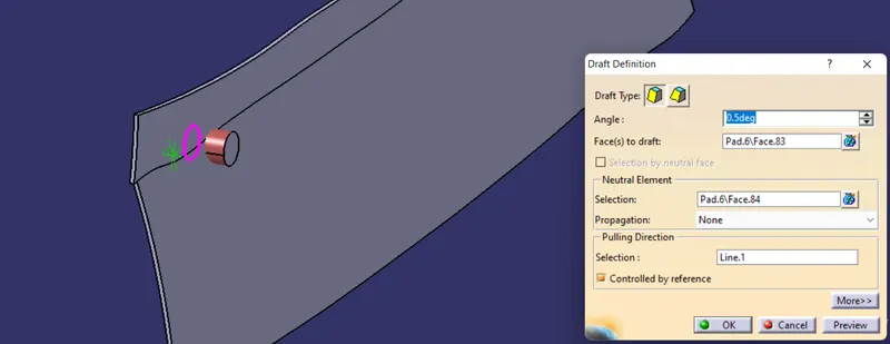
- Draft the faces using drafting tool on all the faces except base and base be the neutal face with respect to the tooling axis which is the pulling direction.
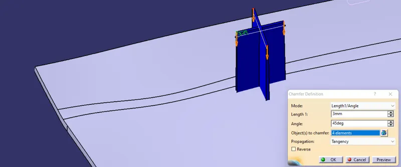
- Chamfer the top edges of the locator with angle and length.
- Copy the above part body and paste it with special operation as result with link.
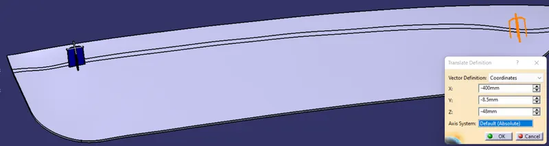
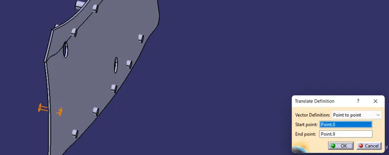
- from that above link translate the body at a certain distance from the original loactor where it has to be placed.
- Now perfrom boolean operation to the above part bodies to the solid door part using union trim, trim the loactors with the solid door part.
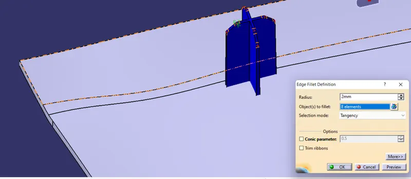
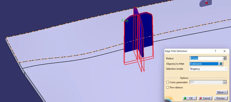
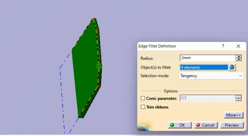
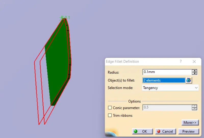
- Now give the fillet to all the edges of the locator.
- Repeat the same process to the two way locator also.
- Now create the heat stakes with reference to the solid part.
-
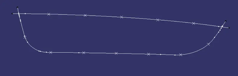
Offset the Class A surface to 2.5mm and extract the boundaries of the offsetted surface.Parallel Curve the extracted boundaries by Parallel Curve.
-
Give the Points Repetition to the Parallel curves by Points and Planes Repetition by : Curve - Parallel curve,Parameters - Instances and Instances - no of points.NO Heat stakes should present nearer to Locators.
-
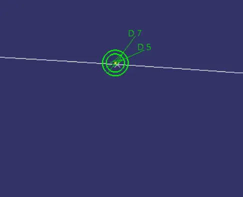
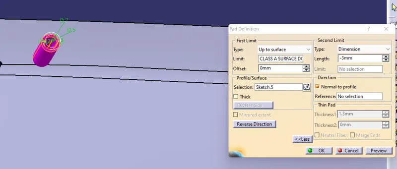
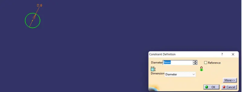
Now create a sketch on the point created on a Parallel curve.Draw the circles with diameters of 5mm and 7mmand in Part Design,Pad it .
-
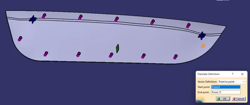
Copy the Part body of the Heat Stake and Paste it Special with reference link and then Replicate to the pointswhich are created by Translate option, Translate the part body of Heat Stake to the other point which was copied by selecting the start point and endpoint.
-
By Boolean operation, Assemble all the Heat stakes part bodies in a single body and then Unitrim the Heat Stakeswith the Solid body of Door Applique by selecting the faces to keep.The distance between the tip surface of locatorand Door Attachment surface should be equal for all locators, Also the height of Heat stake should be smaller thanthe Locators.
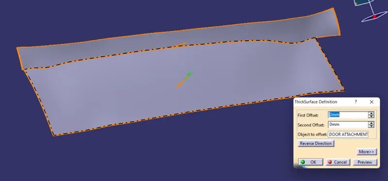
- Thick the door attachment by using thickened tool.
- Now create a clearence holes on the door attachment for the locators and the heat stakes.
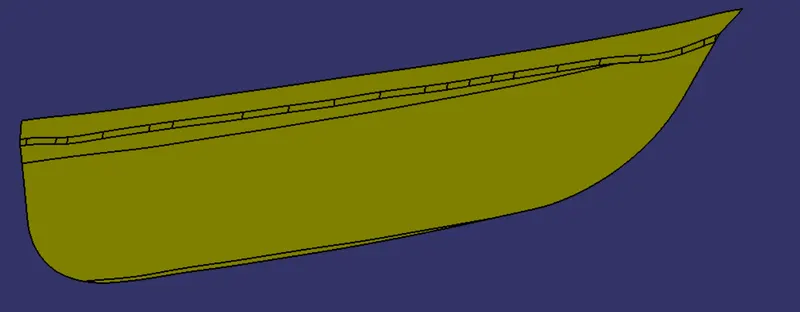
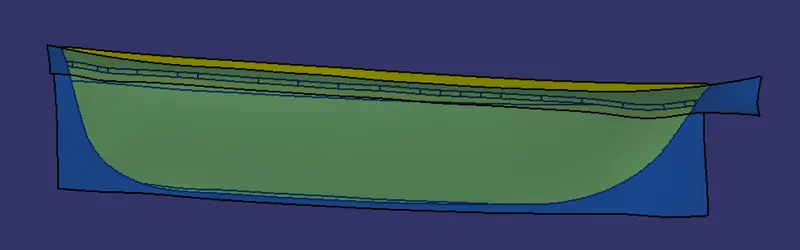
Class A surface:
Draft analysis:
Tooling axis:
Extract-untim-extrapolate
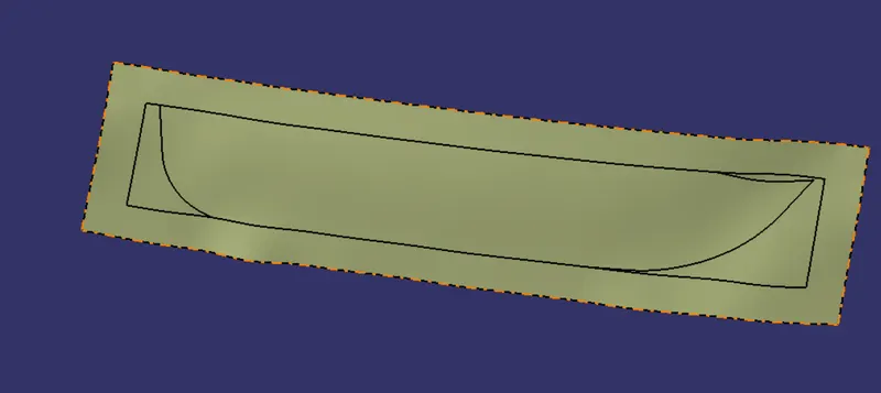
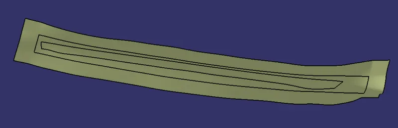
Offset:
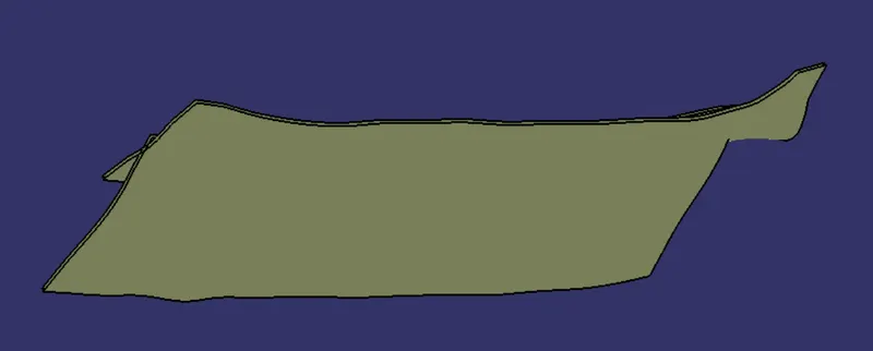
Trim:
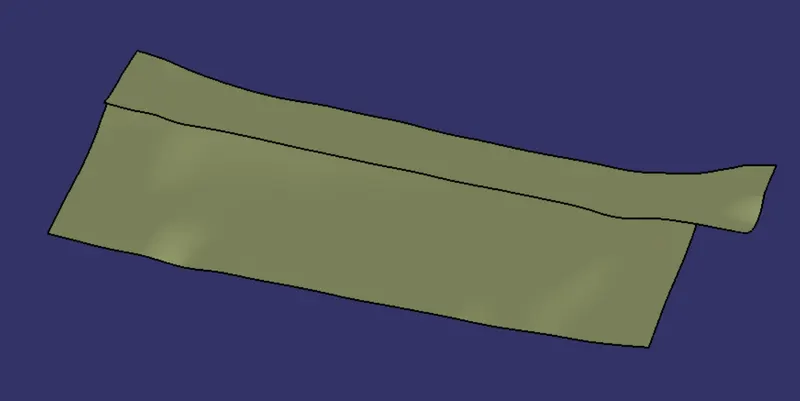
Fillet:
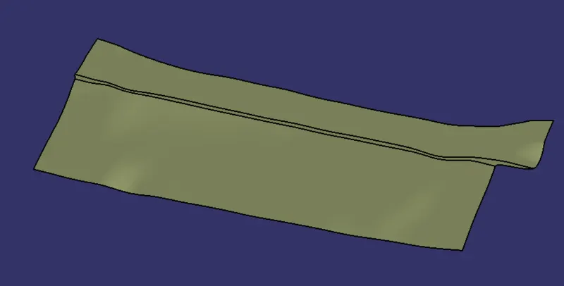
Boundry:
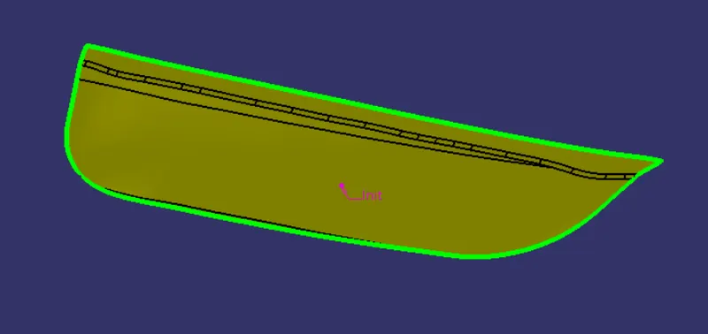
Smoothe curve:
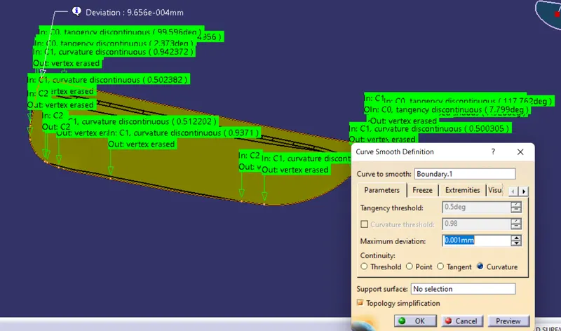
Sweep:
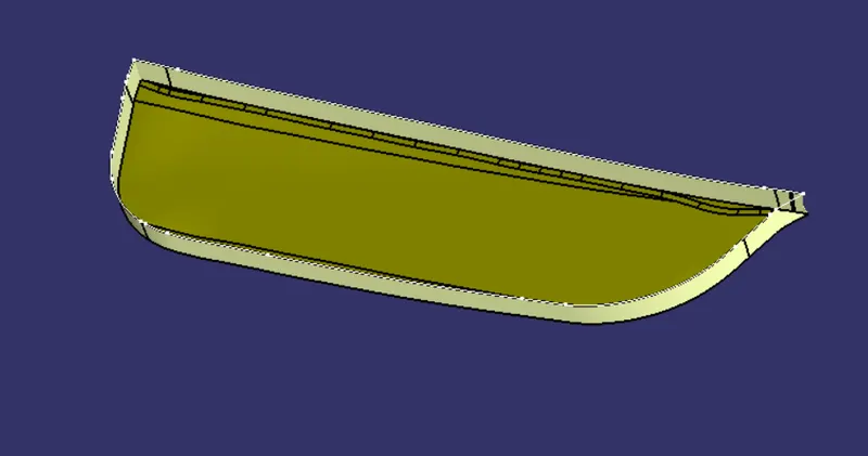
Join:
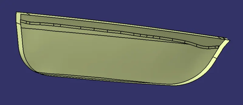
Trim join and B surface:
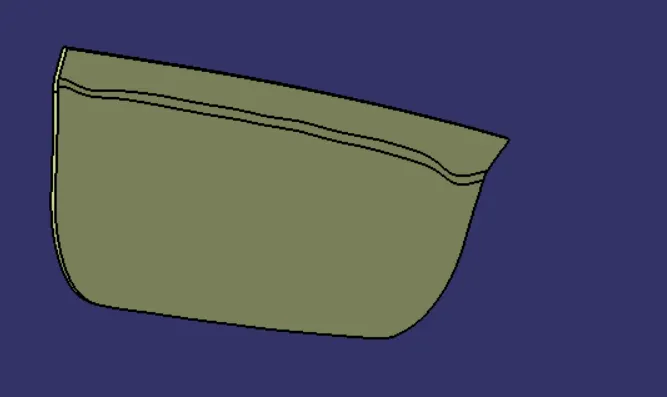
Close surface:
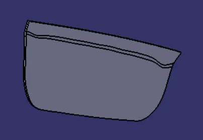
4 way locator:
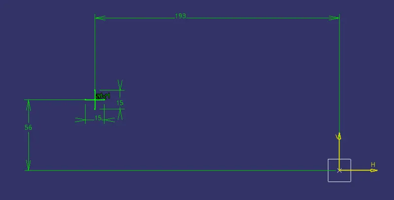
Pad:
Draft:
Chamfer:
Fillet:
Translate:
2 way locator:
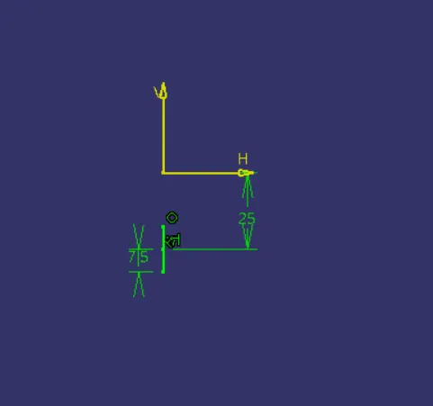
Pad:
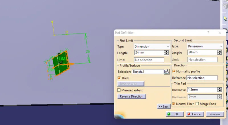
Draft and chamfer: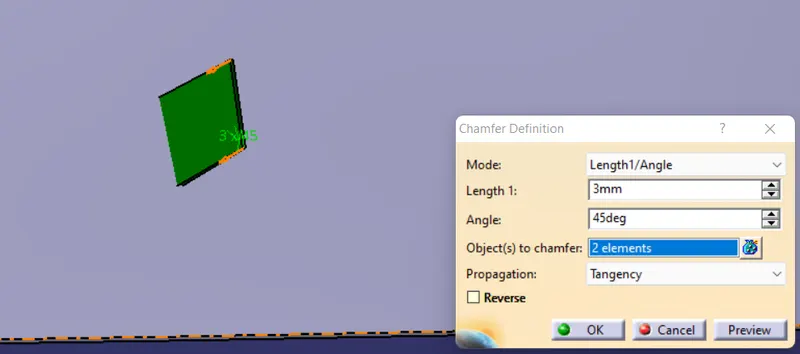
Fillet:
Boundry and parallel lines:
Heat stake:
Pad:
Translate:
Thickness: door attachment
Locator clearence hole:
Heat stake clearence hole:
Final output:
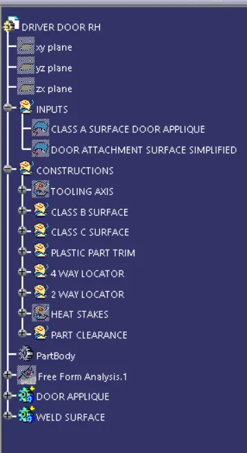
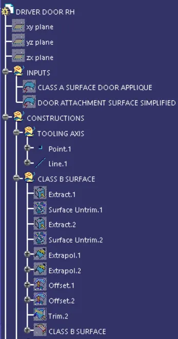
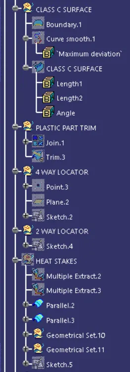
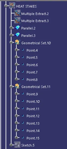
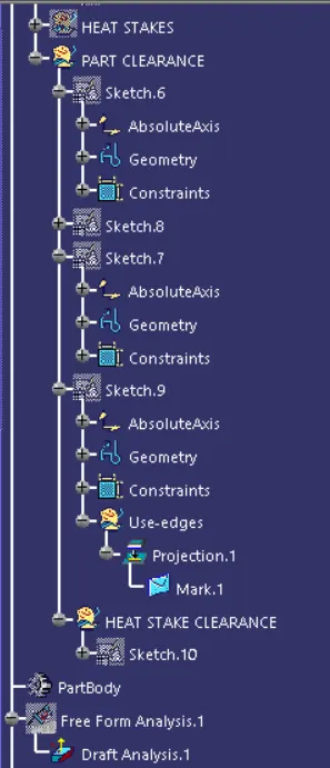
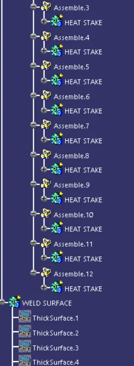
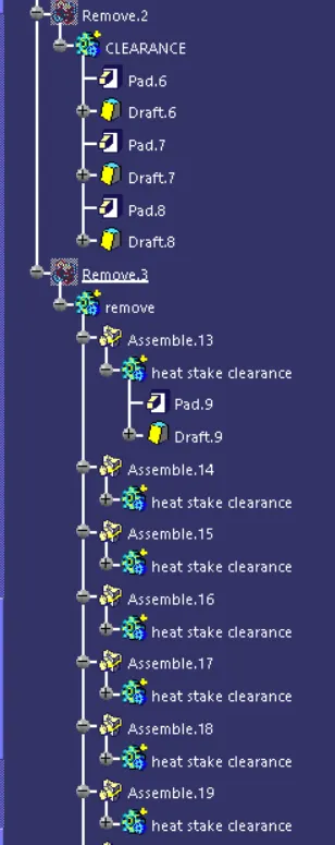
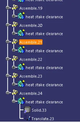
Tree: