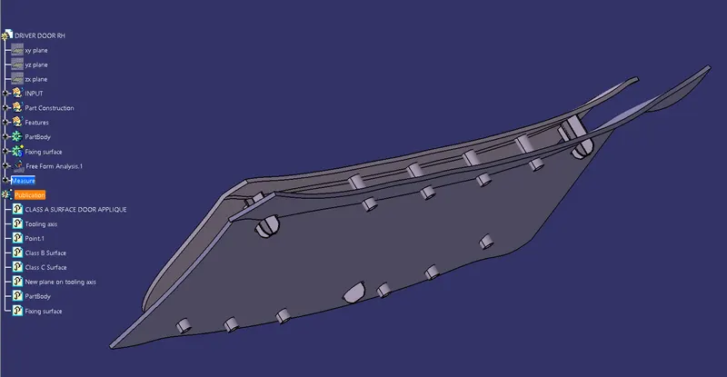
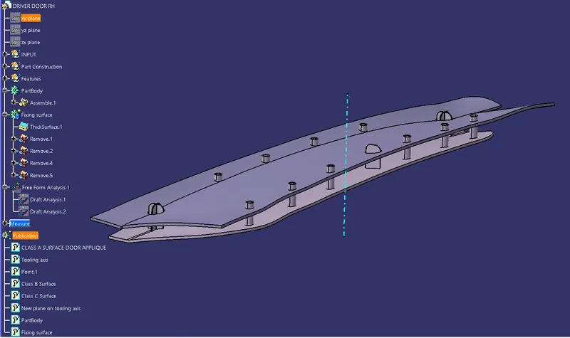
Week 9 - Project 1 - Door Applique Design with Engineering Features
Aim :
To create the Door Applique Plastic component through the given Class-A surface. To begin with, the tooling axis for the given Class-A Surface should be created meeting the requirements of the draft angle and at the end perform the Draft analysis on the model.
Tooling Axis :
For toooling axis the base of the class A surface is extracted and a point is created on the middle of the surface using Point -> On surface -> 0mm (location). Then draw a line using line command using point direction option. Basically such lines are considered as dummy tooling axis here we are considering that as tooling axis.
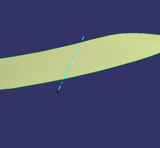
Class B Surface :
To create class B surface either we can directly offset the given surface or we can extract the surfaces from class A surface. Here i have extracted the surfaces which are not fillets from the class A surface and extrapolated it inside a new geometrical set. Then i have trimmed it and gave a minimum fillete value of 0.25mm.
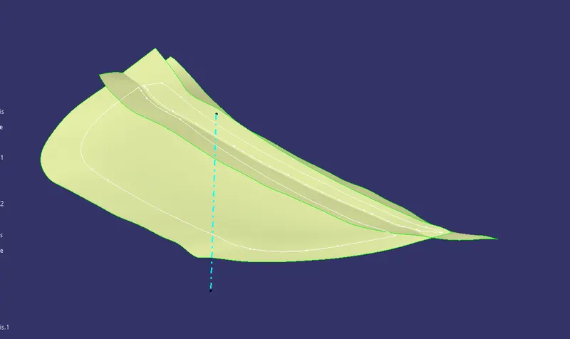
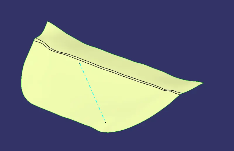
Now the trimmed surface is offsetted to a distance of 2.5mm Which becomes the class B surface of the given part.
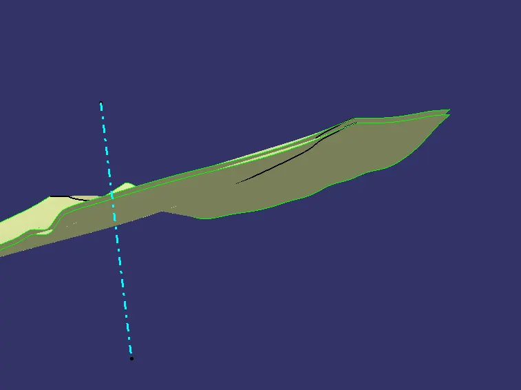
Class C Boundary :
To create Class C Surface the boundaries from the given class A surface is extracted in a new geometrical set either using boundary option or multiple extract option. Here i have used boundary option the the extracted curve is curve smoothened using curve smooth option with minimum curvature value as 0.001mm.

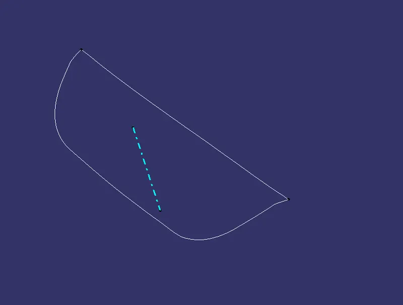
Class C Surface :
Now the curve smooth is swept to create class C surface , with thye sweep angle of three degree with reference of tooling axis.
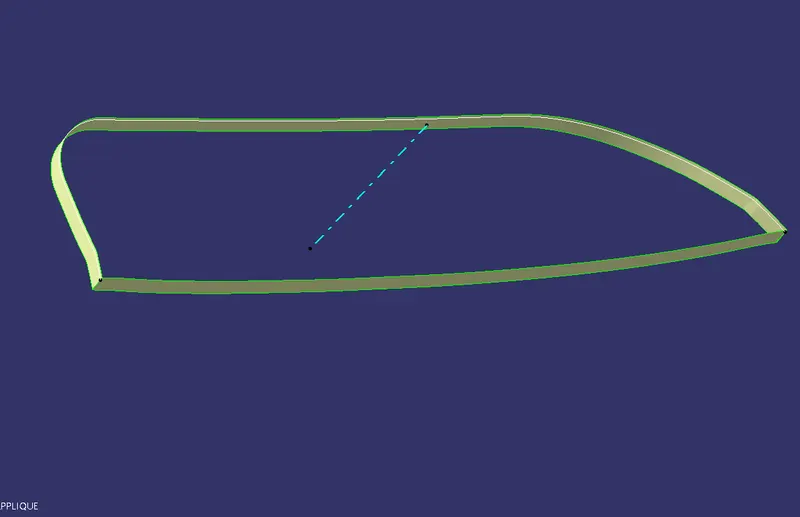
Now the swept surface will not be connected , there will be a minimum gaps at the end , which is extrapolated seperately then trimmed with each surface.

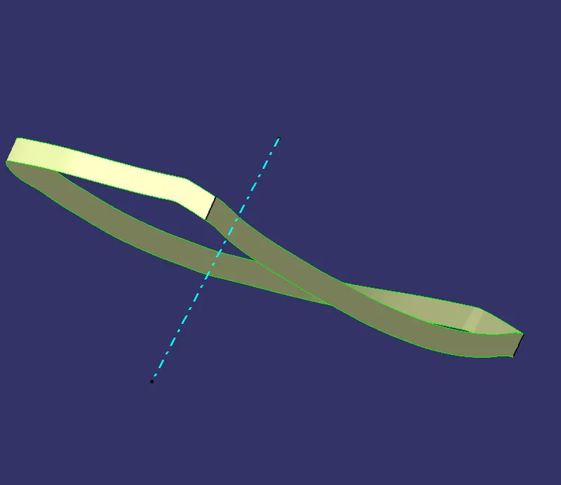
Joining Class A and C surfaces :
Both the Class A and C surfaces are defined and trimmed inside a new geometrical set named as trims and the join is named as Class A & C .
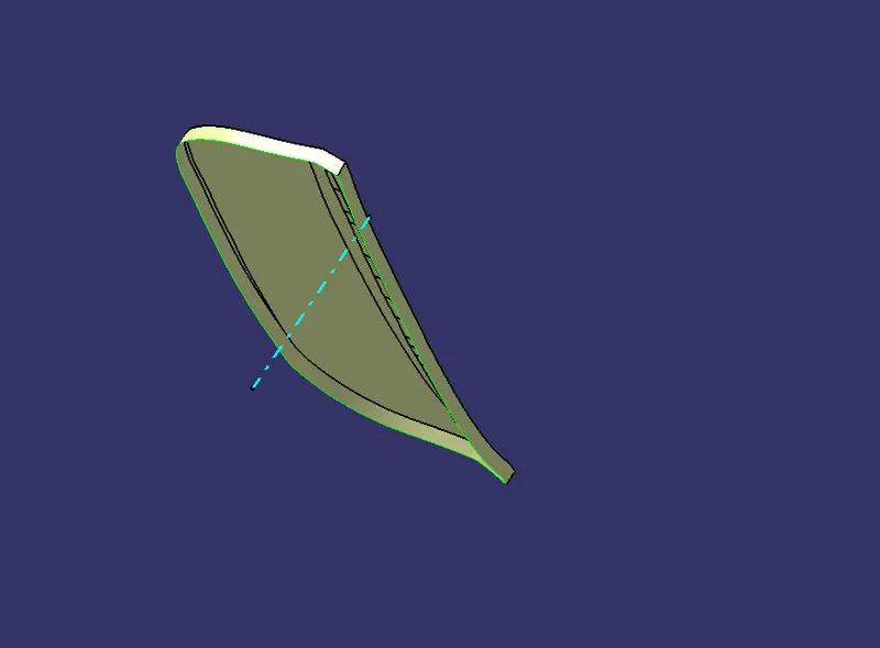
Final trim :
Now the A & C surface is trimmed with the class B surface to create the final part and is converted to solid body using clossed surface command in part design work bench.
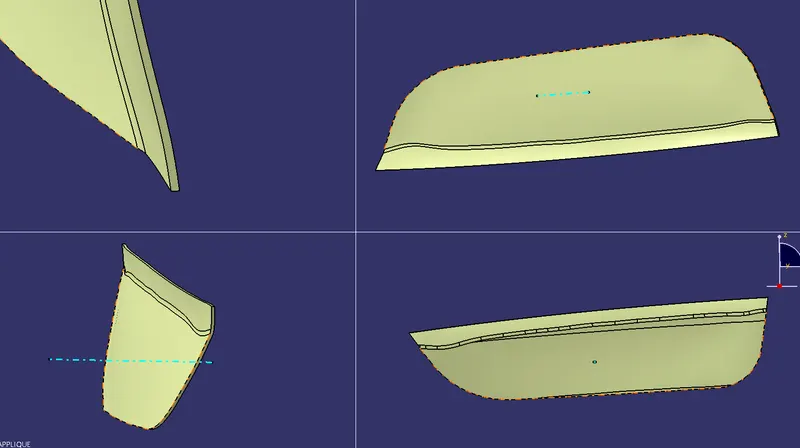
Heat Stakes :
To create heat stakes we need points or positions in which the heat stakes must locate. These heat stakes will be attached on the Class B side of the part body and are considered as Class B Features.
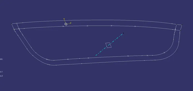
For this parallel curves for the curve smooth are created and points are placed on the parallel curves . Scince the parallelm curves will have dis continuity we need to create smooth curve with curvature continuity value as 0.001mm. Also considerenig the spacing between the two heat stakes there must be a gap between 50mm to 80mm based on the size and gap of the partbody.
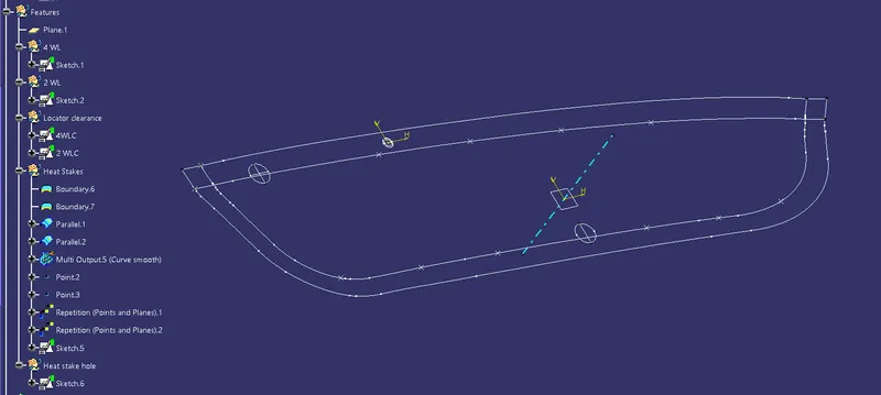
Profile for the heat stakes is drawn which basicall two circles with smaller dia as 5mm and larger dia as 7mm as respective inner and outer diameters of the heat stakes. Heat stakes are permanent joints for the plastic body like the revet joints in sheet metals.
Locators :
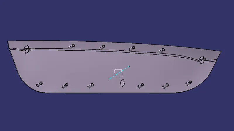
Locators are classified into multiple types here we use two types of locatos
- Four way locator.
- Two way locator.
Four way locators have four ribs interconnected to make like a cross or add symbol in mathematics locators must obey all the design rules defined for the ribs like draft , rib tip thickness, rib root thickness, fillets , and chamfer values.
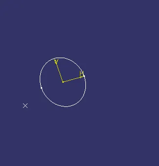
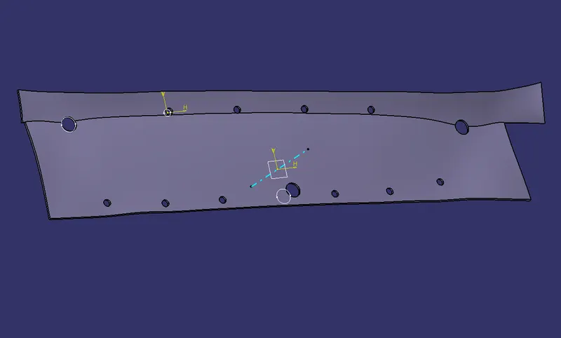
Clearance for the heat stakes and locators are created in the fixin portion of the part body, which is the portion or part in which the part body will fix. There is a cetain criteria for clearance hole value of heat stakes and locators.
- The gap between the side face of the heat stake and the clearence hole of heat stakes on the fixing surface must be 0.5 mm.
- The gap between the side face of the locator and the clearence hole of locator on the fixing surface must be 0.1 mm.
Draft Analysis :
Since all the B side features of the part body should obey the draft analysis, draft analysis id done with tooling axis as reference.
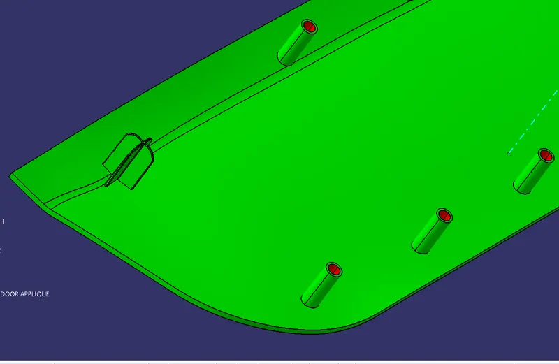
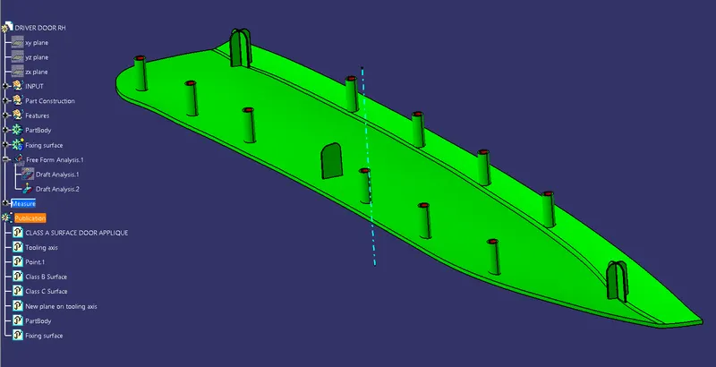
Final part body with fixing surface, locators and heat stakes.