Week 9 - Project 1 - Door Applique Design with Engineering Features
1).
Aim:
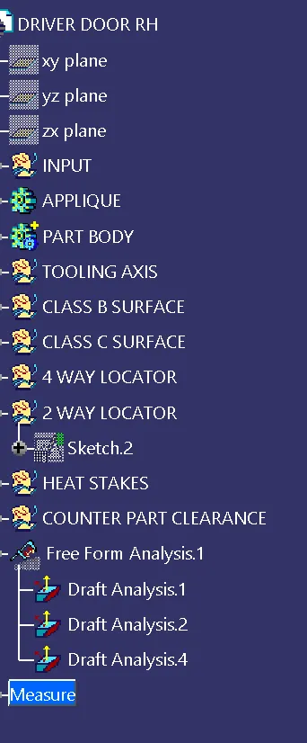
Create door appliqué from given class A surface. Then create attachment feature like locators & heat stake considering the design rules. Perform draft analysis on class A surface as well as final component.
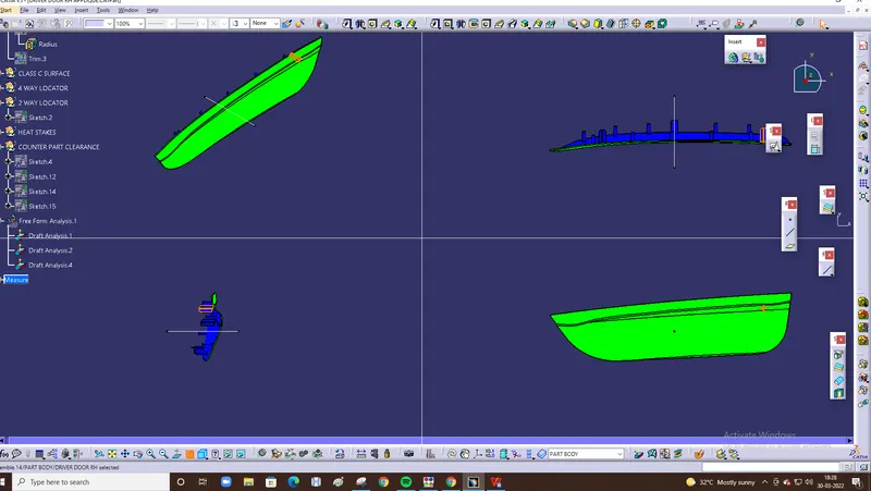
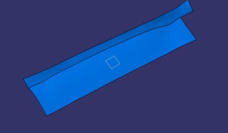
Door appliqué surface:
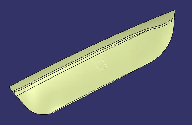
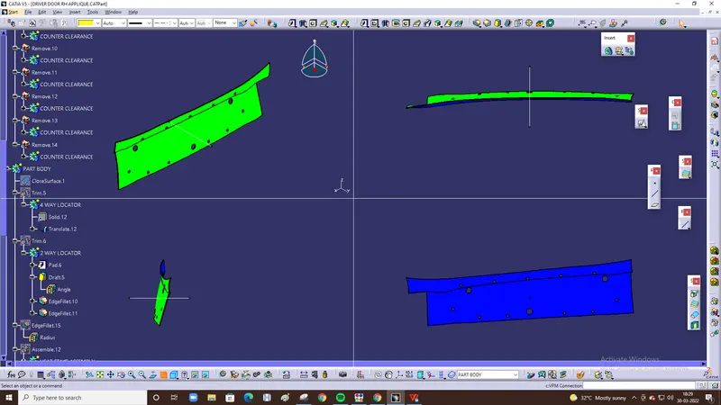
Door attachment surface:
Theory:
Heat stakes:
In manufacturing products with thermoplastic components, it is often necessary to join a thermoplastic to a part of dissimilar material, whether it to be metal, a dissimilar plastic or other material.
Thermal staking is an assembly method that uses the controlled melting & reforming of a plastic stud or boss to capture or lock another plastic or metal component of an assembly in place. The plastic stud protrudes through a hole in the component to be locked in place. The heated thermal tip contacts the top of the studs, which melts & fills the volume of the tip cavity to produce a head, locking the component in place
3-2-1 Principle of Location-
The 3-2-1 principle of location (six point location principle) is used to constrain the movement of work piece along the three axes XX, YY, and ZZ. This is achieved by providing six locating points, 3 pins in base plate, 2 pins in vertical plane and 1 pin in a plane which is perpendicular to first two planes.
The degree of freedom defines as the capability of a body to move. Consider a rectangular box, in space the box is capable of moving in twelve different directions (six rotational and six axial). Each direction of movement is counted as one degree of freedom.
i.e. a body in space has twelve degree of freedom.
Above figure shows a body in space and its possible direction of movement. The body can move two directions along the each axis of three mutually perpendicular axes; also can rotate about this axis either clockwise or anticlockwise. There are twelve degree of freedom for a body in space.
In machining process, in order to attain specific results, the degree of freedom is constrained by using work holding devices, jigs and fixture and locating devices.
M ethod followed:
- Checkingcontinuity of class A
- Decidingfeasible tooling direction & creating tooling
- Performingdraft analysis on class A
- Creatingclass B surface from given class A
- Creatingclass C surface to join A & B class
- Creatingsolid feature by using closed
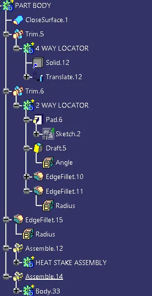
- Creating4 way & 2 way
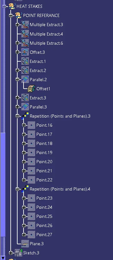
- Creating heat
- Creatingclearance holes for locators & heat stakes on attachment part
10 Performing draft analysis on final component
- Checkingcontinuity of class A
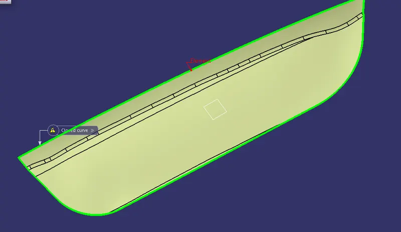
We have to check continuity of given class A surface to ensure class A surface is properly joined or no discontinuity present. This can be done by using join or boundary command. By looking visually in below image we see that surface has continuous connected boundary as highlighted by green.
- Creating tooling axis direction:
Tooling axis is created by bisecting method. First analyze model. Check tool clearing direction i.e. X, Y or Z. Perpendicular faces to tooling direction will not create promblem. we have to look for inclined faces. Take the intersection of inclined faces with the respective plane. Create line on that inclined faces. Finally make bisecting line between inclined line.
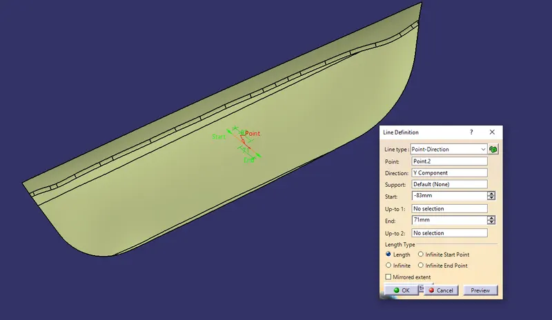
But in this door applique, class A has most of the flat surface. So we have to create tooling direction perpendicular to it i.e. in Y direction. Create point at the centre of class A surface by using point command & create a line passing through that point in Y direction & publish it as tolling axis.
3. Performing draft analysis on class A surface:
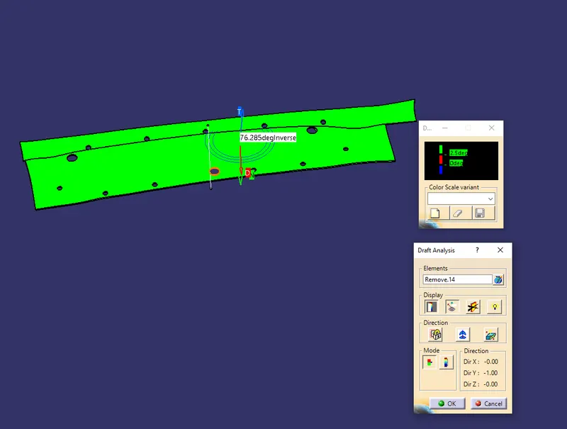
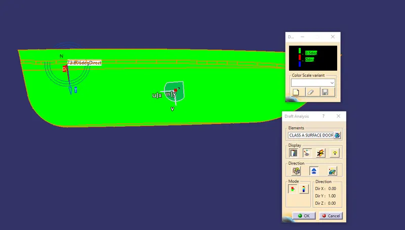
To perform draft analysis. Go to insert < Analysis< Feature draft analysis.
Switch customize view parameter mode to
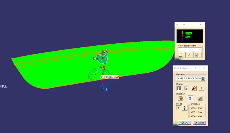
Click on compass icon & align it with the tooling axis & click on the surface, we will get our results.
Color scale variant of draft analysis:
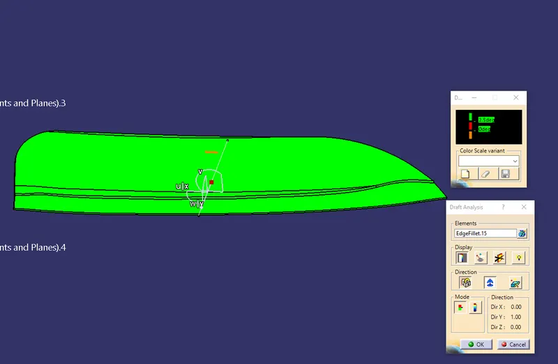
From the below image it is seen that surface in green color has 2.5 draft which is most required for tooling feasibility. Also see color variant display box. we provided all green color surfaces have +ve draft value also blue color surfaces shows 0° draft whereas surfaces in red color have draft.
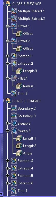
4. Creating class B surface from given class A surface.
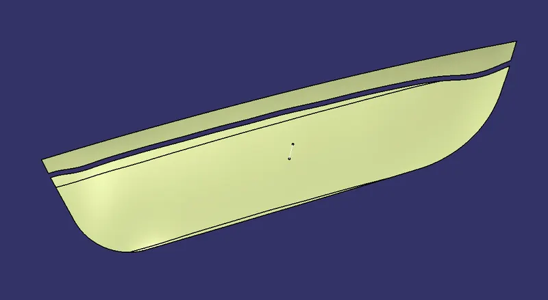
Dividing class A surfaces in two as shown by different color & extract them separately.
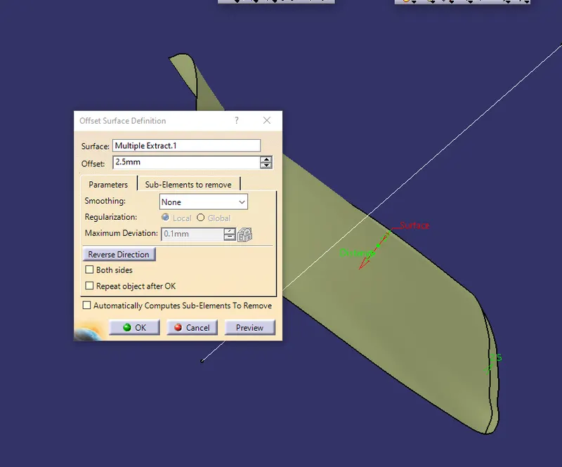
Offset it by 2.5mm as thickness of component.
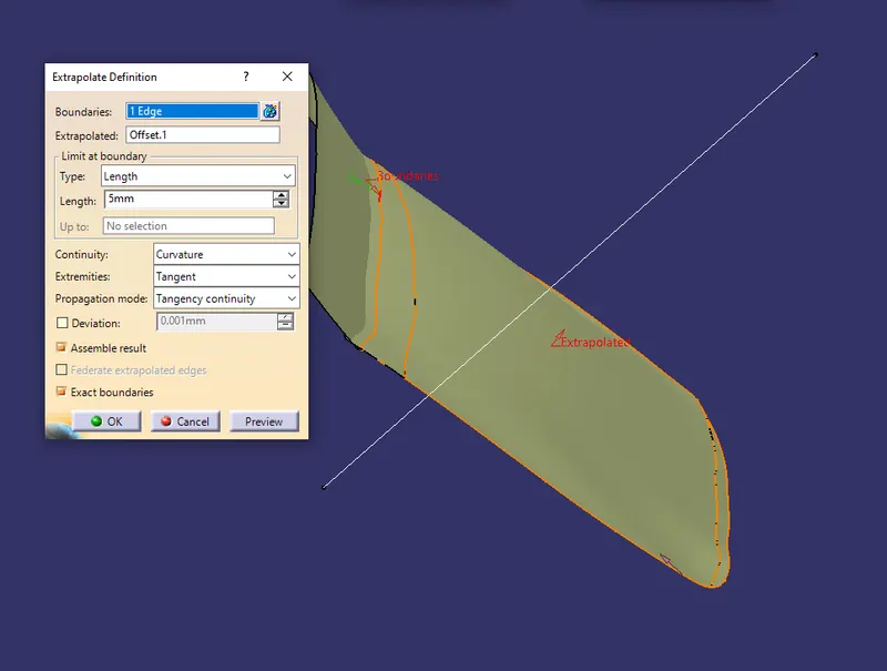
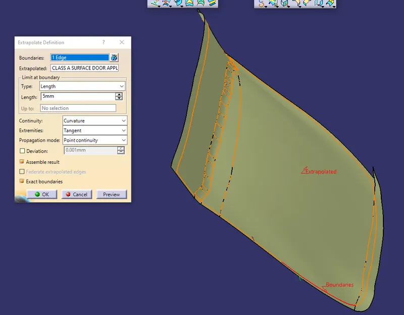
Extrapolate both surface 5mm with tangent continuity so these surface intersect with each other.
Apply bi-tangent fillet to these surfaces. Measure class A surface fillet. It is 13.5 mm. so keep fillet value 11mm (class A surface fillet – thickness of component).
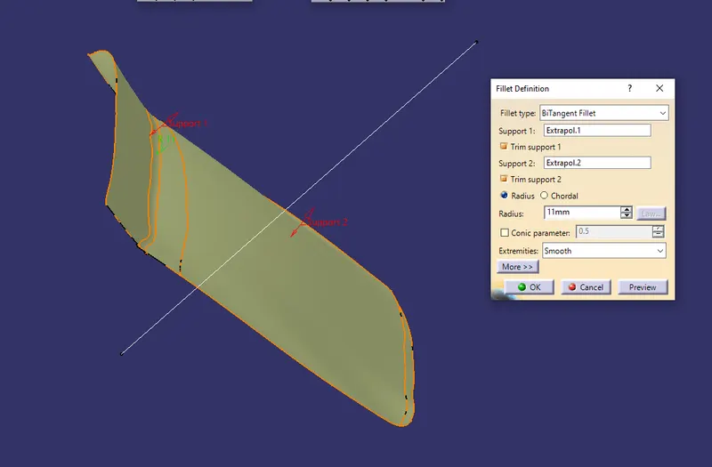
Extrapolate filleted surface over the all boundaries at value 5 mm to have intersection with class A & C later. This is B class surface. Now publish it.
5. Creating class C surface to join class A & B surface
Extract the boundary of the class A surface in two separate curve. To do this we have to give limiting points in boundary command pop up box.
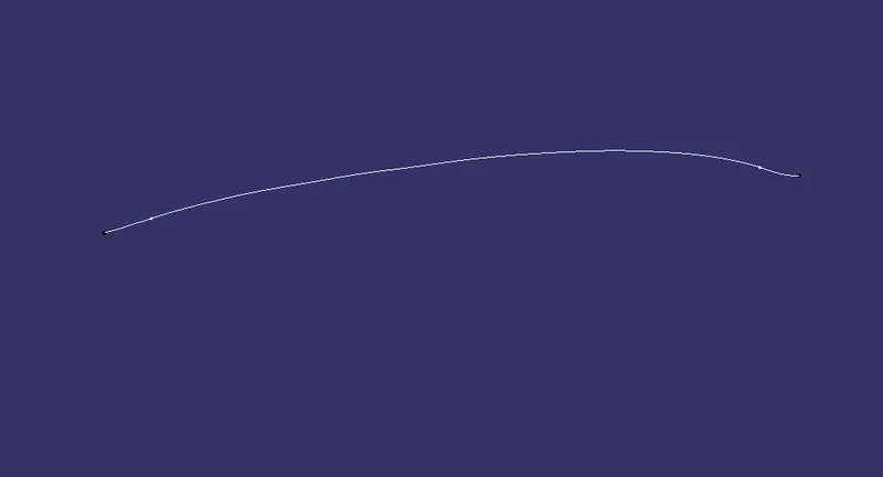
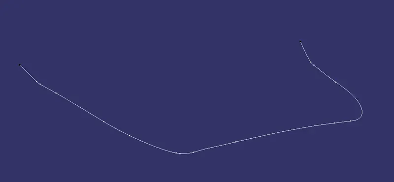
Then sweep these curve along main tooling direction with 3° draft. So we get two surfaces.
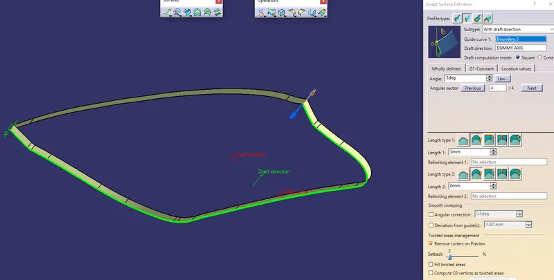
But we observe gap between these two surfaces that these surfaces not intersecting with each other. So we have to extrapolate these surfaces at both ends to intersect with each other.

Trim these together to get final C class surface.
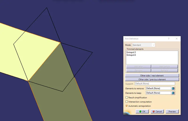
TRIM Class A & C surface together
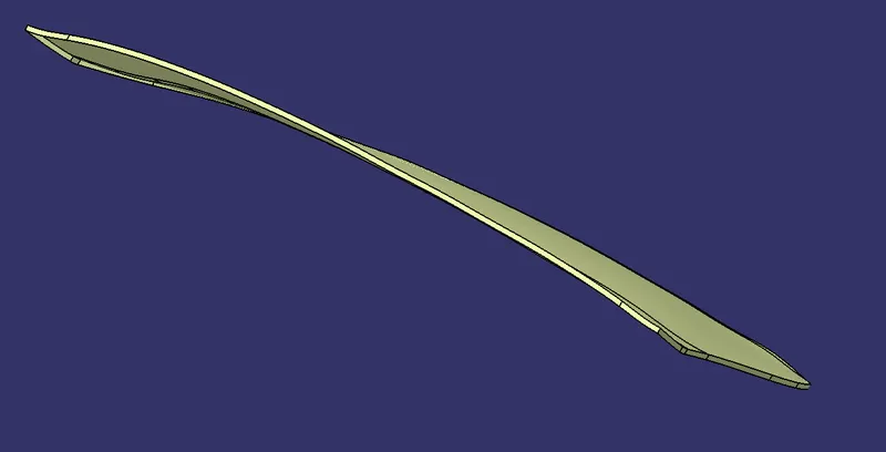
Then trim this join with B class surface to obtain closed surface.
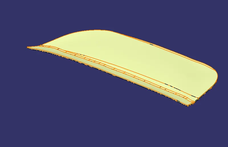
6. Creating solid feature by using closed surface.
Solid model is created from closed surface in the part workbench by using close surface command.
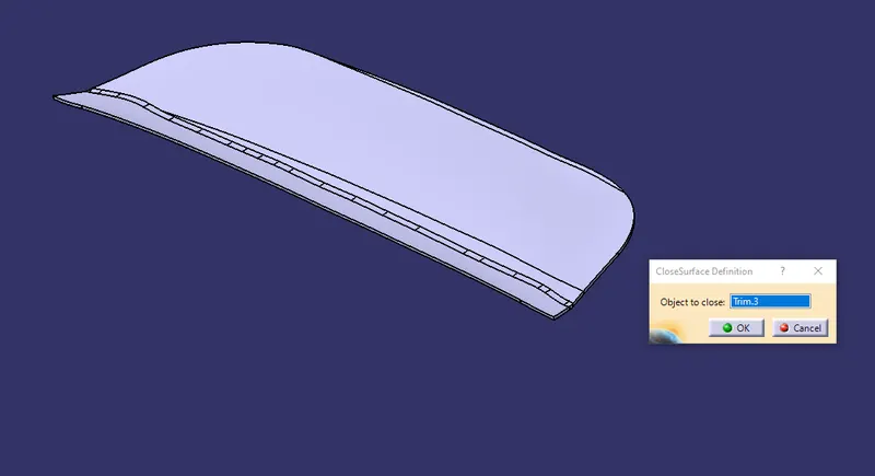
7. Creating 4 way & 2 way locators for fixing appliqué.
Now we have to fix this door appliqué with given door attachment. To fix this we need locators & heat stake.
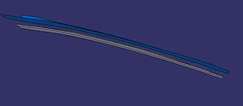
Assign 2 mm thickness to attachment surface in part workbench by thick surface command.
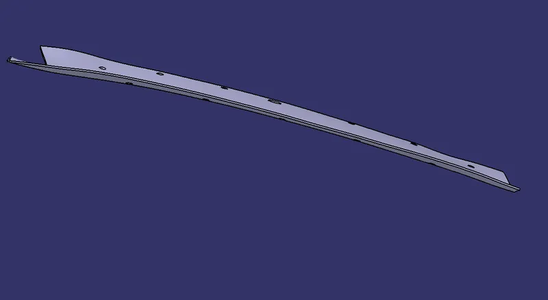
4 way & 2 way locators:
Create point on attachment surface at middle by using point command.
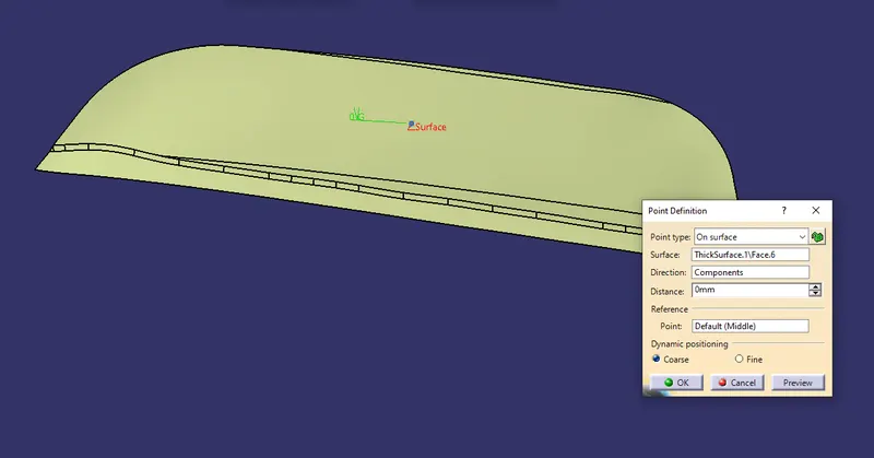
Create plane parallel to ZX plane & passing through centre point. This plane we used to create profile of locators.
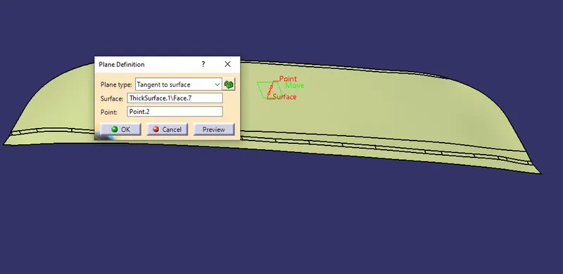
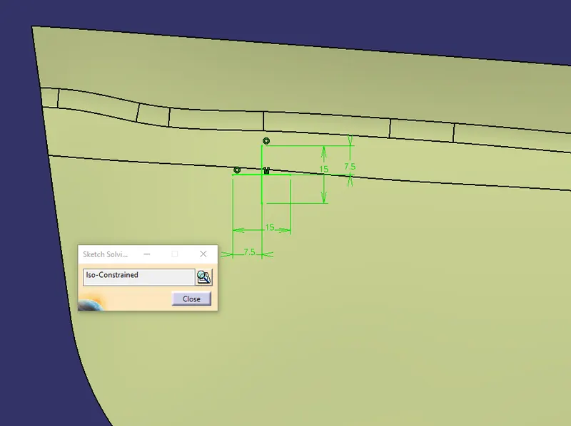
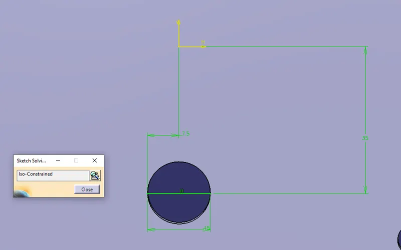
Make a profile of 4 way locator. Draw a positioned sketch on plane.
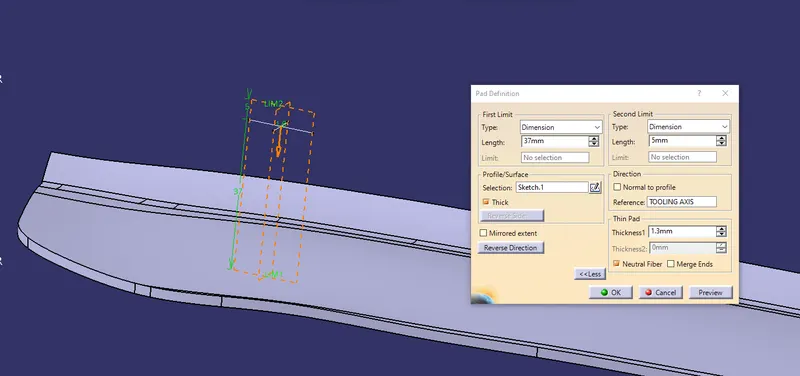
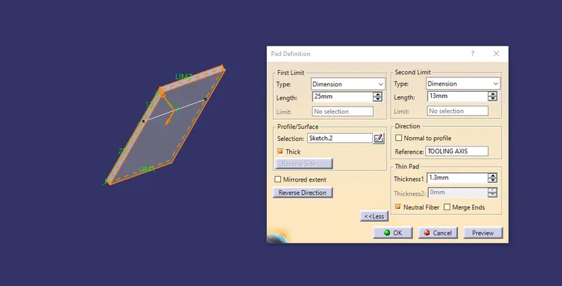
Pad this profile with thick feature & assign 1.3 mm thickness. Keep profile as neutral fiber while assigning thickness to get equal thickness on both sides.
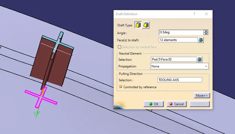
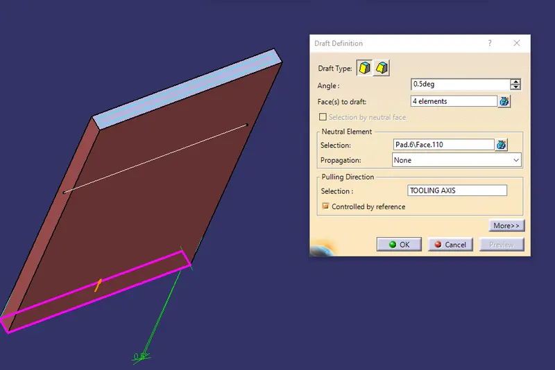
Add 0.5° draft to the faces of locator with pulling direction as tooling axis base as neutral element.
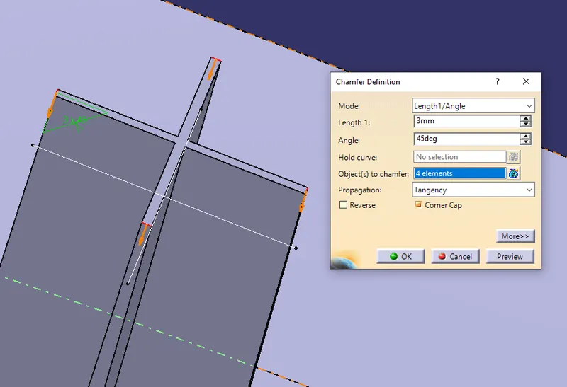
Give entry chamfer 3*45° & also give 3mm fillets to chamfered edges.
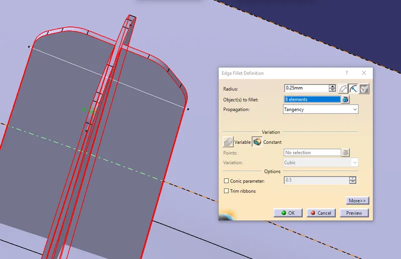
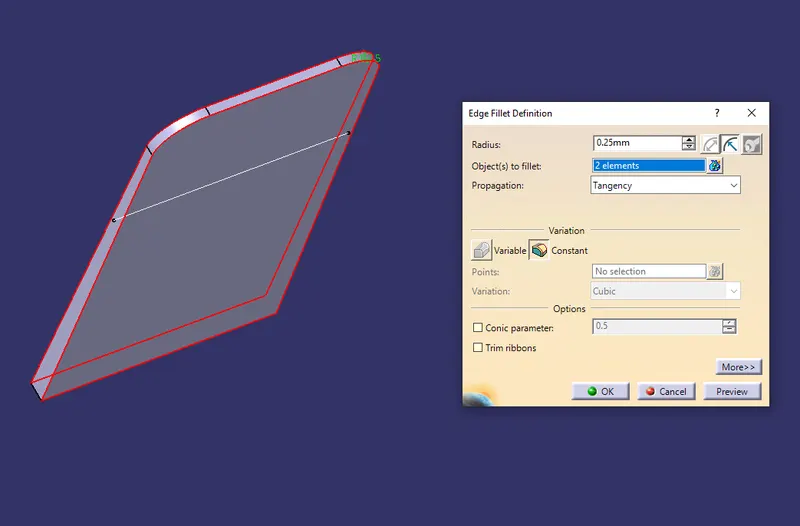
Give 0.25 mm fillet to all other edges.
Create copy of 4 way locator body in main part. Copy locator body & past special as result with link.
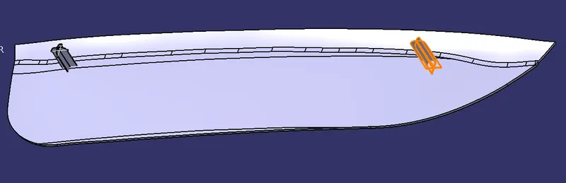
Translate copied body to desired position by use of coordinate within door appliqué area. Make sure both locators should be at same height.
Use Boolean operation. Union trim locator body with door appliqué.
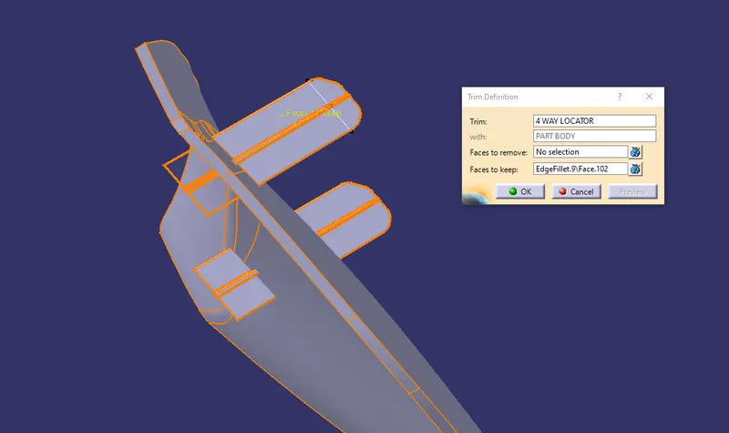
Similarly, follow above same procedure & create 2 way locator.
8. Creating heat stakes.
Extract class-A surface & offset it to 2.5mm. Extract the boundaries of class A surface with tangent continuity in two separate curves.
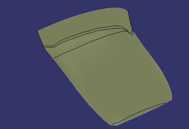
Create parallel curves for both boundaries at 15mm on respective surface.
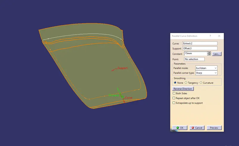
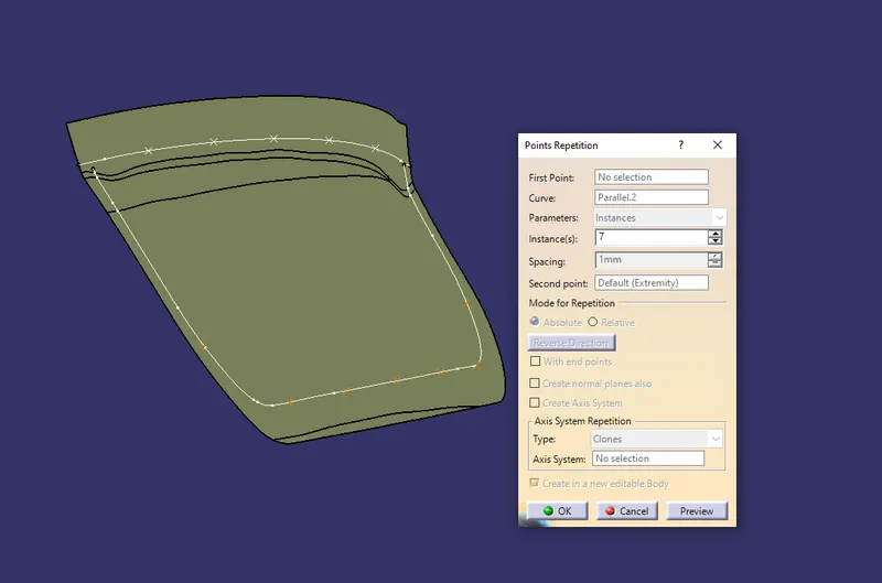
Create multiple points on two parallel curves by point & plane repetition command. These points represents centre of heat stakes. Make sure there is sufficient distance between heat stake & locator. To do this, adjust point’s instances accordingly.
Make a heat stake profile. Draw a positioned sketch at any one point.
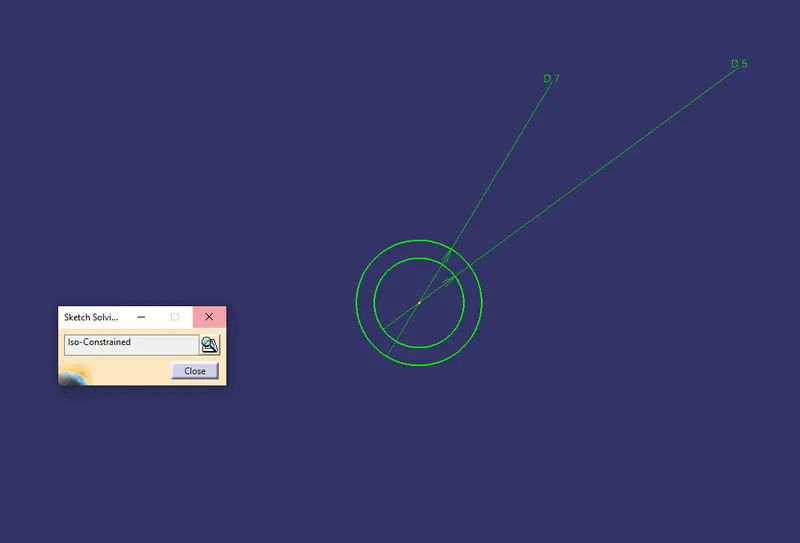
Pad this sketch & add 0.5° draft to faces. While padding make sure heat stake height should be less than locator height. Door appliqué must be located properly in place then it should be screwed.
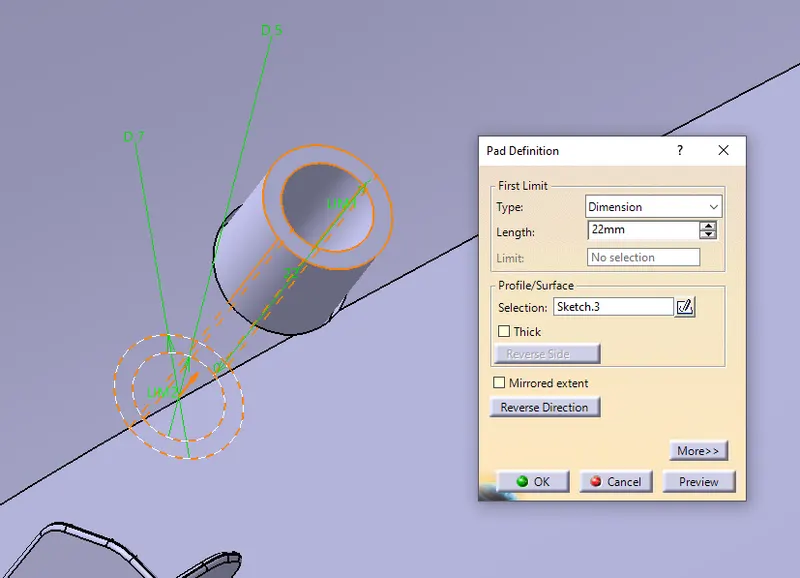
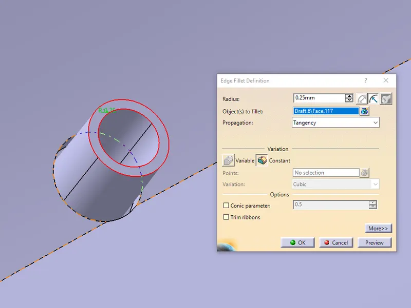
Provide 0.25 mm fillet at top outer edge of heat stake.
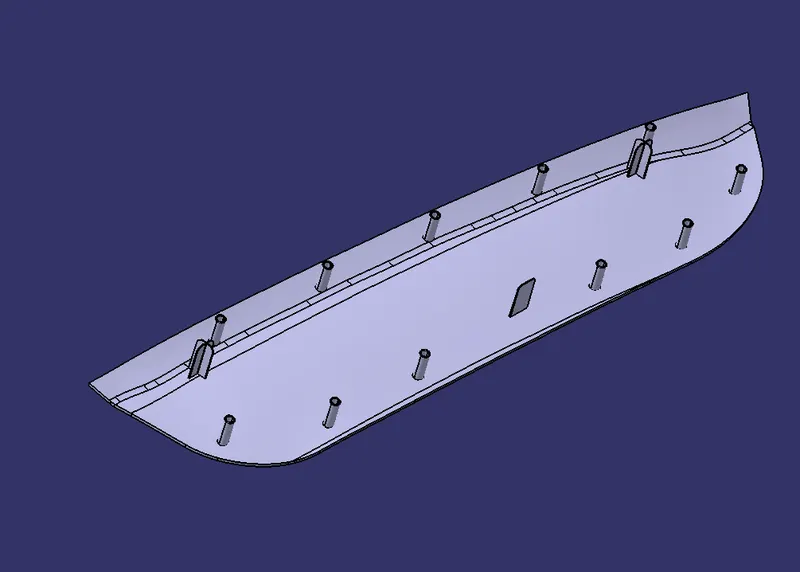
Now we have to make heat stake at every point on parallel curves. So, Copy this body & paste special as result with link in main part. Create no. of body equals no. of points.
Give point to point reference & translate heat stake to all created point.
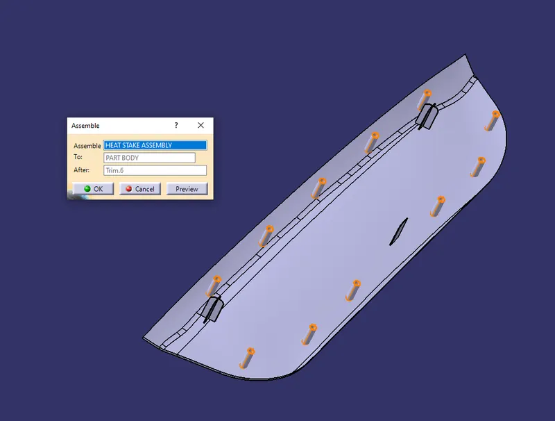
Assemble all heat stake body. Use Boolean operation & union trim all heat stakes with door appliqué.
Add 0.25mm fillet at base to all locators & heat stakes.
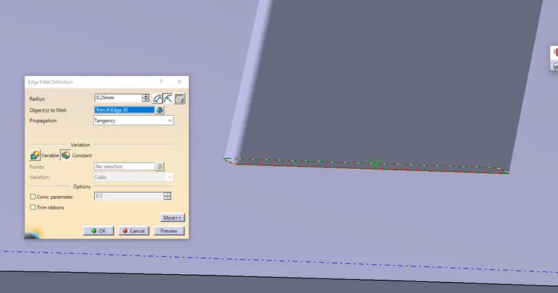
9. Creating clearance holes for locators & heat stakes on attachment part
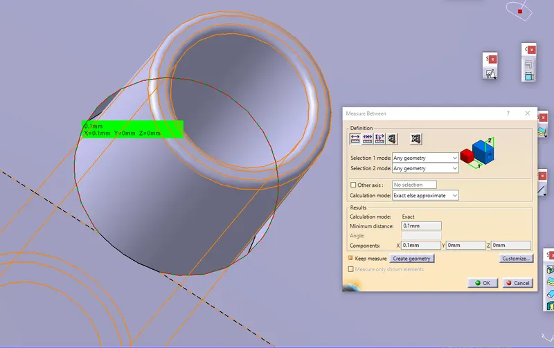
Door appliqué is ornamental part of door & to locate it with door we need clearance holes on counterpart. Provide 0.1mm clearance for locator & 0.5mm for heat stake.
Clearance hole for locator:
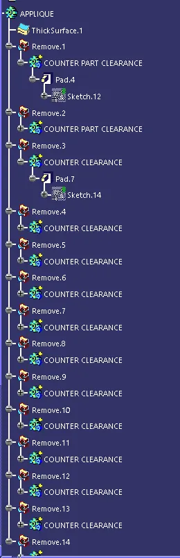
To create clearance hole make cylindrical body & remove it from attachment body.
Clearance hole should be created at same reference of locator. Use same locator sketch by copy & paste. Make other element as construction & draw a new circle at the centre.
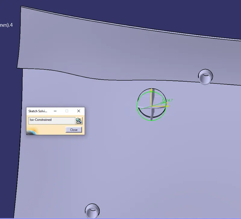
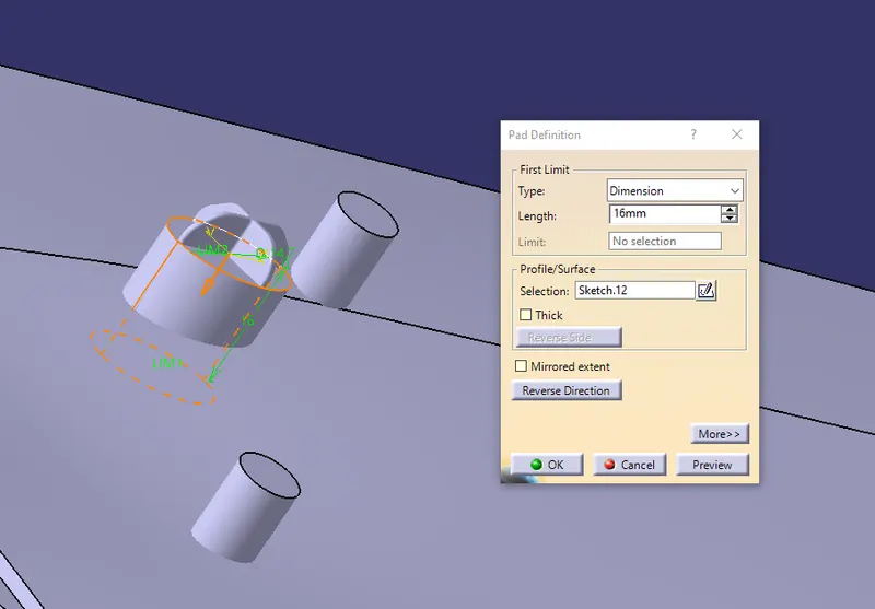
Use Boolean operation & remove form counterpart. Hence we get clearance hole for 4 way locator.
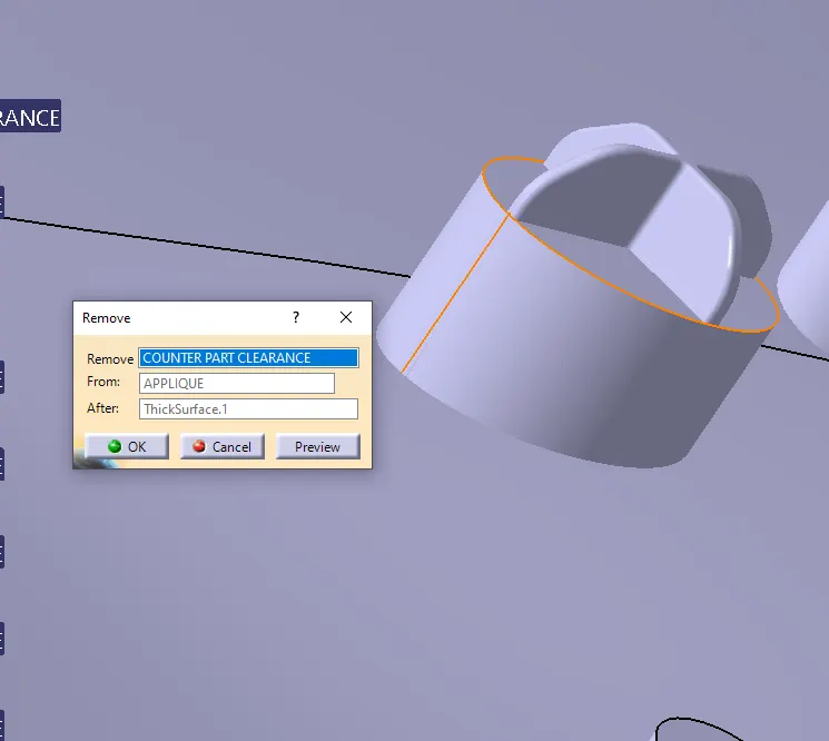
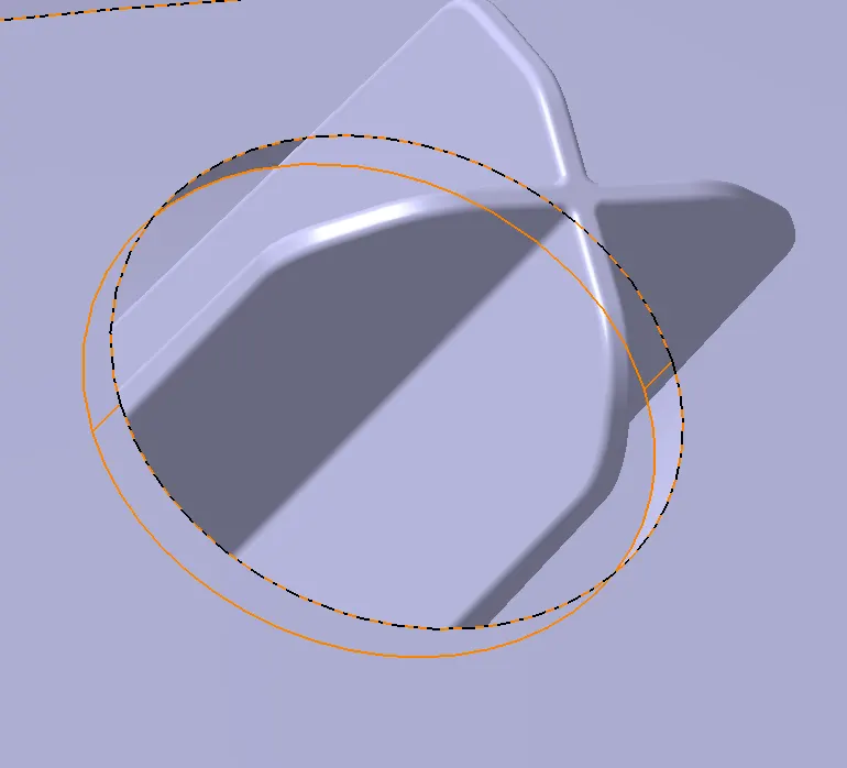
Create another instance by using copy & paste. Translate it to other locator position by using coordinate. Use Boolean operation to remove from counterpart.
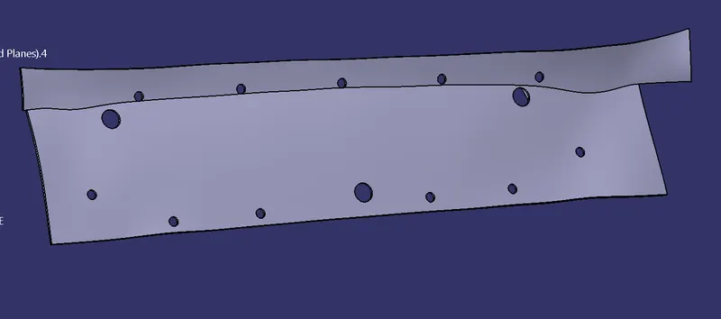
Ensure clearance it is around 0.1mm. If it is not around 0.1 then change pad value or modify sketch accordingly. A little deviation is accepted.
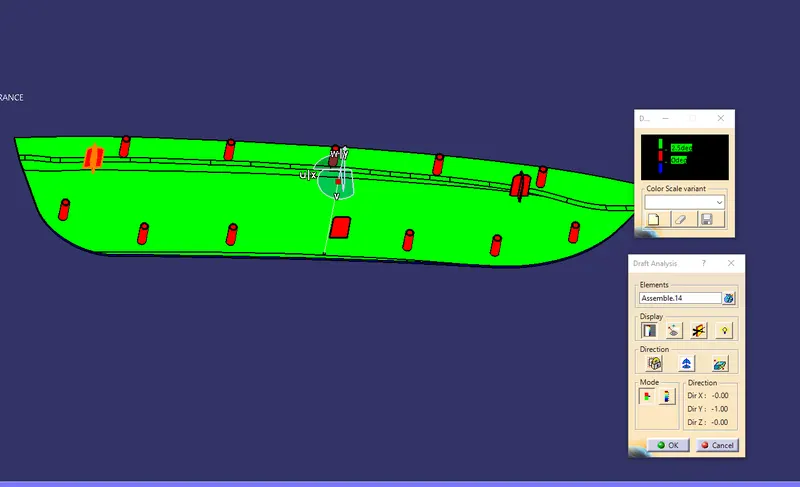
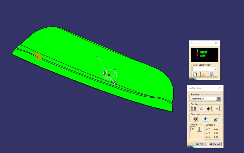
Images of the solid model with the proper color code of the draft angle in various orientations