Week 9 - Project 1 - Door Applique Design with Engineering Features
Report :-
To create the tooling axis, a point is required on the surface of the component, along which the draft analysis is to be done. A line is drawn, generally normal to that surface. This point is created by deducting the center of gravity of the component and extending it for the line.
The line is isolated, and is then used in the analysis for the drafting.
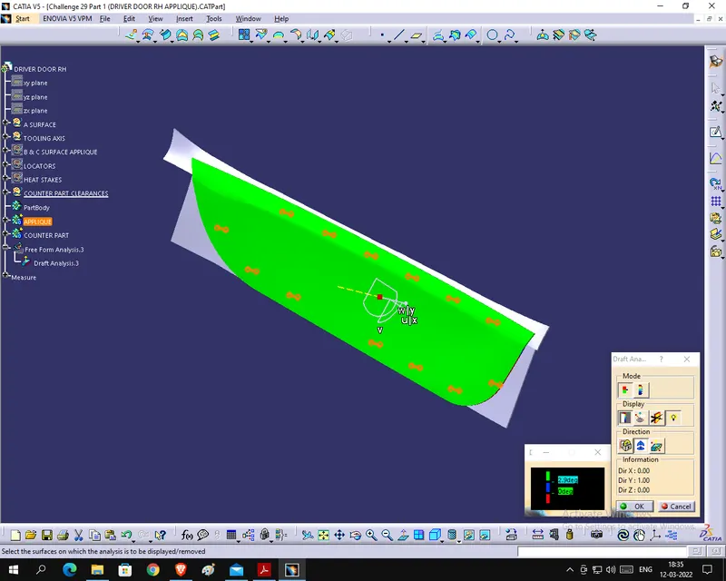
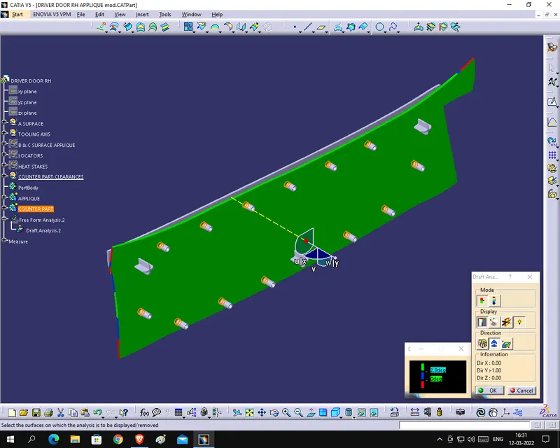
0 to 3 degree range of allowance for the drafting is provided while designing the component. A colour coding of red, blue and green is used to understand the drafting angle correctly and accurately.
If red the component or surface in that area cannot go further and has to be properly designed untill all the area turns green or at least blue, which is the acceptable angle of degree and falls in the range.
In the BISECTING METHOD of tooling axis creation, an intersection of the component is created. On this intersecting line, two lines are extended from the surface which looks the most protruding and easily ejectable form the mould after the solidification process. These lines are generally symmetrical in the opposite direction of the center of the intersecting lines.
A line is again created, which this time is the bisecting line between the two previously created lines and is isolated and named as the TOOLING AXIS,
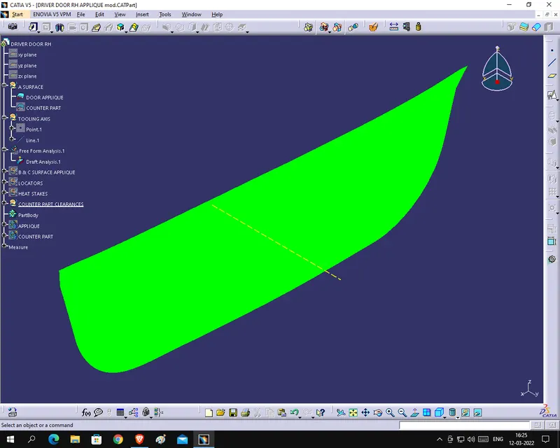
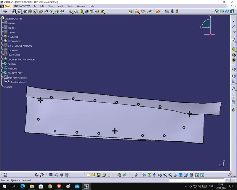
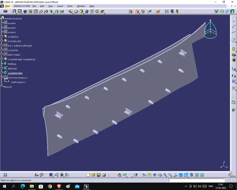
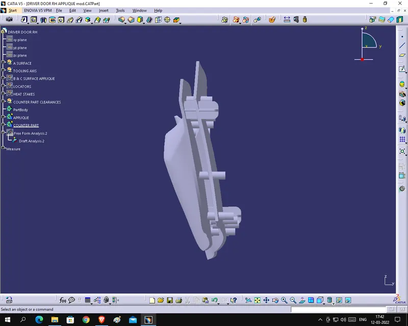
Draft analysis when done, the main axis of the design is aligned with the tooling axis and the analysis takes place or is done by the software, after whichas shown above the green or any other colour as per analysis is projected to indicate the analysis done.