Week 9 - Project 1 - Door Applique Design with Engineering Features
AIM : Create the Door Applique Plastic component through the given Class-A surface and perform the Draft analysis on the model also Create the Heat Stakes and the locators considering the design rules.
INTRODUCTION
Heat process used to join two or more parts out of which at least one is made of plastic, heat staking involves deforming the plastic material using heat and force at a set process time. The bond is made by partly de-forming the plastic part to fix the other. Therefore, the process makes it easy to bond metal to plastic, which is why it is commonly used in high volume/low cost applications like automotive, IT and consumer appliances.
The process of heat staking
Basically, the heat staking process can be broken down into four main steps:
- The thermode, with defined cavity, comes down on the stud;
- Force is then applied on the stud and once the required forces is achieved the heating process starts;
- The force together with the pre-set heat will then soften the stud and mould it into the required shape and at the same time fix the second part;
- Cool down, still under forces to below glass transition temperature and finally lift the thermode.
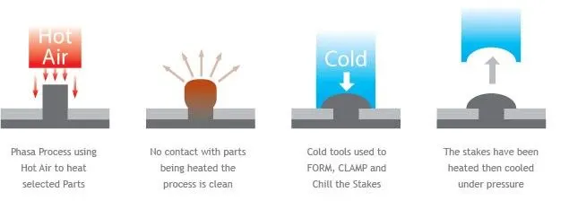
Benefits of heat staking
In addition, heat staking has many benefits. However, this depends upon the application, benefits include:
- Heat staking enables similar and dissimilar materials to be joined.
- Local heating ensures that there is no damage to adjacent materials.
- There are many heat stake shapes available through custom designed tools.
- No mechanical vibration.
- Very simple design guidelines are required for success.
Disadvantages of heat staking
Although proving extremely beneficial for many, heat staking has its drawbacks:
- If formers are too cold they will strain the stake causing stress, which may also impact breakages leading to failure.
- Temperature control is difficult to achieve with large multiple staking applications.
- The number of posts heat staked at one time is limited by the configuration design of the parts being assembled.
What Materials Are Best Suited For Thermal Press?
Heat staking technology is ideal for most native and blended thermoplastics on the market today, as well as the most robust glass and/or other-filled plastics. It produces high quality results when used with any of the following materials:
- Polycarbonate (PC)
- Polypropylene (PP)
- Polystyrene (PS)
- Acrylonitrile butadiene styrene (ABS)
- Nylons (GFN or Nylon6/6)
- Ultem (GFN or Nylon6/6)
2-WAY AND 4-WAY LOCATOR
4-way mean you prevent movement at 2 axis (+X, -X, +Y and -Y) on the plane. Generally you have cylindrical pin on the fixture and circular hole at workpiece part.
2-way mean you prevent movement only at 1 axis on the plane. And generally you have cylindrical pin on the fixture and slot hole at workpiece part.
Degree of freedom
The degree of freedom defines as the capability of a body to move. Consider a rectangular box, in space the box is capable of moving in twelve different directions (six rotational and six axial). Each direction of movement is counted as one degree of freedom. i.e. a body in space has twelve degree of freedom.
Above figure shows a body in space and its possible direction of movement. The body can move two directions along the each axis of three mutually perpendicular axes; also can rotate about this axis either clockwise or anticlockwise. There are twelve degree of freedom for a body in space.
In machining process, in order to attain specific results, the degree of freedom is constrained by using work holding devices.
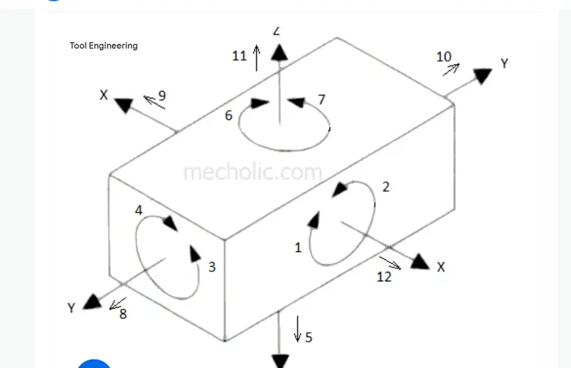
The Locating Process: Degrees of Freedom
In order to completely specify the position in space of a three-dimensional
object (such as the cube that’s shown), we refer to six coordinates:
- Translational position along the X-axis
- Translational position along the Y-axis
- Translational position along the Z-axis
- Rotational position about the X-axis
- Rotational position about the Y-axis
- Rotational position about the Z-axis
These six coordinates are known as the six degrees of freedom of a three-dimensional object. As the double-headed arrows indicate, the translational and rotational positions can vary in either direction with respect to each of the three axes.
To completely prevent movement, all six degrees of freedom must be restricted.
The Locating Process: 3-2-1 Method
We have two objectives when mounting a part in a fixture for machining:
1. Accurately position the part at the desired coordinates.
2. Restrict all six degrees of freedom so that the part cannot move.
A widely used method of accomplishing these two objectives uses the 3-2-1 principle, so-called because it entails three steps that employ three, then two, then one fixed points of known location. Since that adds up to six fixed points, it’s also known as the six point method.
In the three steps of the 3-2-1 method, three mutually perpendicular planes, called datum planes, are introduced, one at each step. These three planes define the workpiece position, and together with opposing clamping forces fully constrain the part. Let’s take a look at the details of the 3-2-1 method.
First Plane
Geometry tells us that three points are required to define a plane. This is the "3" in 3-2-1. So, three specific points are used to define the first plane. Fewer than three points cannot define a plane, and in the real world dimensional tolerances mean that four or more points will not be coplanar. A real-world, less than ideally perfect part placed on four or more reference points will, in fact, rest on only three of the points due to its less than perfect surface. Different parts may rest on different combinations of three points, resulting in variation between finished parts. A stool can be used to illustrate this concept. A two-legged stool would certainly be unstable. A three-legged stool sits rock-solid. A four-legged stool is often found to rock. In the illustration, a three dimensional part, represented by a cube, is placed on a datum plane defined by three support points. The part’s six degrees of freedom have now been reduced to three. It can still move along the X or Y axes, and it can still be rotated about the Z axis. (The part cannot move along the Z axis because it is held against the plane by clamping force.
Second Plane
A second plane, if it is perpendicular to the first, can be defined by two points, the "2" in 3-2-1. The part is now constrained to one degree of freedom: movement along the Y axis. (The part cannot move along the X or Z axes because it is held against the planes by clamping force.)
Third Plane
A third plane, if it is perpendicular to both of the first two planes, can be defined by one point, the "1" in 3-2-1. The part is now entirely constrained. It cannot move along or rotate about the X, Y, or Z axes. (Remember that the part is held against each of the three planes by clamping force.)
STEP FOLLOWED
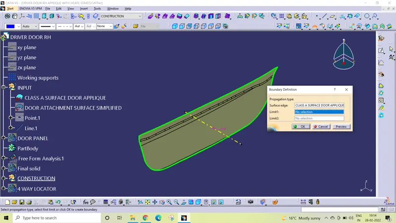
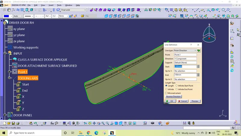
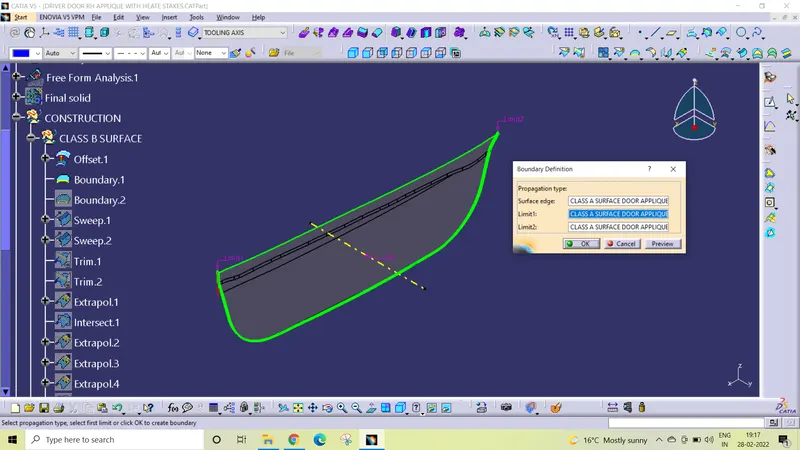
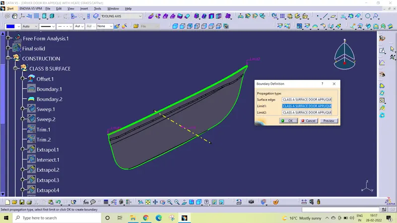
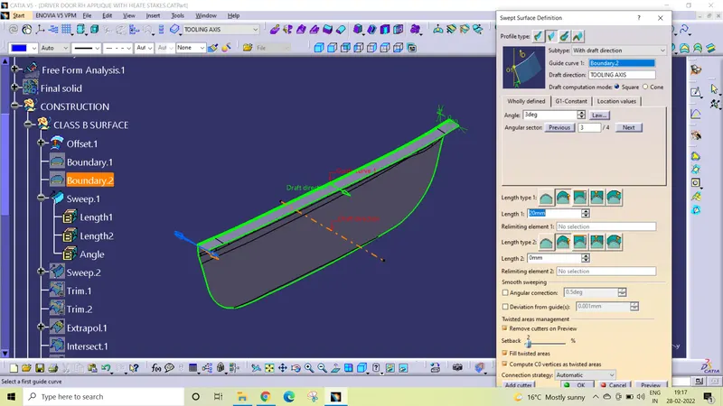
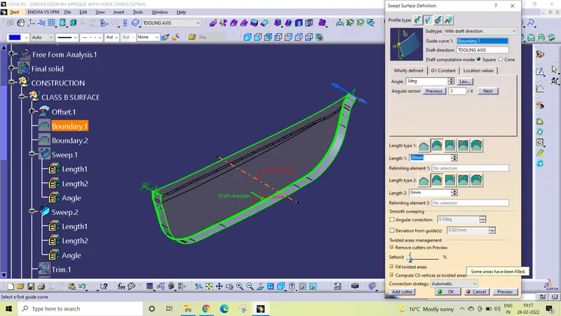
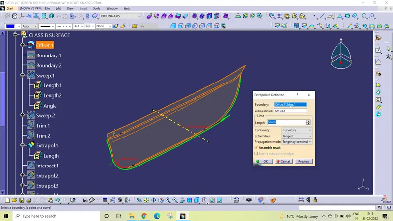
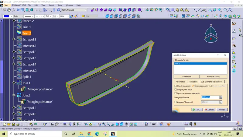
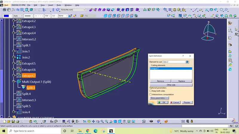
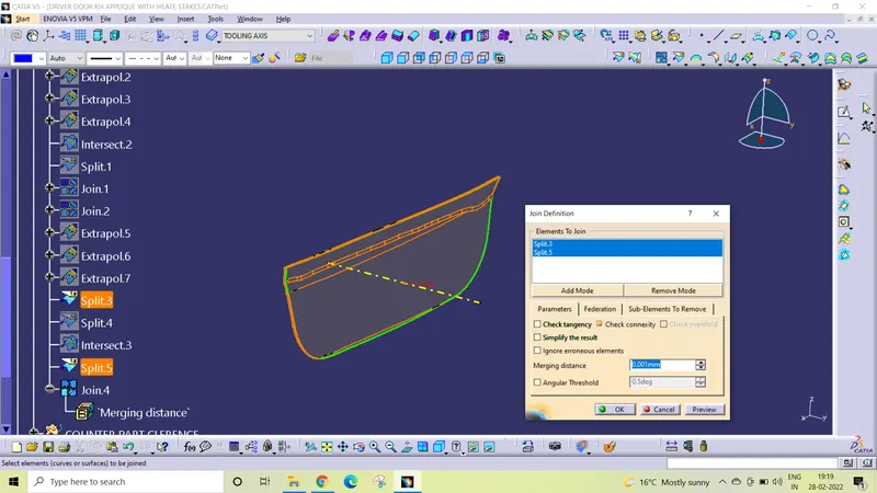
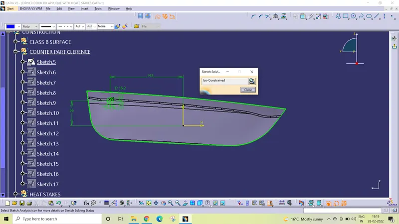
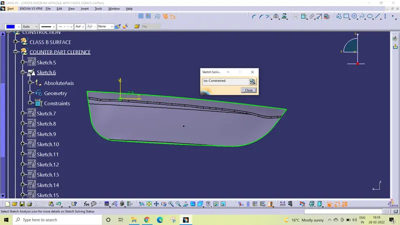
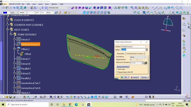
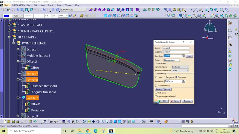
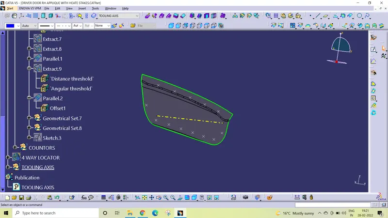
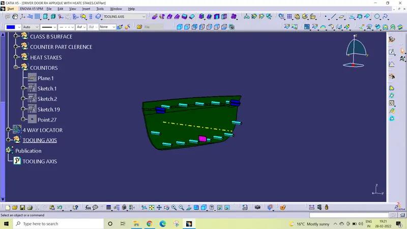
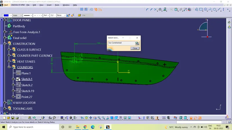
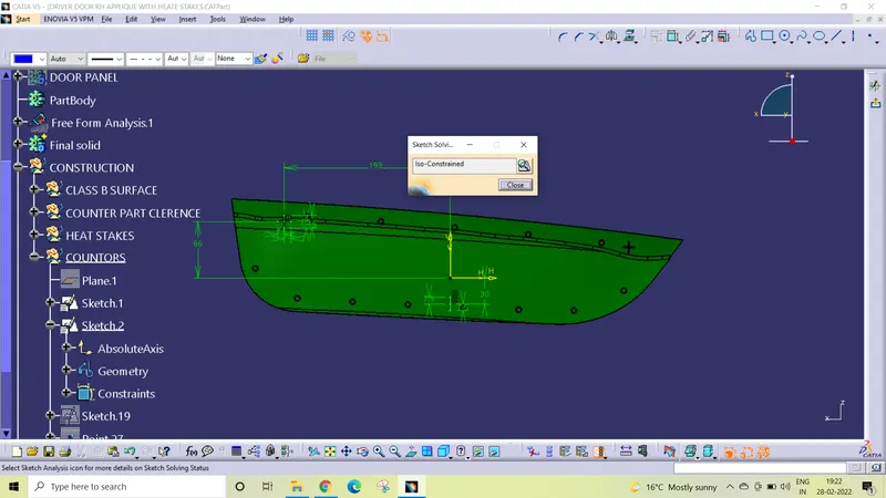
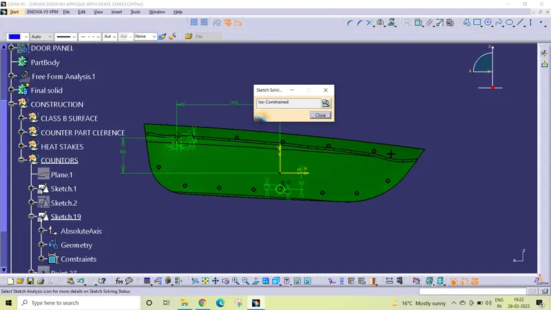
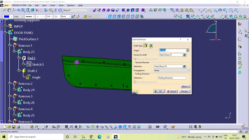
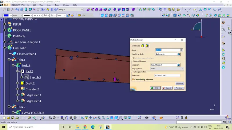
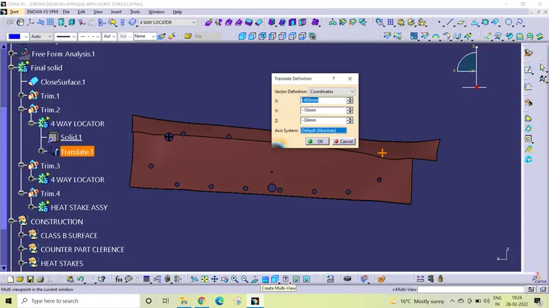
DRAFT ANALYSIS
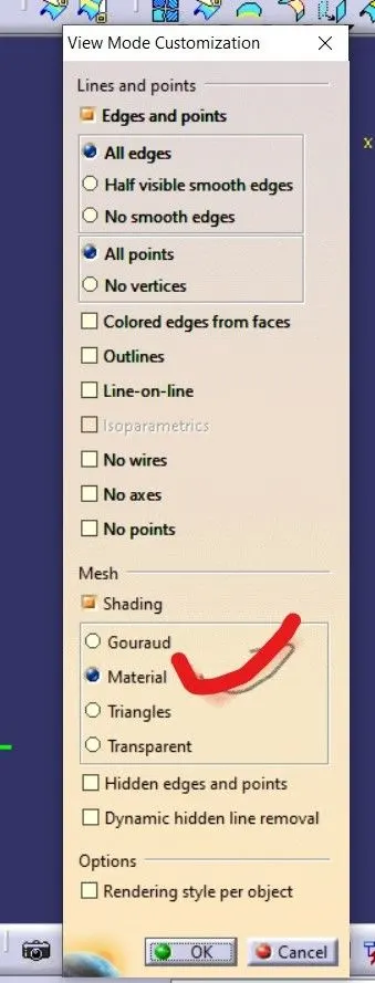
To perform the draft analysis on the bracket model, first set the view parameters to material mode.
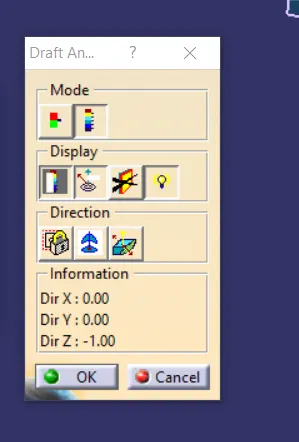
Then go to menu bar select insert analysis feature draft analysis
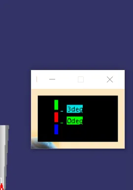
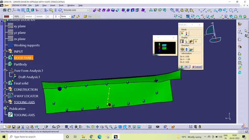
To give the draft direction, use compass and align Z axis of it with the final tooling axis for the Door Applique Plastic component. Once it is properly aligned, lock the draft direction. Select the Door Applique Plastic component and it will show us the current draft angle of the model, set the draft value 3 degree under the color scale variant and press ok.
Using the draft analysis option we can perform draft analysis on Class A surface and final part of Door Applique Plastic component.
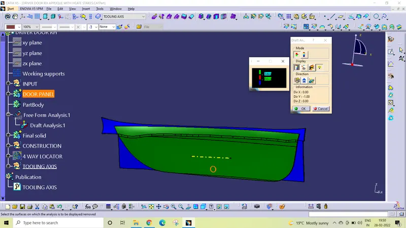
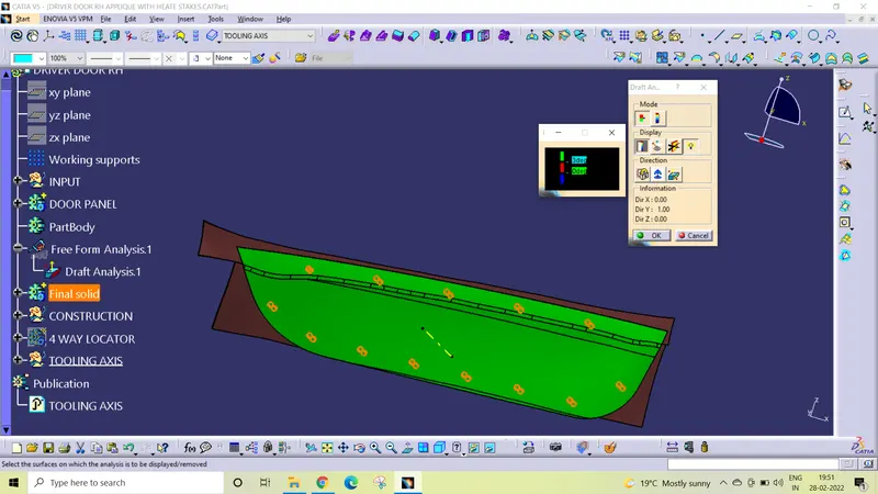
ISO VIWS
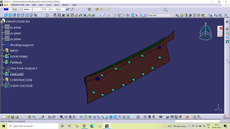
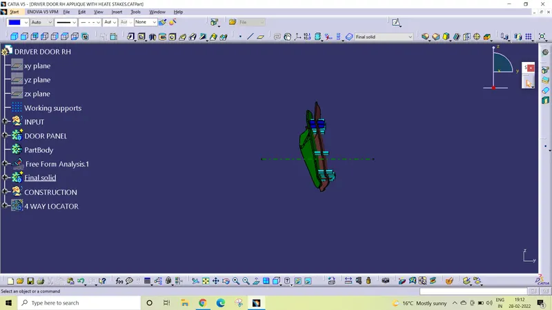
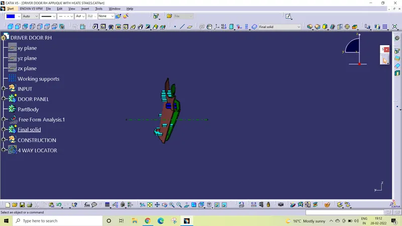
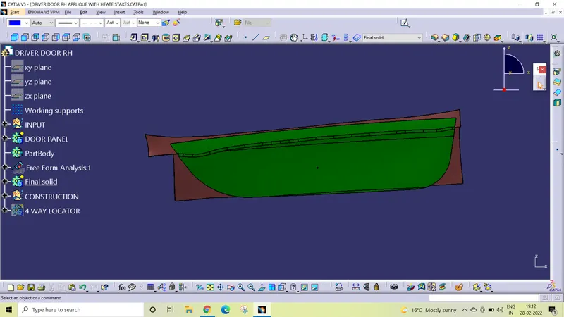
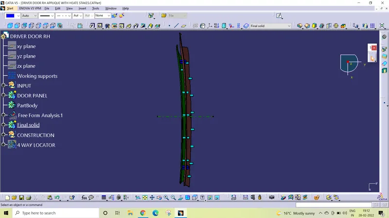
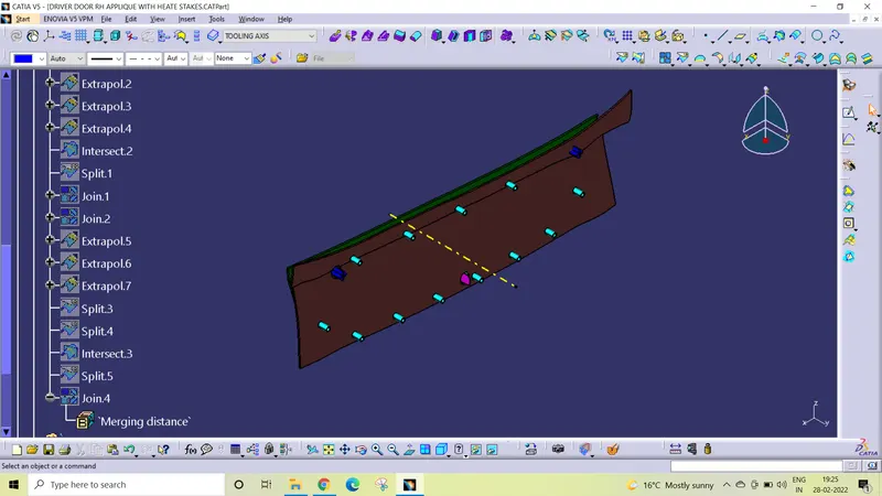
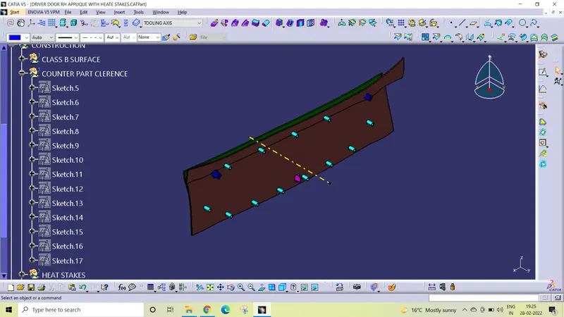
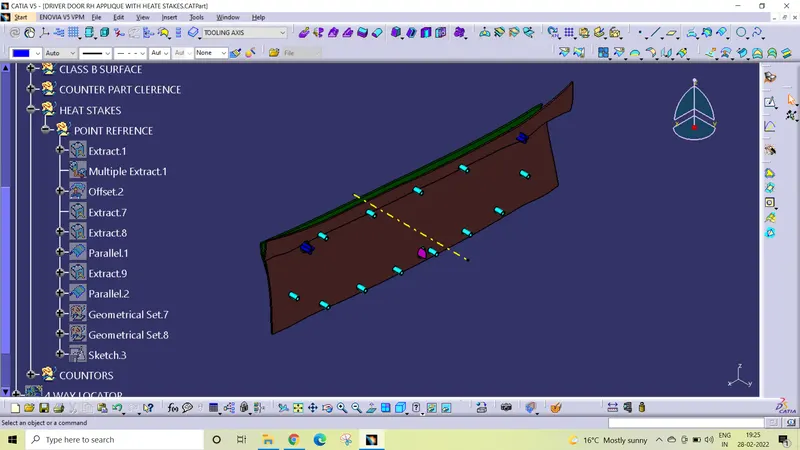
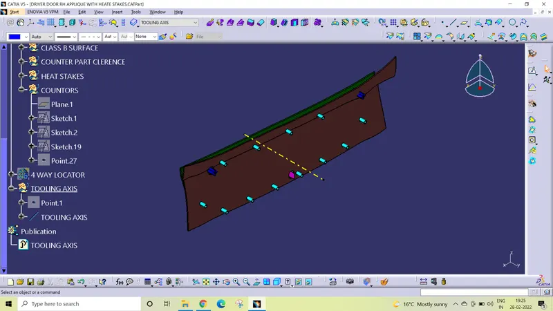
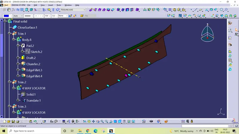
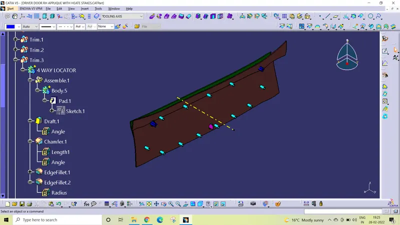
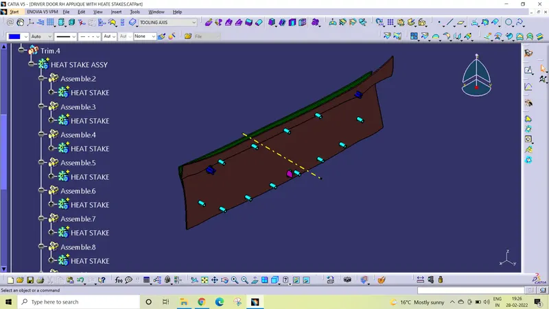
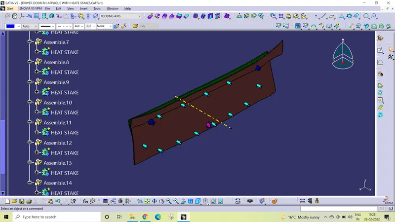
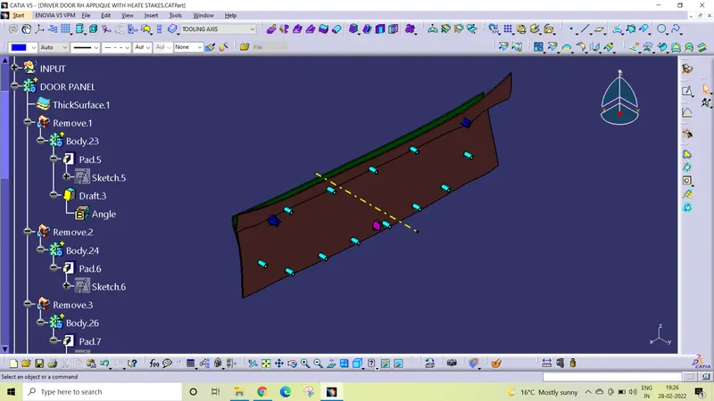
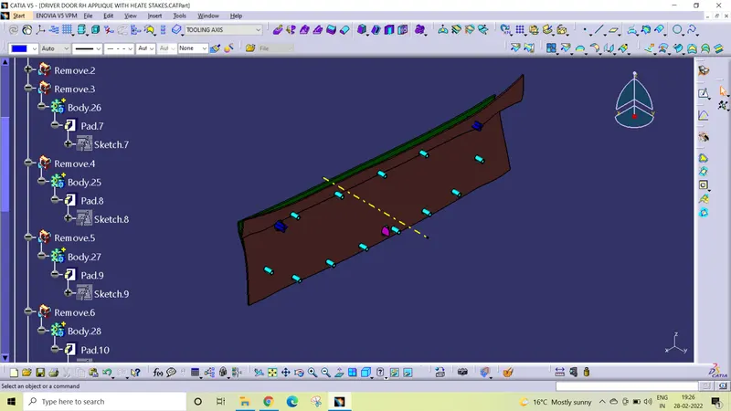
screenshots OF TREE
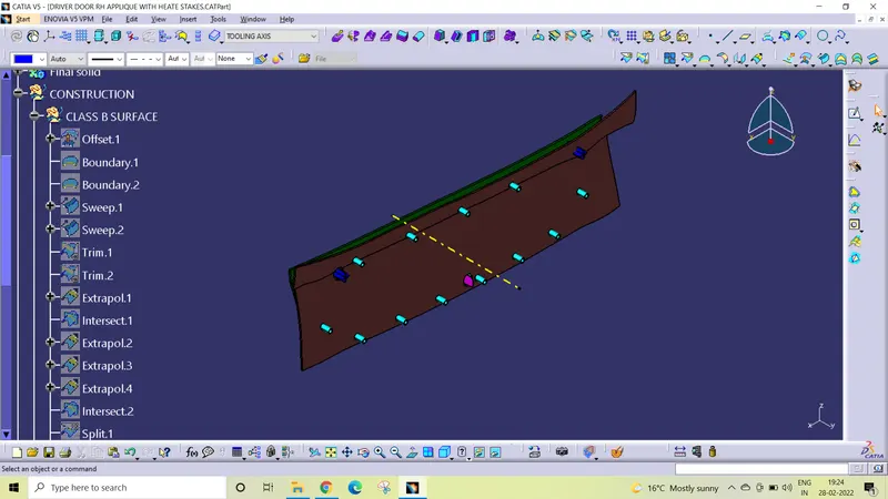
Conclusion
Door Applique Plastic component using Class A surface have been successfully created and draft analysis have also been performed for the same.