Week 9 - Project 1 - Door Applique Design with Engineering Features
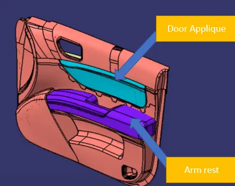
Introduction
Having easier ejection from the mold may seem like a minor concern, but draft is crucial to manufacturing parts that meet your quality standard. Without draft, major problems can arise in the injection molding process that increase the time and cost of production.
When no draft is designed into the part, problems can come from friction and vacuums. These issues can damage both your part and even your mold in extreme cases. These problems are a direct result of having insufficient draft. Because plastic shrinks as it cools, portions of the part may pull away from the mold while others grip the core. If there is no draft angle that allows a simple push from the ejector pins to pop the part out of the mold, the part’s surfaces will often drag along the mold as it is being ejected. This friction between the two surfaces can cause scratches or gouges in your part and affect the appearance. This is particularly troublesome if your part is being molded with a surface finish or texture. The friction will scrape away texture and leave you with many rejected parts.

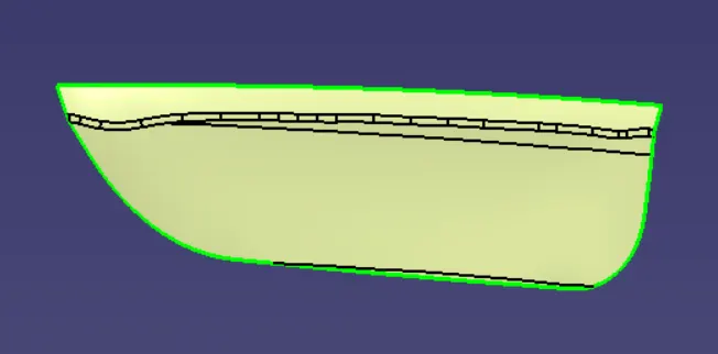
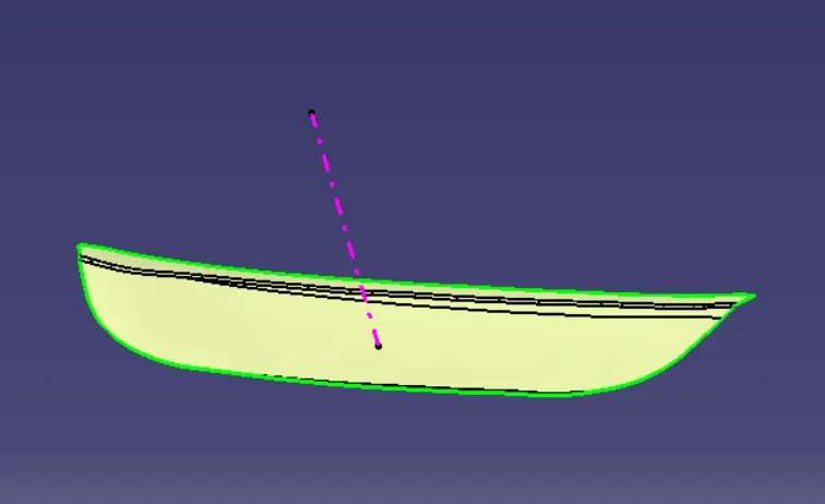
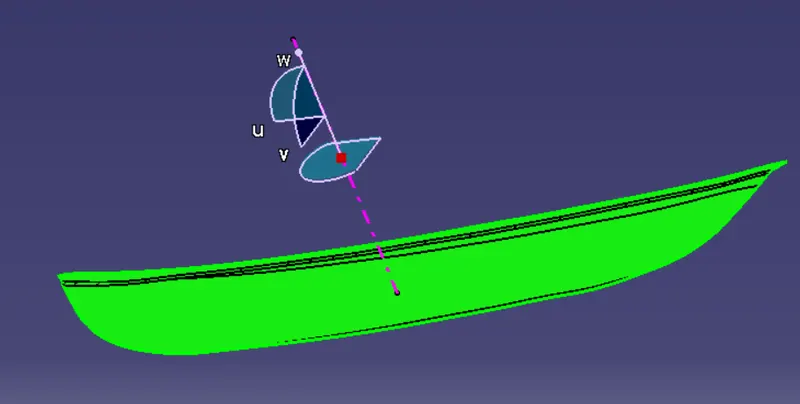
Designing the class B surface from the given class A surface is the next step to be followed
- As the fillets gives problem during the thickening we extract the required surface and offset all the extracted surfaces towards the class B region by 2.5mm and trim them and provide the necessary fillets following the rule(Radius of the fillet of class A surface) ±(the offset value) to get the class B surface
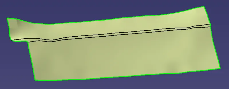
Class C surface
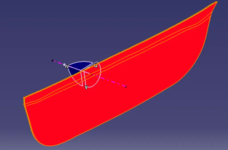
Class C surface are once which lies between the Class A and B surface . while creating the class C surface we have provided the draft greater than 3 degree in such a way that the parting line lies at the B surface. And this is done to prevent flash on the Class A surface.
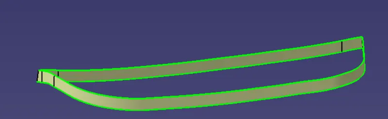
Class A , B , C surface after the final trim
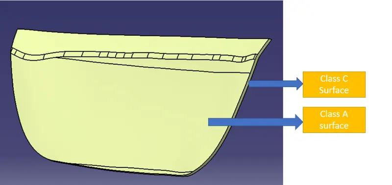
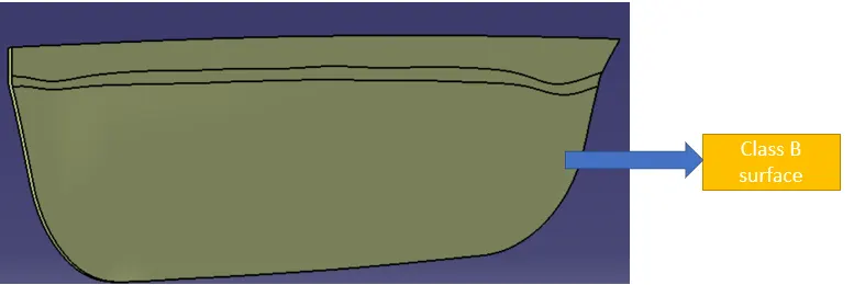
Tree Structure
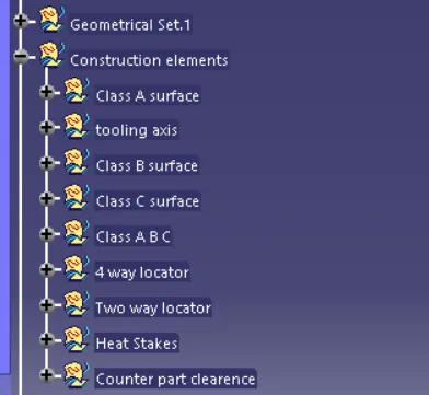
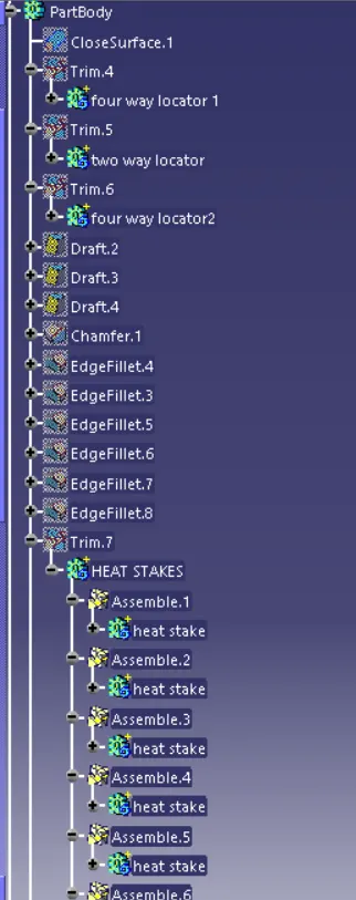
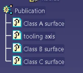
Publication is done as it is easy to access the tooling axis and the Class A surface
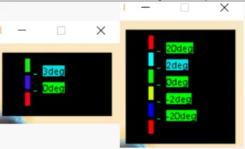
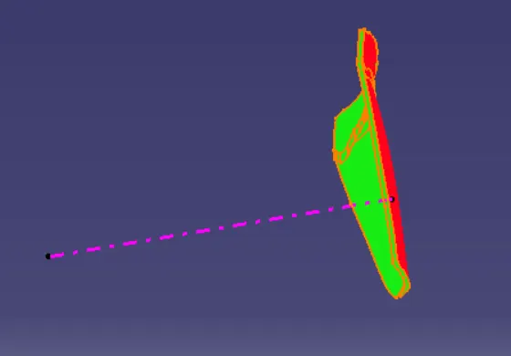
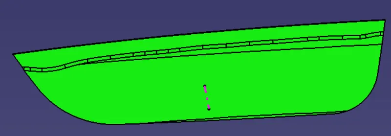
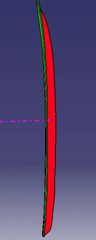
Colour scale which indiactes the degrees at sepecific location
Engineering Features
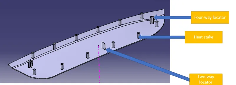
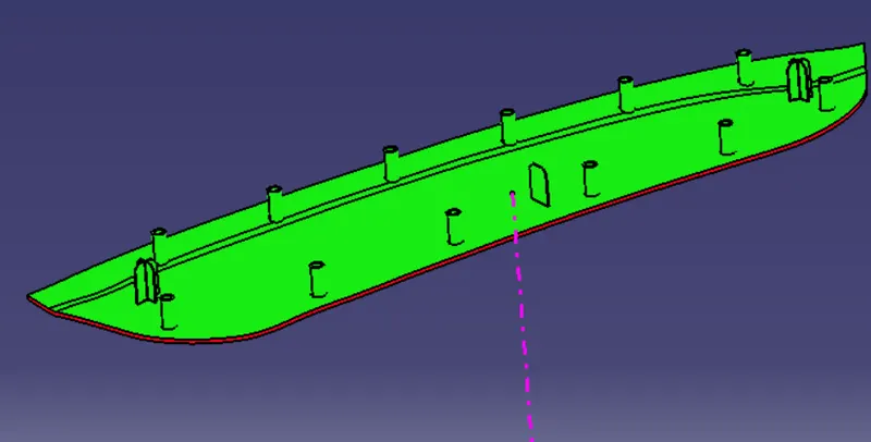
4 way locator and two way locator
4-way mean you prevent movement at 2 axis (+X, -X, +Y and -Y) or in other words 4 degrees of freedom on the plane. 2-way mean you prevent movement only at 1 axis or in other words 2 degrees of freedom on the plane.
The 3-2-1 principle states that the six locators are sufficient to restrict the required degree of freedom of any work piece
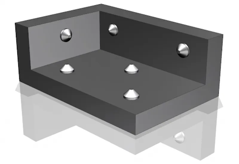
Any part which has a welding or machining process while having a fixed 12 degrees of freedom.
- Translation Movement along X Axis.
- Translation Movement along Y Axis
- Translation Movement along Z Axis
- Rotational Movement along X Axis
- Rotational Movement along Y Axis
- Rotational Movement along Z Axis
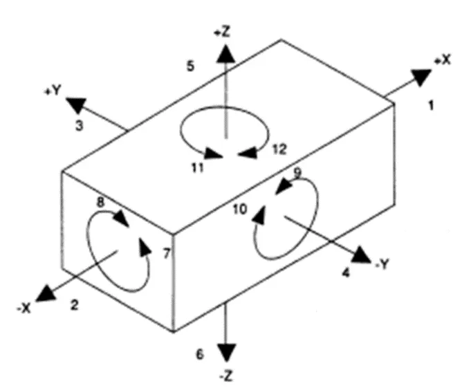
While fixing we arrest 11 degrees of freedom, and the remaining 1 degree of freedom is in the fixing direction
Heat stakes
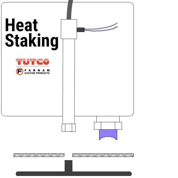
Applications using heat staking
Applications include:
- Attaching metal grilles and screens to plastic frames
- Automotive panel
- Automotive dash mat
- Mobile phone assembly machines
- Antennas in handheld devices
Benefits of heat staking
- Heat staking enables similar and dissimilar materials to be joined.
- Local heating ensures that there is no damage to adjacent materials.
- There are many heat stake shapes available through custom designed tools.
- No mechanical vibration.
- Very simple design guidelines are required for success.
Disadvantages of heat staking
Although proving extremely beneficial for many, heat staking has its drawbacks:
- If formers are too cold they will strain the stake causing stress, which may also impact breakages leading to failure.
- Temperature control is difficult to achieve with large multiple staking applications.
- The number of posts heat staked at one time is limited by the configuration design of the parts being assembled.
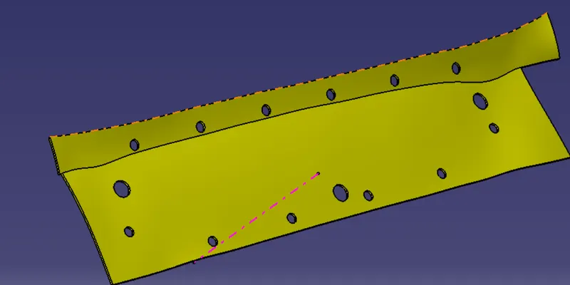
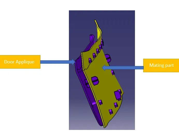
Once done with the design of the engineering features the next step is to design the clearence in the mating surface
Draft Analysis of the engineering features
Conclusion
The Door applique's class B and C surface was designed for the given class A surface successfully alonng with engineering features