Week 9 - Project 1 - Door Applique Design with Engineering Features
AIM-
Create the Door Applique Plastic component through the given Class-A surface. To begin with, the tooling axis for the given Class-A Surface should be created meeting the requirements of the draft angle and at the end perform the Draft analysis on the model.
Create the Heat Stakes and the locators considering the design rules mentioned in the video for the door applique.
INPUT-
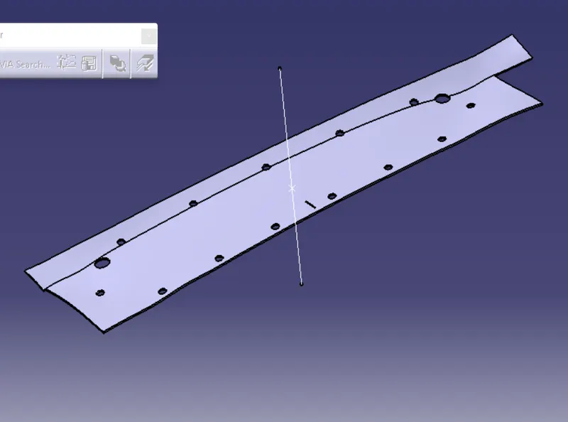
CLASS A SURFACE
DOOR ATTACHMENT SURFACE MODIFIED
STEPS OF DESIGN
CLASS A surface check the all boundary merged
and its check draft analysis in on direction
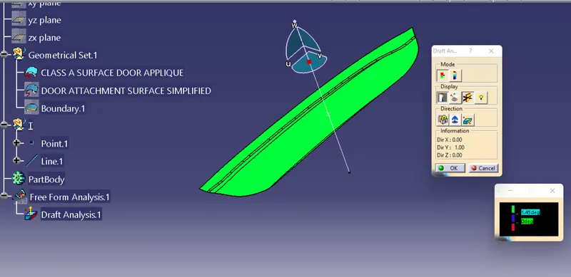
create a co-ordinate(0,0,0) on surface a point
create a tooling axis for crateing C SUFACE
offfset A SURFACE 2.5 MM create B SURFACE
IST of all select boundary limit one point to another point
and extrapolate this surface
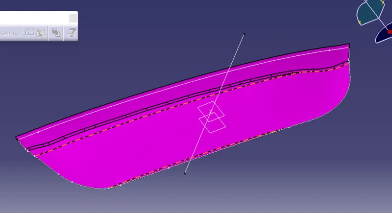
class A & B SURFACE
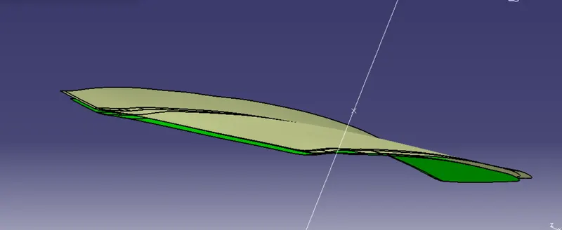
now create C SUFACE
create a boundary line sweep this boundary line 3 degree angle of draft
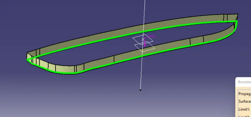
JOIN THE CLASS A & C SUFACE
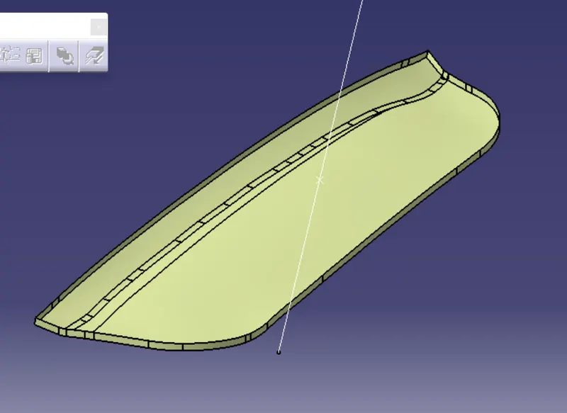
TRIM THE JOIN SURFACE & CLASS B SURFACE
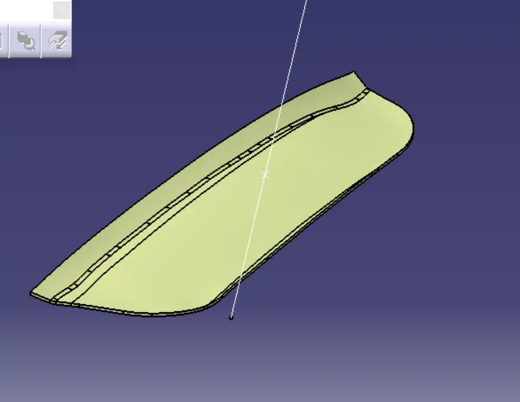
and solid it
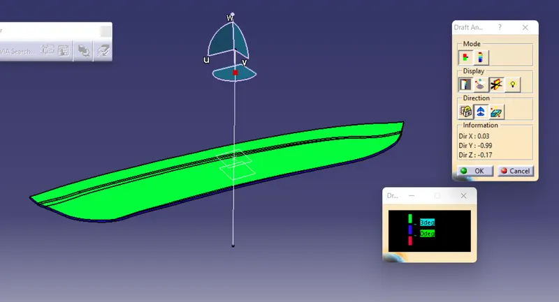
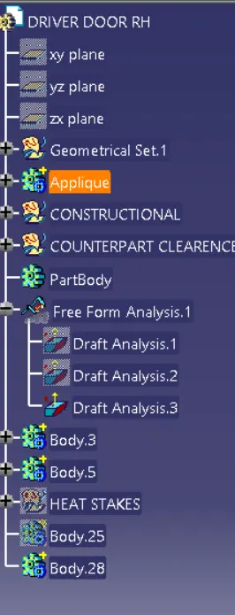
draft analysis
CREATE FOUR WAY & TWO WAY LOCATOR
MAKE a sketch for 4 way locator on one side of door appalique suface plane
pad it & draft angle .5 degree and its entry chamfer 3 x 45 degree
all edge are fillet
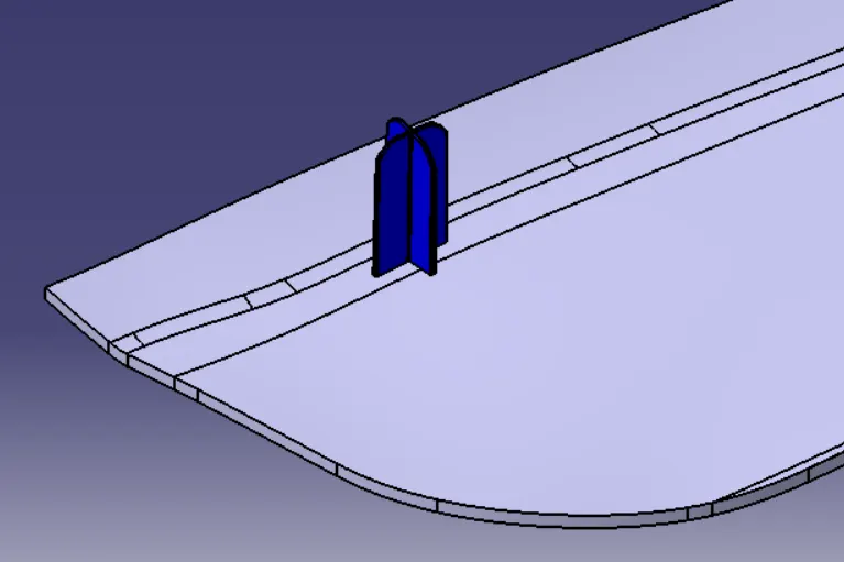
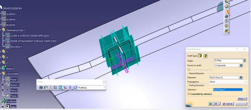
now make same lockter another side of appalique surafce
copy & paste with special link and translate this surface
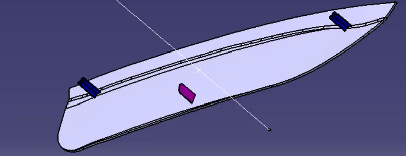
TWO WAY locator on another side as to four way locator
but draft analysis on locating tooling axis on door attachment surface
HEAT STAKES
Heat staking also known as thermoplastic staking is the process of joining two dissimilar materials together. In heat staking we use local heating and cooling to raise the temperature of plastic components and allow plastic reforming to be carried out. This reforming can be used in a wide variety of applications
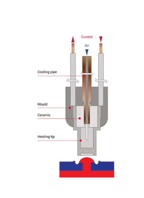
Heat stakes
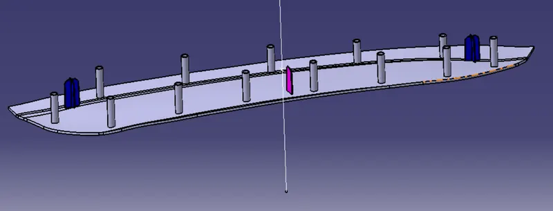
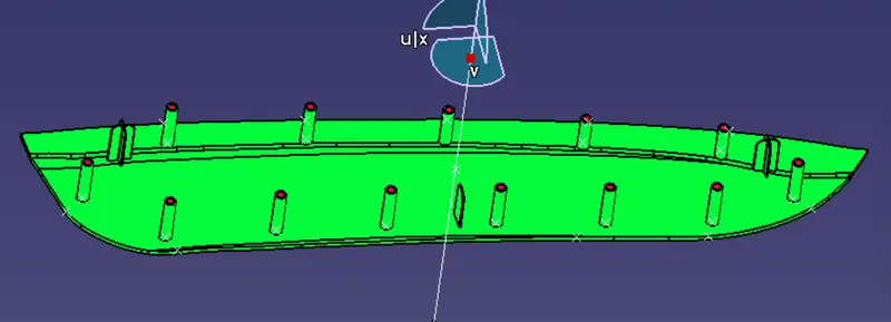
Then for creating the heat stakes on the door applique we first have to decide the points where the heat stakes would be placed. So we extract the class A surface and the edges and then use the parallel curve to offset the curve to 15mm which will act as path for the points to be placed. Then using point and plane repetition tool we make the points around the curve. DRAFT IT .5 DEGREE
Then we just copy the feature and then paste it using 'As result with link' and then translate it to other point. We repeat this process till all the heat stakes are placed at the points.
Then we use union trim to trim all the heat stakes with the door oblique part component.
Counter part clearance
We first use the thick surface tool to thicken the door attachment surface.
Since the features which we made protrudes through the door attachment we have to make a clarence for them. For this we make a hole in the door attachment. For the locators we take in the sketch of the locators as the reference and then draw a circle around it to as to give a clearance of 0.5mm around it. So we use pad tool for the circle and then remove it with respect to the part body for door attachment.
For the clearance for the heat stakes also we follow the same procedure.
DRAFT ANALYSIS
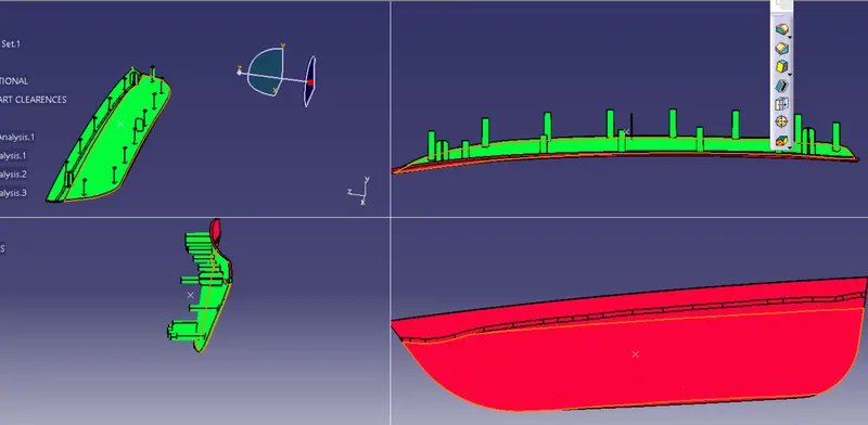
Draft analysis -
Before drafting we have to make sure that in the view mode it is selected to the materials.
After selecting the feature draft analysis tool we drag the compass from its position to the tool axis. Then lock the compass. After that select anywhere on the component and it will give you the result.
We change the minimum draft for the component to 0.45°.
Door applique
RESULT
LEARN about four way locator and heat stakes design & make this feauture in plastic component