Week 9 - Project 1 - Door Applique Design with Engineering Features
Aim:
- To design the Door Applique with engineering features such as Heat stakes and Locators, given CLASS A surface as input and also to perform Draft Analysis on the final 3D CAD model.
OBJECTIVES:
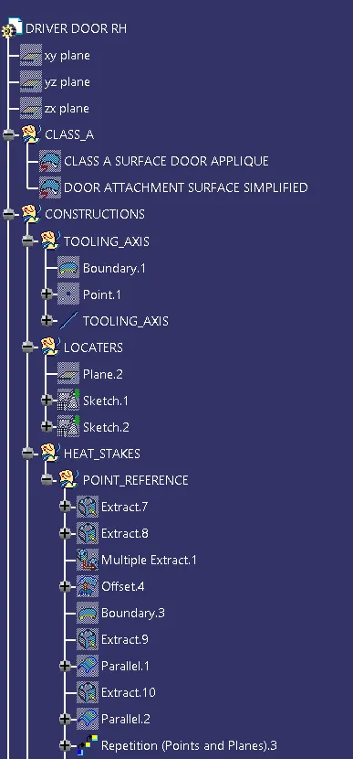
- The tooling axis for the given Class-A Surface should be created to meet the requirements of the draft angle
- Create the door applique plastic component through the given Class-A surface.
- Perform the Draft analysis on the model
- Create the Heat Stakes and the locators considering the design rules.
TOOLING AXIS:
- The tooling direction is used to find the direction in which the part is ejected out of the mold. The draft on the part should be positive in order to manufacture the part easily. The draft angle should be positive with respect to the tooling direction.
- Here the Y direction gives the proper view for the tooling axis.
- Now, we know the know Y direction is from where the tooling axis is going to lie but we don't know the direction for the axis.
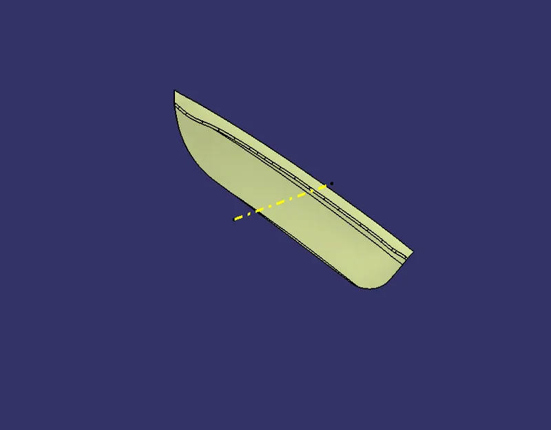
- So, the base is extracted and the point is created at the O coordinate (center of the surface).
- Then at this point, a line or axis is created in the Y direction.
2 WAY AND 4 WAY LOCATORS:
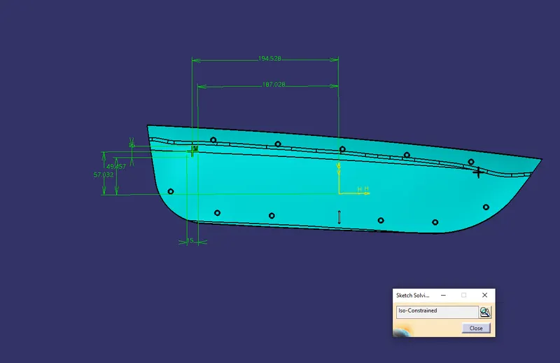
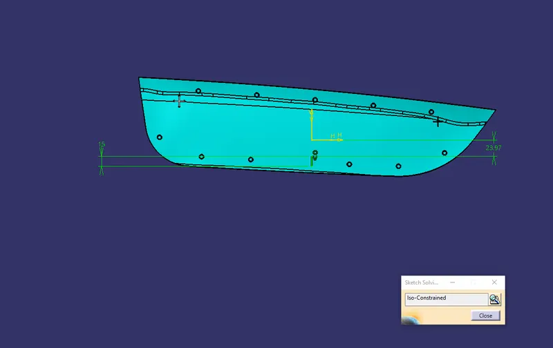
- To create 4 Way locators, the ribs should be created intersecting with each other.
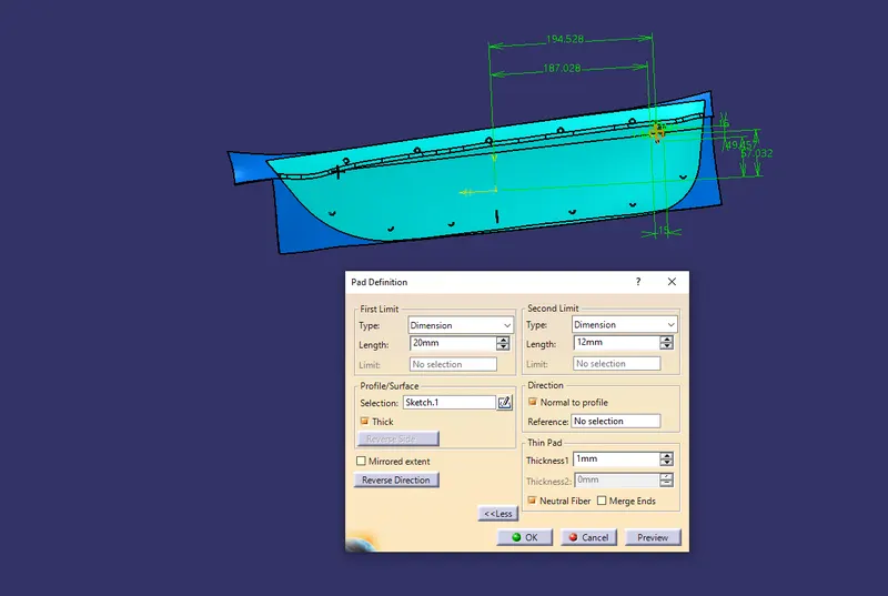
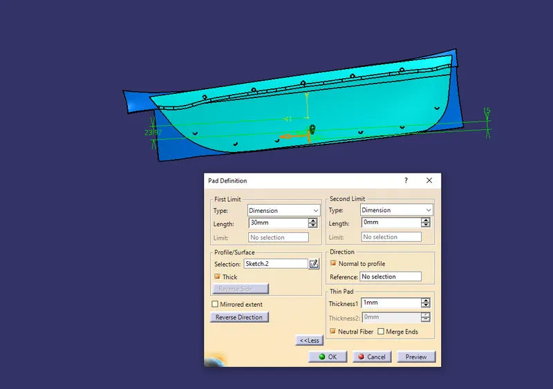
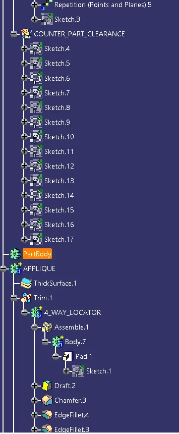
- Open the Sketcher Workbench and Draw 2 lines intersecting each other and constraint it. . Exit the Sketcher Workbench and Pad the Sketch with a thickness of 1.2 mm.
- Now, provide a draft of 0.5 degrees to the faces. Here the pulling direction is the tooling axis and the neutral face is the top face. • Provide the chamfer of 3*45 to the edges of the locators.
- For the 2-way locators, only a single line needs to created and the rest procedure is the same as 4-way locators.
HEAT STAKES:
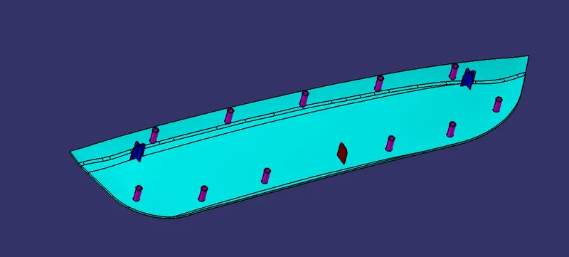
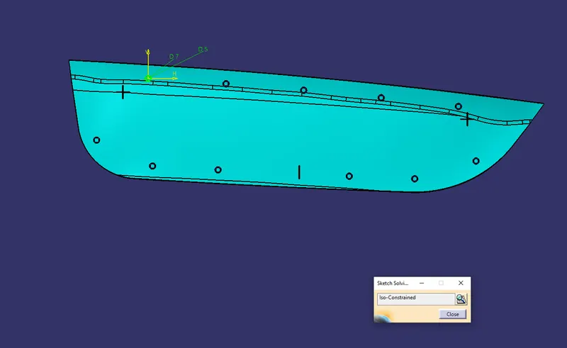
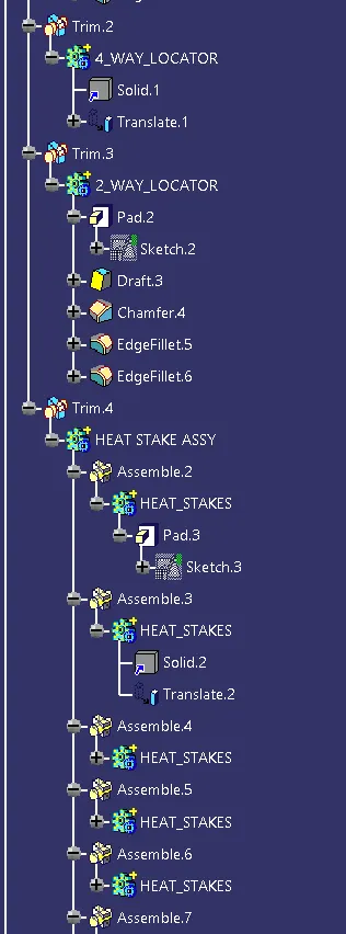
- To create the heat stakes open the Sketcher Workbench and Draw 2 circles with the Diameter of 8 and 5 mm.
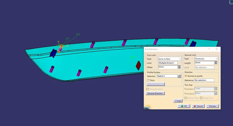
- Exit the Sketcher Workbench and Pad the Heat Stakes and draft it to 0.5 degrees.
TRANSLATION:
- Translate the 4 way locator at required position.
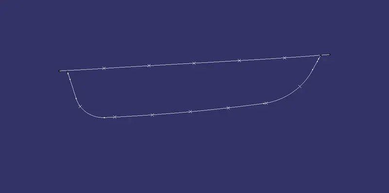
- First, the boundary curve is extracted and then this curve is parallel.
- Create the repetition of the points instances as required.
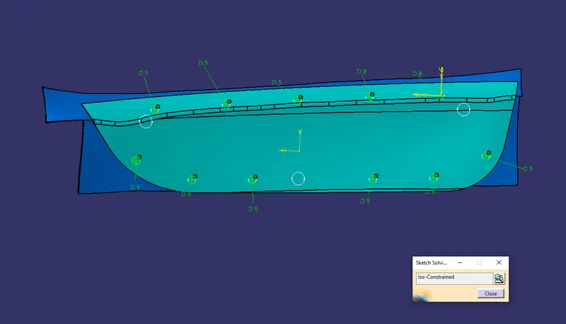
- Now, copy the heat stakes and again paste it and then use translate by a point on this copied heat stakes. Assemble all heat stakes into a body and later assemble them with the door applique.
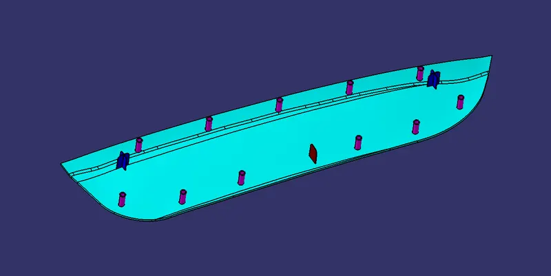
MAKING THE HOLES ON THE DOOR ATTACHMENT COMPONENT:
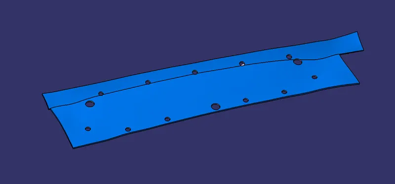
- For the created Locators and Heat skates created, there should be holes created such that the component gets fixed in the Door attachment component constraining the Degrees of freedom.
NOTE:
- Make sure the clearance with the near edges should be 0.1 for locators and 0.5 for heat stakes.
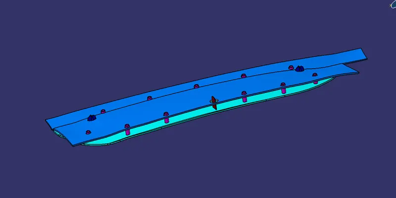
DRAFT ANALYSIS:
- To perform the draft analysis the view parameters are first set to material mode.
- Then go to Insert >>analysis>>feature draft analysis.
- First, select the axis system and drag the axis system to align and coincide with the tooling axis and lock the orientation. This axis system defines the draft direction according to the tooling axis.
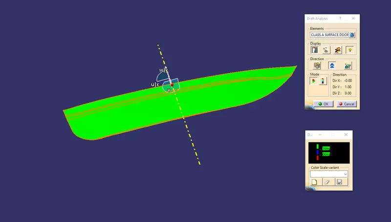
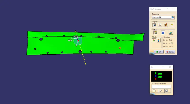
- Switch on the color scale and set the minimum draft value. Here it is set to 3 degrees and it will be displayed in green color. Any draft angle below 3 degrees will be shown in red color.
- Here, the compass direction is rotated to have the positive direction in the maximum portion of the part. Then the compass is locked in the orientation and a new tooling axis is created using the compass as the direction.
- Now select the running point tool to measure the draft angle at the various locations and then if all surfaces pass the draft analysis switch on the light effect that will show the component in green color if the component has the required draft angle.
- The bin portion of the armrest has a negative draft because the model is not accurate and has some inappropriate surface that creates the problem in the final drafting. To overcome this problem, we will need another tooling axis or sliding axis that will clear this region properly in ejection.
CLASS A:
APPLIQUE:
DOOR PANEL:
DOOR APPLIQUE MODEL:
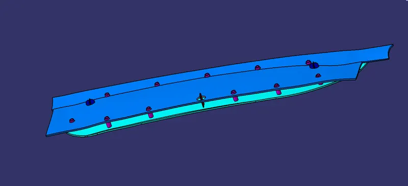
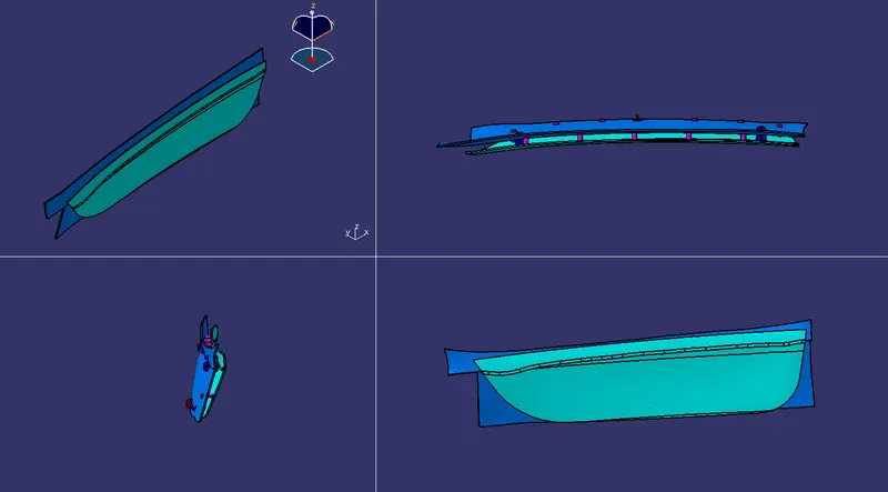
DIFFERENT VIEWS:
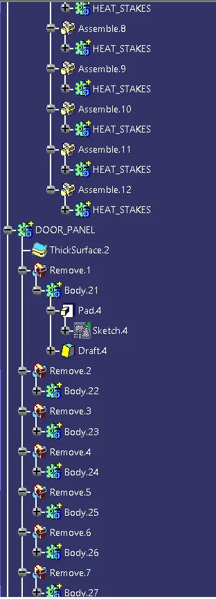
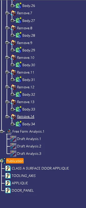
TREE STRUCTURE:
CONCLUSION:
- Thus, the Door Applique is developed by using given Class A surface.
- 2 and 4 Way locators have been designed in order to fix the position of the applique with the mating door panel and also designed the heat stakes which used to fix the component with the mating panel by melting.