Week 9 - Project 1 - Door Applique Design with Engineering Features
OBJECTIVE
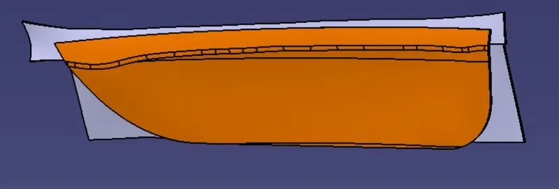
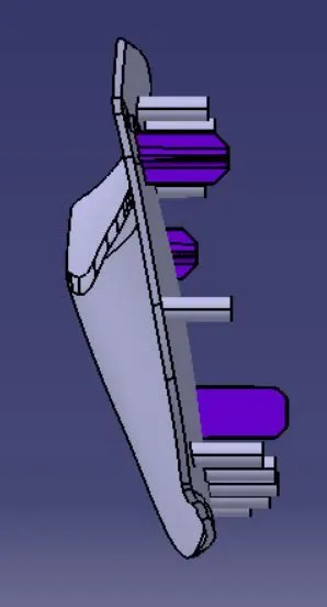
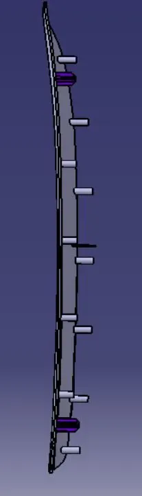
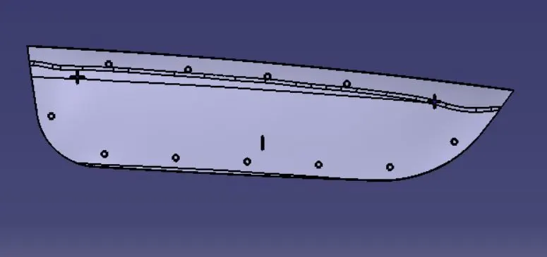
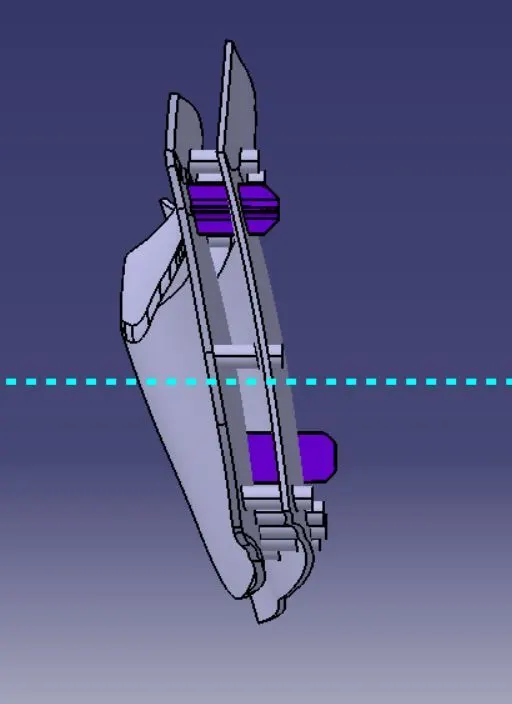
Design the Driver Door Right Hand Applique with Locators and Fixtures to assemble it onto the main inner door panel.
LOCATION PRINCIPLE
- The 3-2-1 or 6 Point Location principle is used to constrain the movement of the workpiece (to be machined/fixed) along the 3 axes XX, YY, and ZZ.
- It is achieved by providing 6 pin locations:
- 3 on Base plane.
- 2 on Vertical plane.
- 1 on the plane perpendicular to the first two planes.
- Every object has 12 DOFs and a minimum of 11 should be fixed/arrested.
HEAT STAKING
It is a plastic welding process that joins 2 dissimilar materials (Plastic-Plastic/Plastic-Metal) by controlled melting and reforming.
- The plastic stud protrudes through the hole of the parent that is to be locked with.
- The heated thermal tip contacts the top of the stud at constant pressure and melts it.
- The melted stud fills the volume of the tip cavity to produce the head for locking.
Note: The right combination of Heat and Pressure is required.
Advantages
- Simplification of Machinery.
- Reduces cost of Machinery.
- Multiple fastening points.
- Higher weld density, compared to Hot air Cold form welding or Ultrasonic welding.
TOOLING AXIS:
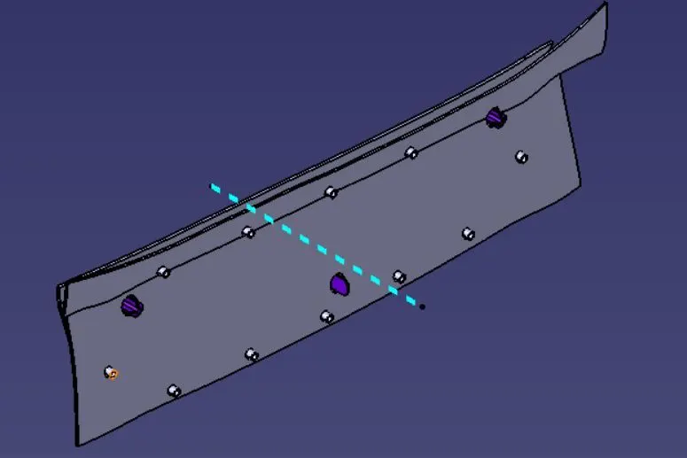
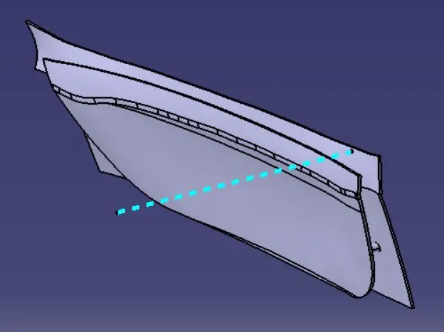
1.For tooling axis creation first extract the class A surface.
2.Then create the point on the surface of the extracted surface.
3.Draw the line perpendicular to the surface, Which is the tooling axis of the given class-A surface.
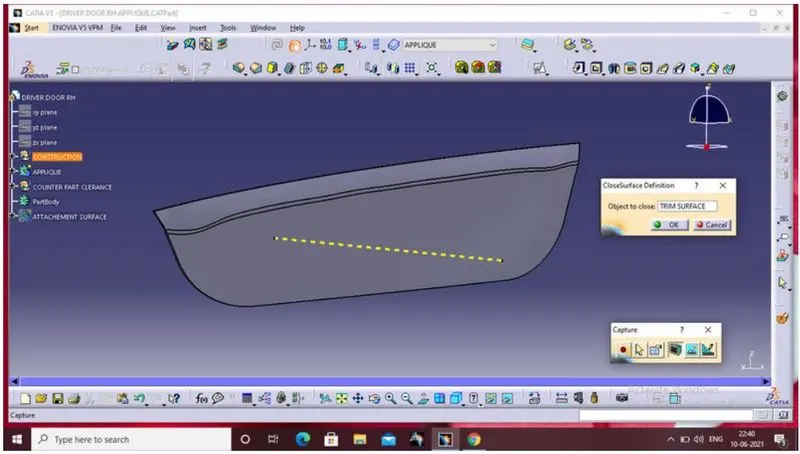
SOLID APPLIQUE BODY:
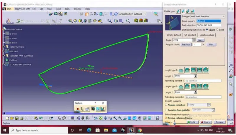
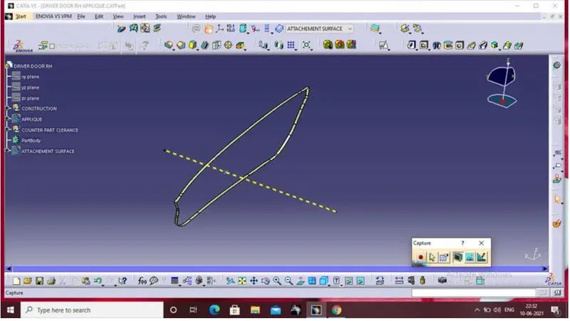
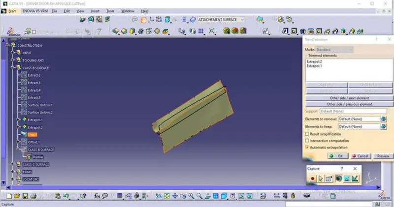
1.To make the surface body into solid body open the part workbench.
2.And open the close body command and select the surface to make it solid.
LOCATORS:
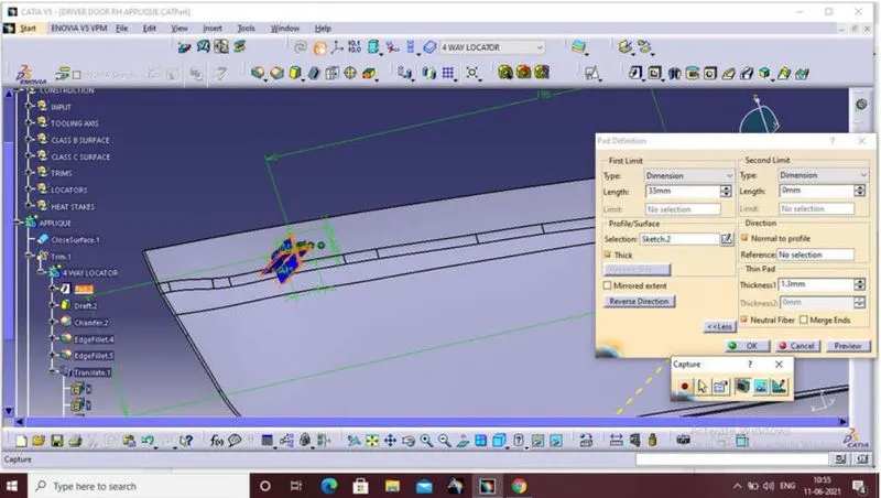
1.For the locator first extract the class A surface and create the point on the extracted surface, then insert the plane.
2.Then create the sketch on the inserted plane, Draw the locators line from the centre 15mm for both sides.
3.Next step is to pad the sketch and give locators:1. For the locator first, extract the class A surface and create the point on the extracted surface, then insert the plane.2.Then create the sketch on the inserted plane, Draw the locators line from the centre 15mm for both sides.3.The next step is to pad it the sketch and give the thickness and height value.4.Finally, add the draft and fillet values of the locator.the thickness and height value.
4.Finally add the draft and fillet values of the locator.
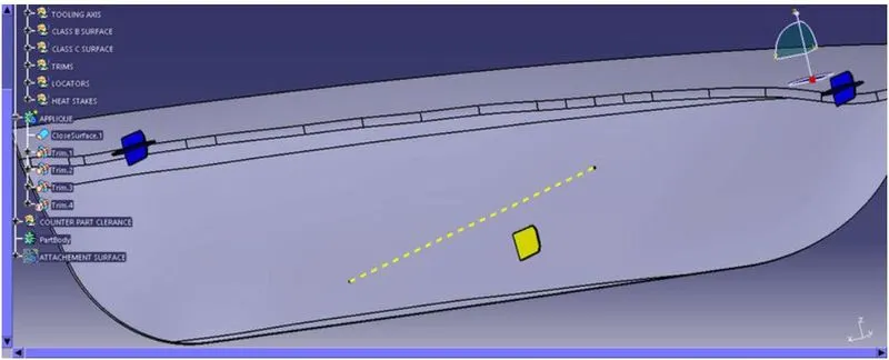
Then copy the locator and paste it again, and translate to the required destination.
Then create another sketch for a two-way locator and then pad it, and give the draft angle and radius. value. Finally, untrim with applique and locators.
To follow the design rule for rib, it is the same as the locator also.
HEAT STAKES:
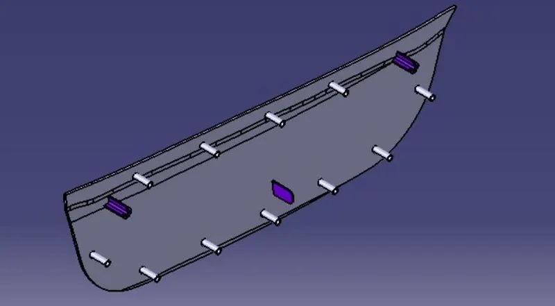
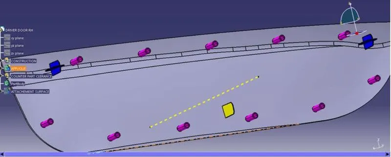
1.For heat stakes to extract the outer boundary of applique and create the required number of points on the extracted boundary.
2.Then offset the boundary of 15mm by using the parallel curve option.
3.Then draw a sketch on the plane which is used for creating locators, draw two circle dia5 @ dia7.
4.Pad the circle to the required height, then translate the heat stakes to the required number of times.
ATTACHMENT SURFACE:
1.first step is to thicken the given class A attachment surface into 2.5mm.
2.For creating the position for the locator draw the sketch and pad the sketch and give the required amount of relief and remove the pad from the attachment surface.
Position for locator
3.Follow the same way for the heat stakes position also. draw the clearance circle and pad it, then remove the pad from the attachment surface.
4.Follow the same procedure for all 12 heat stakes.
APPLIQUE DESIGN
ISOMETRIC VIEW
FRONT VIEW
TOP VIEW
SIDE VIEW
DOOR APPLIQUE DESIGN
ISOMETRIC VIEW
FRONT VIEW
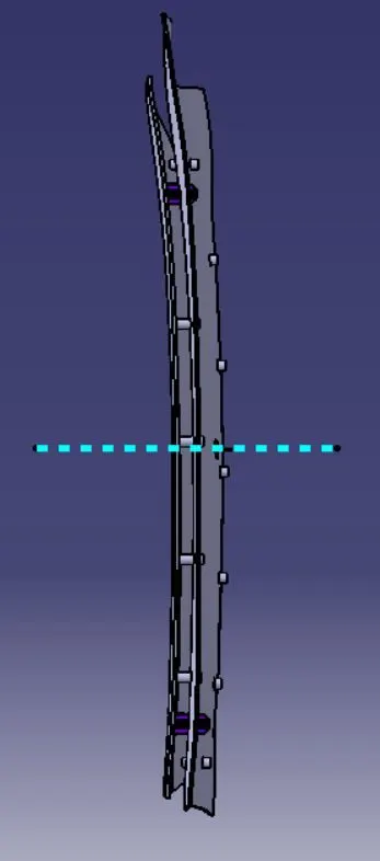
SIDE VIEW
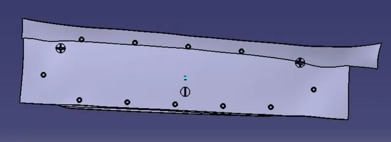
TOP VIEW
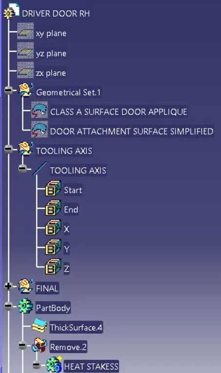
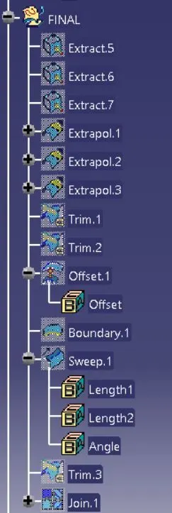
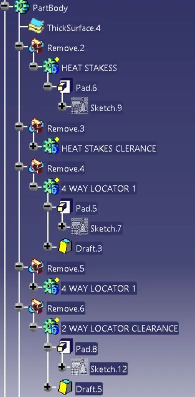
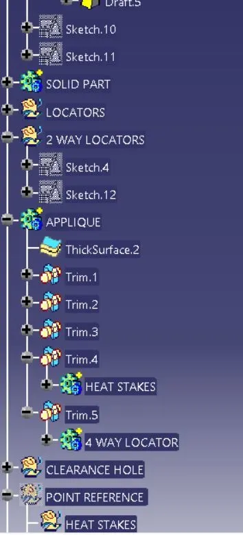
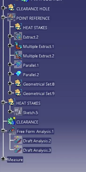
TREE STRUCTURE