Attachment Feature Creation
DESIGN OF ATTACHMENT FEATURE FOR APPLIQUE MODEL IN DRIVER DOOR PANEL
AIM
1. Create a solid body from the class A surface of the Door Applique
2. Follow industrial design rules to create tooling axis and perform draft analysis on the Door Applique
3. Design attachment features like Locators and Heat Stakes for fixing the Door Applique with the Door panel.
INTRODUCTION
This project will be designed based on the standards followed by the industry for making attachments on the body of a component to fix with the main body. The Door Applique will be fixed to the Door panel with the help attachment features created based on the 3-2-1 Taylors principle.
Applique
Applique is the aesthetic part which is present on the door panel for giving better look to the door. The thickness of this component given is 2.5 mm which is an ideal thickness for injection moulding process.
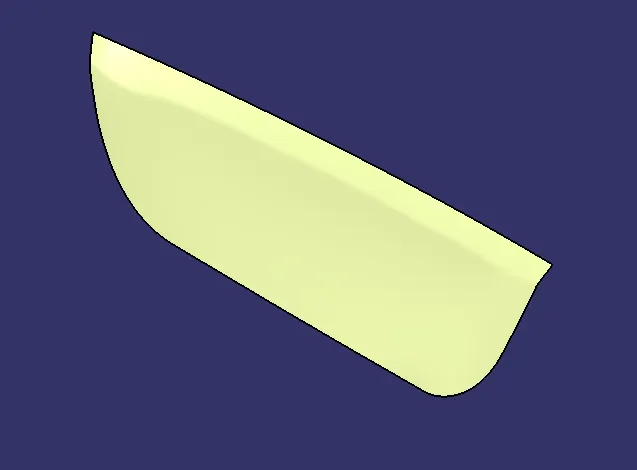
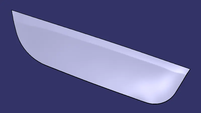
The design of class A surface of Applique is shown below
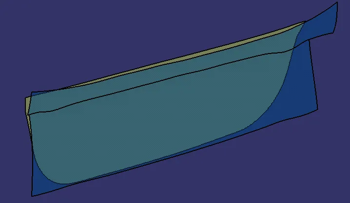
The attachment of the applique which will be fixed to the door panel is shown below:
Design of Class B surface
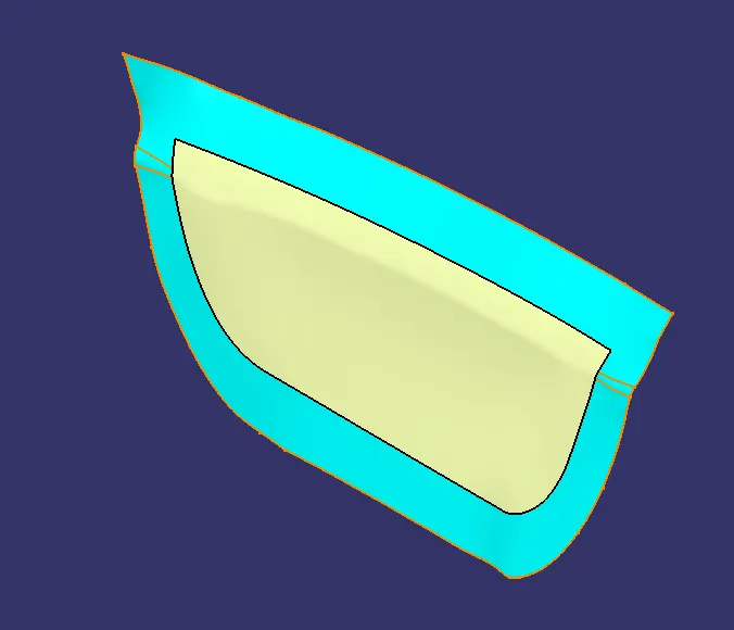
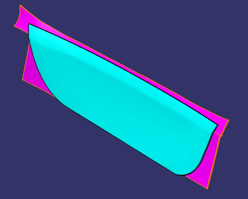
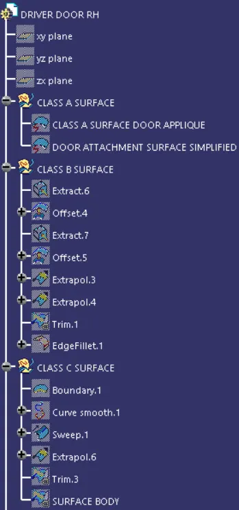
1. The first step in making the class B for the component is to extract the surfaces of the class A surface and then offset it at a distance of 2.5 mm.
2. Then the boundaries of the offseted surface are extrapolated and then trimmed with each other to give the desired shape.
The below figure shows the class B surface in cyan colour.
Design of Class C surface
1. The class C surface is made by extracting the boundary of the class A surface and then smoothening the boundary for the smooth curvature of the boundary surface.
2. Sweep feature is used to create the C surface by giving direction of sweep to be in tooling direction with a 3 degree draft. This operation is shown below
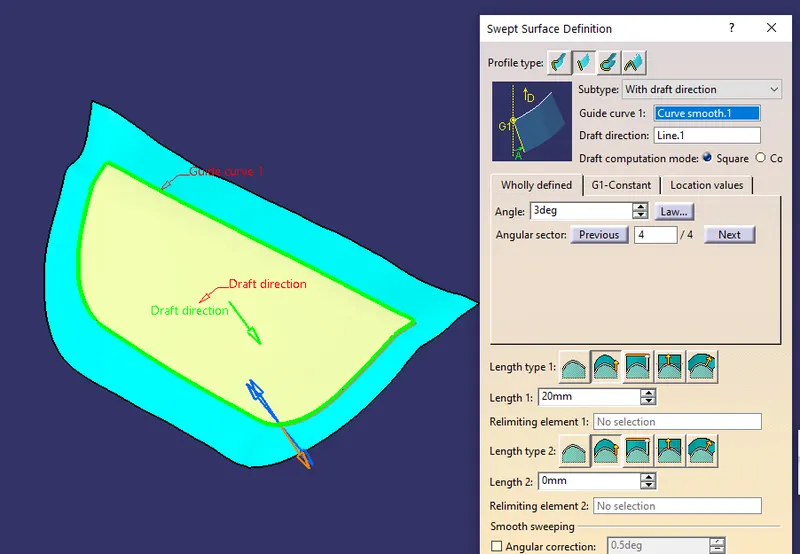
3. After this operation the surface of sweep is trimmed with both the class A and class B surfaces to create the complete surface body.
When Class A, Class B and Class C surfaces are designed and combined together it is doubled checked whether the surfaces are not open from any side with the help of boundary feature.
After ensuring this, surface body is converted in solid body with the help of closed body feature in part design work bench in Catia.
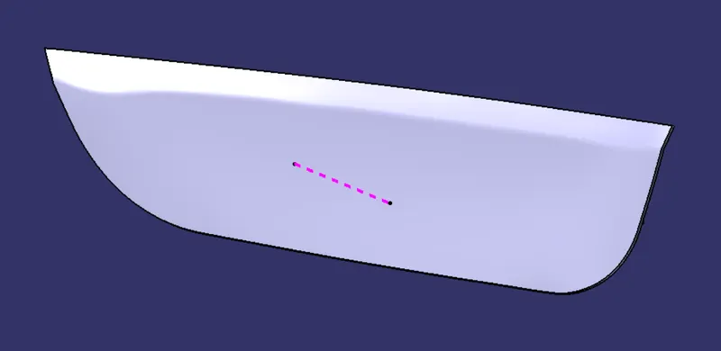
Determination of tooling axis for the Applique
The tooling axis of the component is determined by first generating the point on the centre of the surface and then creating a line in perpendicular direction to check the draft analysis for the component.
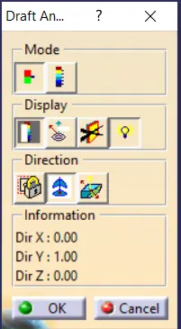
Draft Analysis
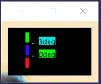
The draft analysis on the component is done by giving an input of 3 degrees as the limit for safe removal of the component from the mould.
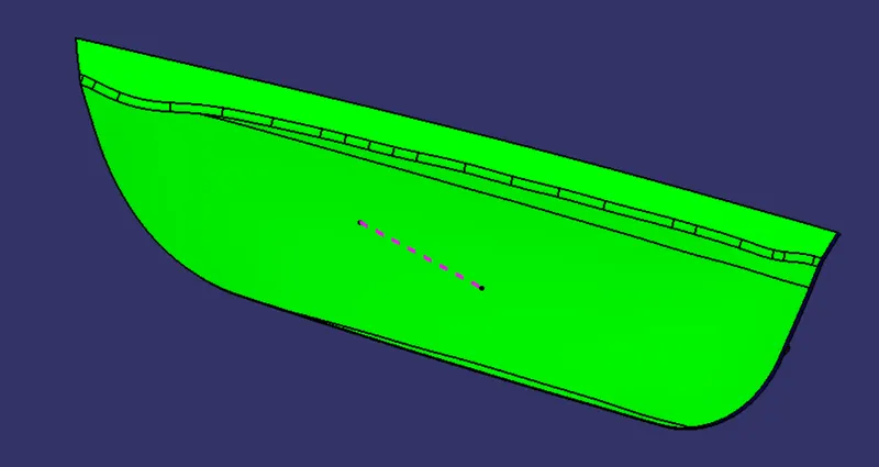
Colour Indications
Green: This indicates that angle above 3 degree is safe and can be easily removed from the mould.
Blue: Angle between 0 to 3 degrees.
Red: Angle below 0 degrees and unsafe.
Hence from the above analysis we can observe that the component tooling axis is positioned in the correct direction and the injection moulding operation can be performed for the Applique safely.
Attachment features for the Applique
The attachment features that are used for this component are
1. Heat Stakes
2. 4 way locators
3. 2 way locator
1. Heat Stakes
Heat stakes is the attachment feature which is used in automobile industry for joining two dissimilar materials together.
In this process heating and cooling of the plastic component is done to raise the temperature of the plastic components and allow plastic reforming to be carried out.
The benefits of this techniques are:
1. No vibrational damage
2. No particulates
3. Reduced cost
2. 4 way and 2 way locators
The locators are used to restrict the motion of the component. Generally, every component has 12 degrees of freedom which allows various motions for the component in different directions.
In order to locate the fixation of parts and arrest the degree of freedom for the component 3-2-1 Taylors principle is used:
The 12 different degrees of freedom are:
1. Translation movement along X - axis. (Positive and Negative)
2. Translation movement along Y - axis. (Positive and Negative)
3. Translation movement along Z - axis. (Positive and Negative)
4. Rotational movement along X - axis. (Clockwise and anti- clockwise)
Rotational movement along X - axis. (Clockwise and anti- clockwise)
Rotational movement along X - axis. (Clockwise and anti- clockwise)
In order to fix a component to a body, we must arrest at least 11 degrees of freedom.
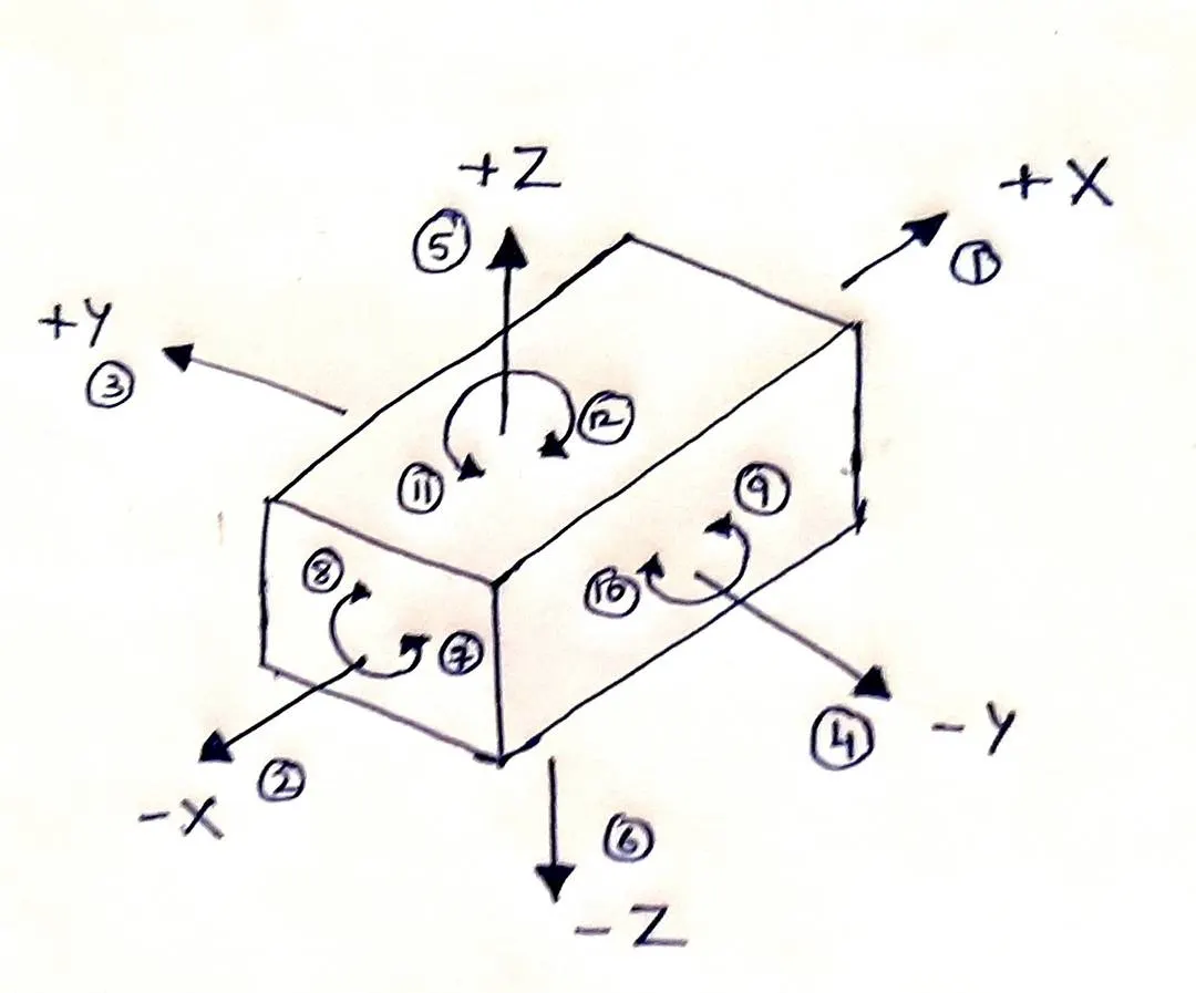
4 Way and 2 Way locators are used to perform this task.
The industrial design standards were used to make the locators and the heat stokes for the component.
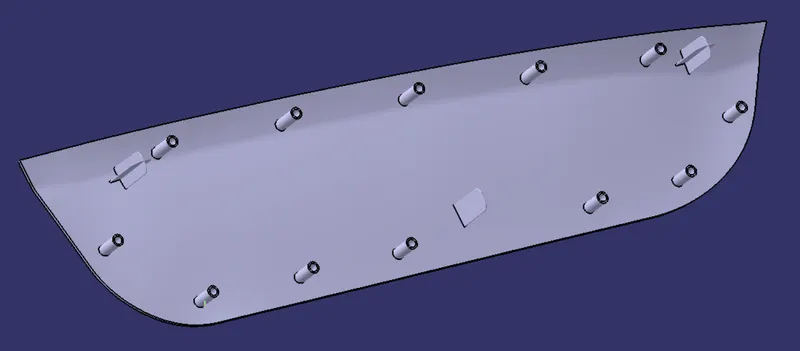
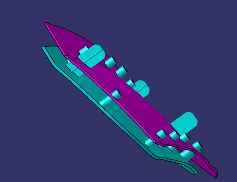
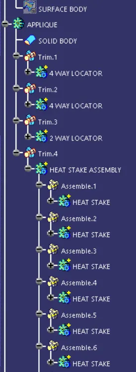
The locators were attached to the Applique with the help of add feature using Boolean operations. Chamfer was given at the top of the locator for feasible fixation mechanism.
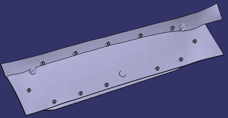
A counterpart clearance of 0.1 mm for the locators and 0.5 mm for the heat stakes was given from the Door attachment body to the surfaces of locators and heat stakes.
The heat stakes were made inside the boundary of the applique at equal distances.
The attachment features attached to the applique is shown below:
Attachment features along with the Door attachment body is shown below:
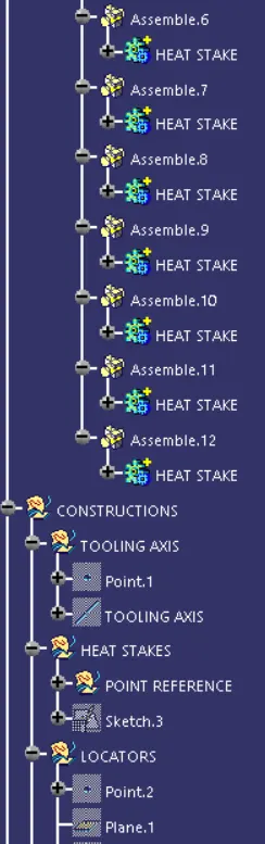
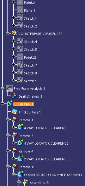
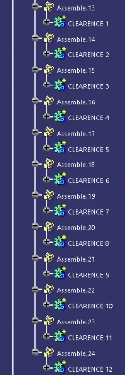
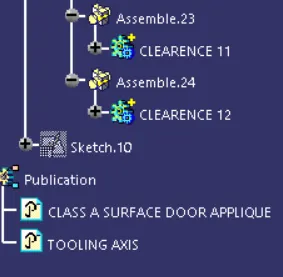
The detailed tree structure for creation of this project is shown below:
CONCLUSION
1. The class A surface was converted into a surface body and then solid body was formed for the injection moulding process.
2. Draft Analysis was carried out on the component to determine the correct direction of the tooling axis for safety of the component.
3. Attachment features were attached to the Applique following the industry standards for fixing the component to the main door panel.