Week 9 - Parametric study on Gate valve.
AIM
To perform gate valve simulation .
OBJECTIVE
- Obtain the mass flow rates at the outlet for each design point.
- Calculate the flow coefficient and flow factor for each opening and plot the graph.
- Discuss the results of the mass flow rate and flow coefficient.
GATE VALVE
The working principle of a gate valve is based on the movement of a gate or disc to control the flow of fluid. The gate is positioned inside the valve body and moves either vertically (rising stem gate valve) or horizontally (non-rising stem gate valve) to open or close the valve.
Here is a step-by-step explanation of the working principle of a gate valve:
-
Open position: When the gate valve is fully open, the gate or disc is raised completely, allowing unobstructed flow through the valve. The fluid enters the valve through the inlet port and exits through the outlet port.
-
Closing the valve: To close the valve, the operator rotates the handwheel or actuator in the clockwise direction (for rising stem valve) or rotates the stem in the anti-clockwise direction (for non-rising stem valve). This causes the gate to lower gradually, obstructing the flow path.
-
Throttling: As the gate starts to lower, it initially restricts the flow, gradually reducing the opening until the gate is fully closed. Gate valves are primarily designed for on/off service, so throttling or controlling the flow rate at intermediate positions is not recommended.
-
Closed position: When the gate valve is fully closed, the gate or disc is positioned tightly against the valve seat, providing a tight shut-off and preventing any flow through the valve.
-
Opening the valve: To open the valve, the operator rotates the handwheel or actuator in the counter-clockwise direction (for rising stem valve) or rotates the stem in the clockwise direction (for non-rising stem valve). This raises the gate, gradually opening the flow path.
It's important to note that gate valves are often operated slowly due to the rising or rotating motion required to open or close the valve. This slow operation is necessary to prevent damage to the valve and to minimize the risk of water hammer or pressure surges in the pipeline.
Gate valves are commonly used in applications where a full flow path is desired and quick shut-off is required. They are often used in systems with high-pressure or high-temperature fluids, such as in oil and gas pipelines, water treatment plants, power generation plants, and industrial processes.
Flow coefficient
The flow coefficient of a device is a relative measure of its efficiency at allowing flui flow. It describes the relationship between the pressure drop across an orificevalve or other assembly and the corresponding flow rate.
Mathematically the flow coefficient Cv (or flow-capacity rating of valve) can be expressed as :

where:
- Q is the rate of flow (expressed in US gallons per minute),
- SG is the specific gravityof the fluid (for water = 1),
- ΔP is the pressure drop across the valve (expressed in psi).
In more practical terms, the flow coefficient Cv is the volume (in US gallons) of water at 60 °F that will flow per minute through a valve with a pressure drop of 1 psi across the valve.
The use of the flow coefficient offers a standard method of comparing valve capacities and sizing valves for specific applications that is widely accepted by industry. The general definition of the flow coefficient can be expanded into equations modeling the flow of liquids, gases and steam using the discharge coefficient.
Flow factor
The metric equivalent flow factor (Kv; commonly used everywhere else in the world with the exception of the United States) is calculated using metric units :

where
Kv is the flow factor (expressed in ).
).
Q is the flowrate (expressed in cubic metres per hour ]),
]),
SG is the specific gravityof the fluid (for water = 1),
ΔP is the pressure drop across the valve (expressed in psi).
Kv can be calculated from Cv using the equation:

PROCEDURE
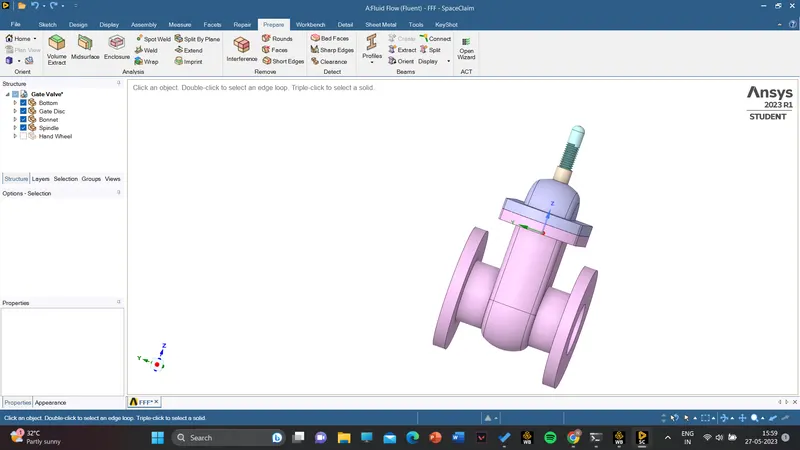
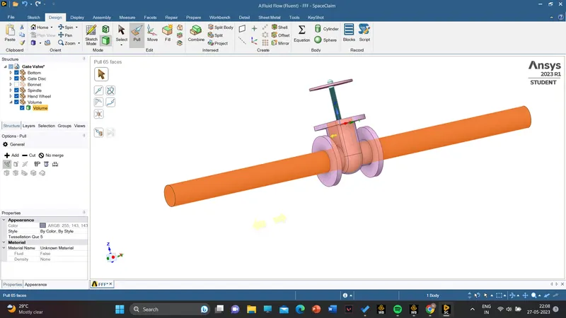
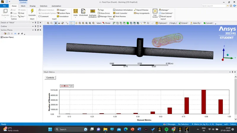
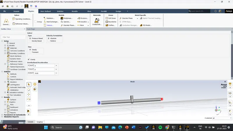
Import the geometry

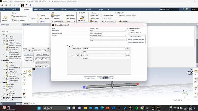
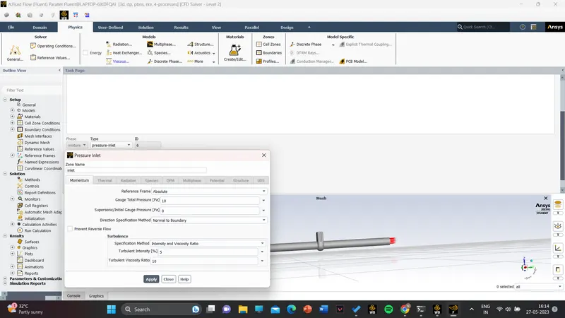
results
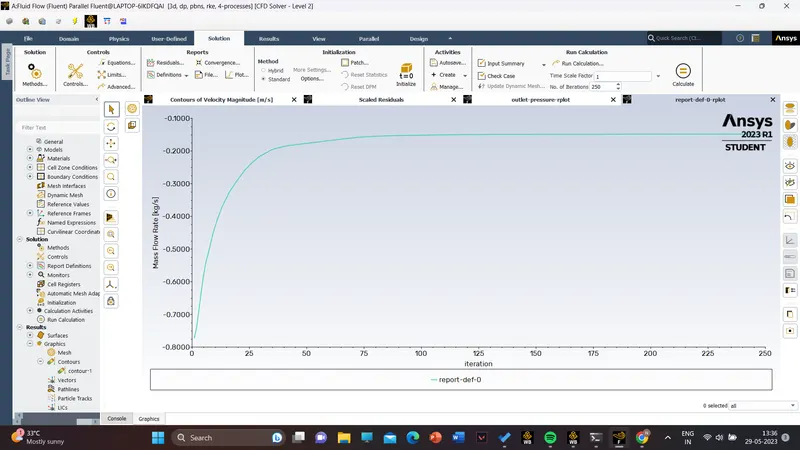
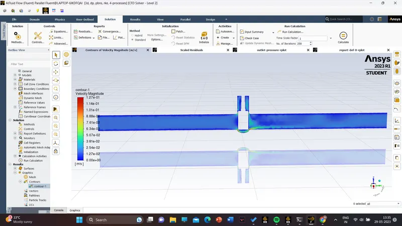
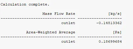
lift 10 mm
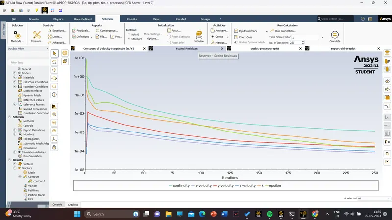
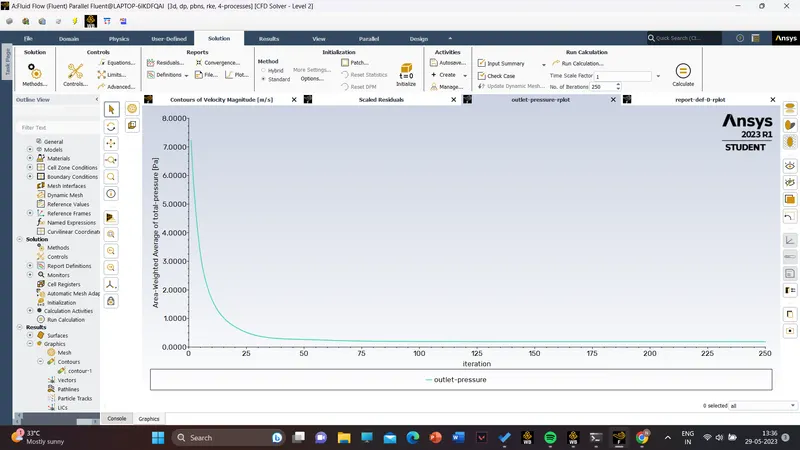
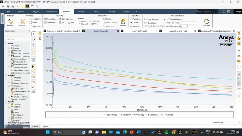
lift 20 mm
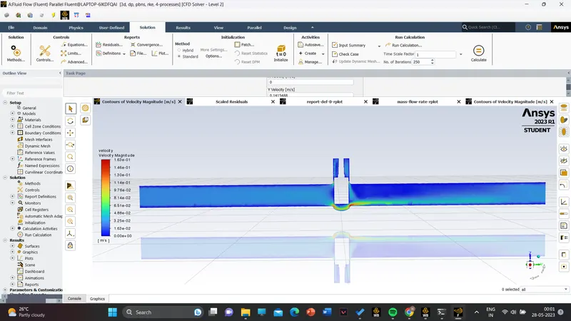
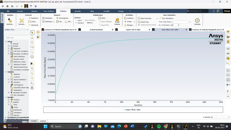
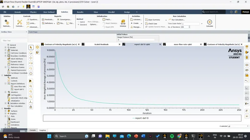
lift 30 mm
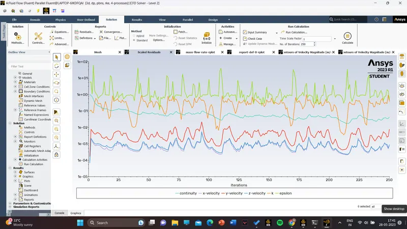
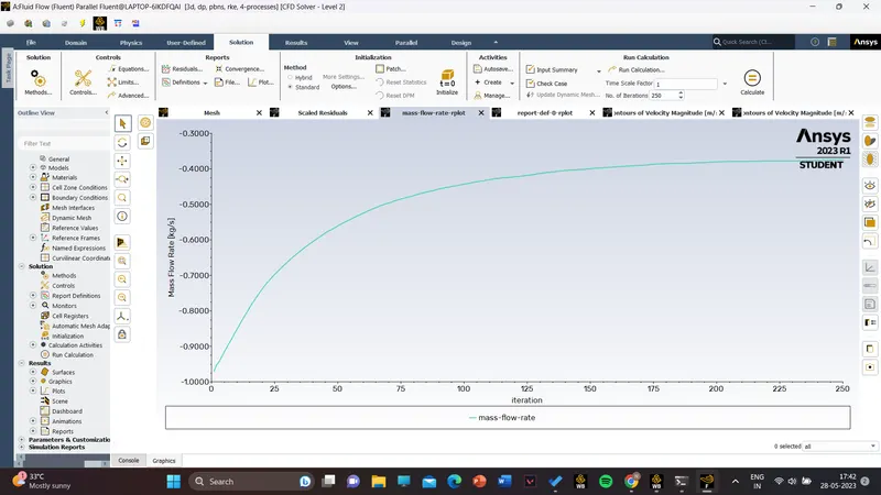
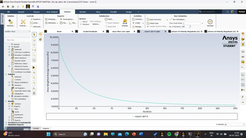
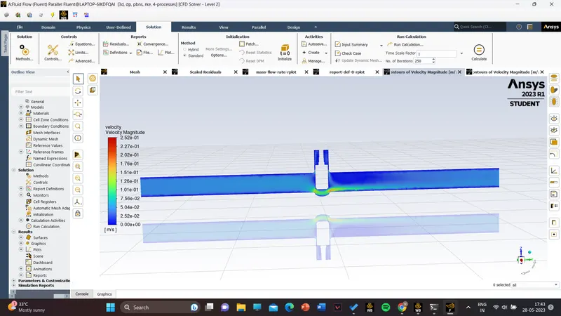
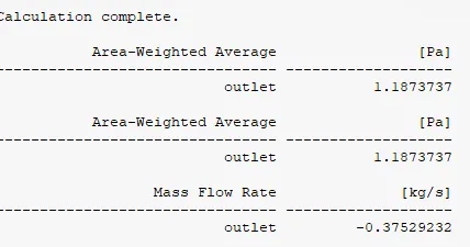
lift 40 mm
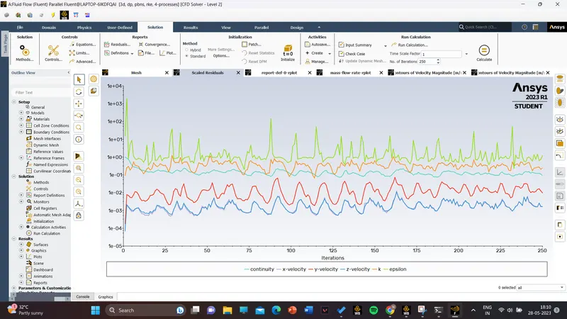
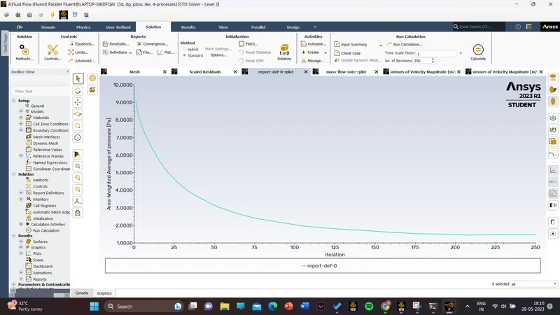
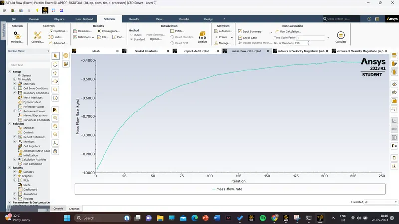
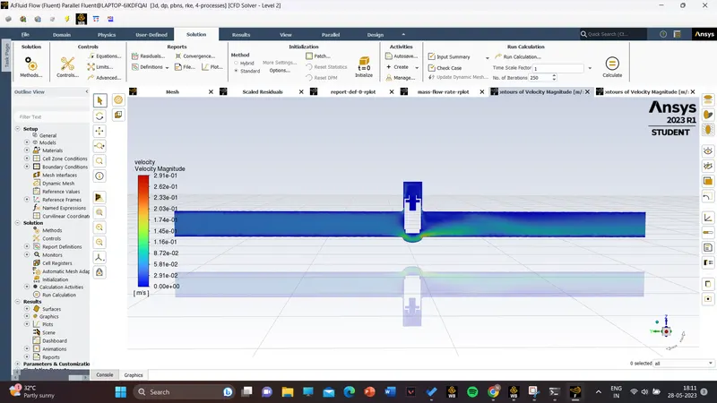
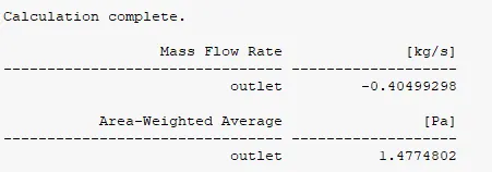
similarly ,simulations are done for 50,60,70,80 and results are given below ,
| design points | mass flowrate(kg/s) | outlet pressure (pa) | pressure difference (pa) | flow coefficient(Cv) | flow factor(Kv) |
| 10 | -0.148 | 0.186 | 9.814 | 62.2 | 53.74 |
| 20 | -0.239 | 0.485 | 9.515 | 102.12 | 88.33 |
| 30 | -0.375 | 1.187 | 8.813 | 166.8 | 144.29 |
| 40 | -0.404 | 1.477 | 8.523 | 182.57 | 157.92 |
| 50 | -0.564 | 2.939 | 7.061 | 273.67 | 236.7 |
| 60 | - 0.696 | 3.485 | 6.514 | 331.2 | 338.63 |
| 70 | -0.729 | 4.248 | 5.751 | 391.4 | 338.63 |
| 80 | -0.783 | 5.135 | 4.864 | 457.168 | 395.47 |
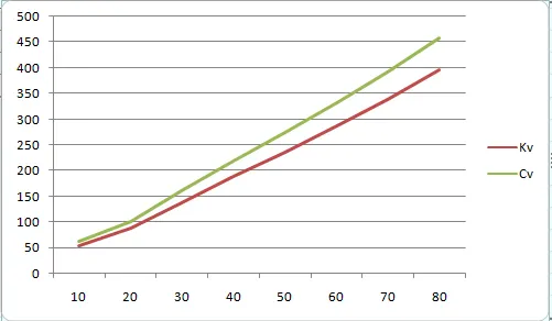
Here x axis represents the opening of the gate valve and the y axis represents the value of Kv and Cv.
Here it can be noticed that as the lift heifght increses the pressure drop also decreases and the flow coefficient also increases. Further high flow coefficient offers less frictionoll losses and the high pressure flow through the valve with very low pressure drop.
Conclusions:
- The low lift height refers to the higher pressure drop and thus low flow rate through the valve.
- The negative mass flow is due to the mass exiting the outlet.
- With the help of the parameters the solving time and effort can be reduced drastically.
- Flow factor and coefficient increases as the mass flow rate through the valve increases.