Week 9 - Parametric study on Gate valve.
sir,there is some problem in my laptop ,my laptop is not take snap shot i use mbile snap shot .plz sir understand my problem so Sir plz dont reduce mark
AIM
For this challenge, you will have to perform a parametric study on the gate valve simulation by setting the opening from 10 % to 80%.
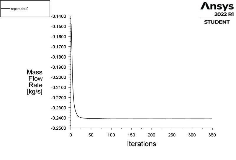
- Obtain the mass flow rates at the outlet for each design point.
- Calculate the flow coefficient and flow factor for each opening and plot the graph.
- Discuss the results of the mass flow rate and flow coefficient
INTRODUCTON THEORY:
A gate valve also known as a sluice valve is a valve which opens by lifting a round or rectangular gate/wedge out of the path of the fluid. The distinct feature of a gate valve is the sealing surfaces between the gate and seats are planar, so gate valves are often used when a straight-line flow of fluid and minimum restriction is desired. The gate faces can be parallel, but are most commonly wedge-shaped. Gate valves are primarily used to permit or prevent the flow of liquids, but typical gate valves shouldn't be used for regulating flow, unless they are specifically designed for that purpose. Because of their ability to cut through liquids, gate valves are often used in the petroleum industry. For extremely thick fluids, a specialty valve often known as a knife gate valve is used to cut through the liquid. On opening the gate valve, the flow path is enlarged in a highly nonlinear manner with respect to percent of opening. This means that flow rate does not change evenly with stem travel. Also a partially open gate tends to vibrate from the fluid flow. Most of the flow change occurs near shutoff with a relatively high fluid velocity causing gate and seat wear and eventual leakage if used to regulate flow. Typical gate valves are designed to be fully opened or closed. When fully open, the typical gate valve has no obstruction in the flow path, resulting in very low friction loss.
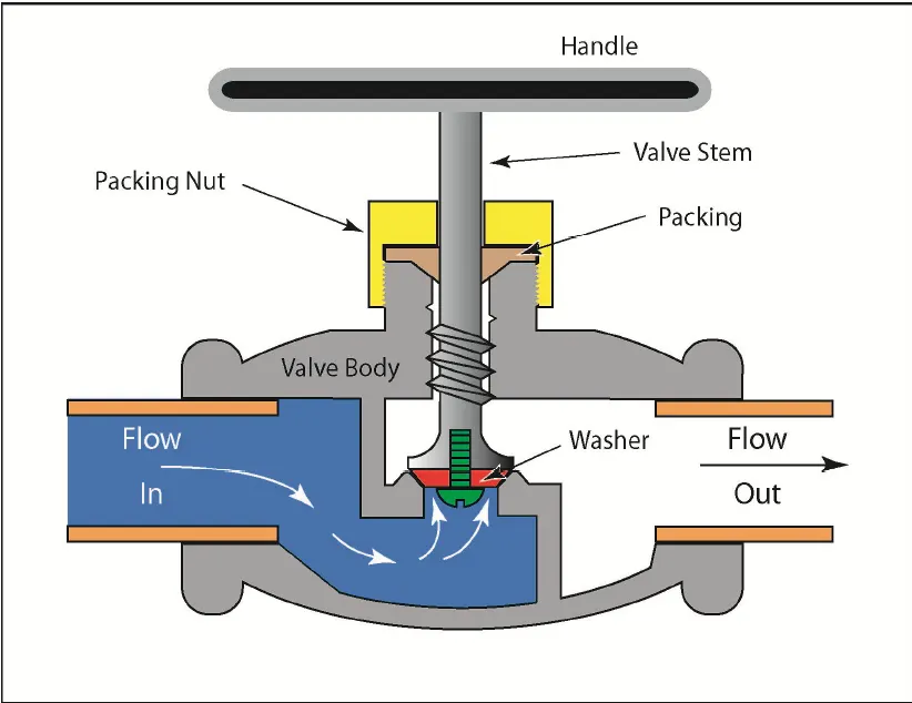
Gate valves are actuated by a threaded stem which connects the actuator (e.g. hand wheel or motor) to the gate. They are characterized as having either a rising or a non rising stem, depending on which end of the stem is threaded. Rising stems are fixed to the gate and rise and lower together as the valve is operated, providing a visual indication of valve position.
The actuator takes the form of a nut which is rotated around the threaded stem to move it. Non rising stem valves are fixed to, and rotate with, the actuator, and are threaded into the gate. They may have a pointer threaded onto the upper end of the stem to indicate valve position, since the gate's motion is concealed inside the valve. Non rising stems are used underground
or where vertical space is limited. Gate valves are primarily designed to serve as isolation valves. In service, these valves generally are either fully open or fully closed. When fully open, the fluid or gas flows through the valve in a straight line with very little resistance. It should not be used in the regulation or throttling of flow because accurate control is notpossible. Furthermore, high-flow velocity in partially opened valves may cause erosion of the discs and seating surfaces. Vibration may also result in chattering of the partially opened valve disc. An exception to the above are specially designed gate valves that are used for lowvelocity
throttling; for example, guillotine gate valves for pulp stock.
Flow coefficient
The flow coefficient of a device is a relative measure of its efficiency at allowing flui flow. It describes the relationship between the pressure drop across an orificevalve or other assembly and the corresponding flow rate.
Mathematically the flow coefficient Cv (or flow-capacity rating of valve) can be expressed as :

where:
- Q is the rate of flow (expressed in US gallons per minute),
- SG is the specific gravityof the fluid (for water = 1),
- ΔP is the pressure drop across the valve (expressed in psi).
In more practical terms, the flow coefficient Cv is the volume (in US gallons) of water at 60 °F that will flow per minute through a valve with a pressure drop of 1 psi across the valve.
The use of the flow coefficient offers a standard method of comparing valve capacities and sizing valves for specific applications that is widely accepted by industry. The general definition of the flow coefficient can be expanded into equations modeling the flow of liquids, gases and steam using the discharge coefficient.
Flow factor
The metric equivalent flow factor (Kv; commonly used everywhere else in the world with the exception of the United States) is calculated using metric units :

where
Kv is the flow factor (expressed in ).
).
Q is the flowrate (expressed in cubic metres per hour  ]),
]),
SG is the specific gravityof the fluid (for water = 1),
ΔP is the pressure drop across the valve (expressed in psi).
Kv can be calculated from Cv using the equation:

PROCEDURE:
> Import the geometry in the spaceclaim.
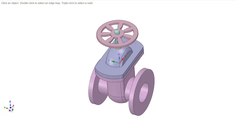
> perform the parameterization.
> Disable all the solid components except the gate dic and spindle.
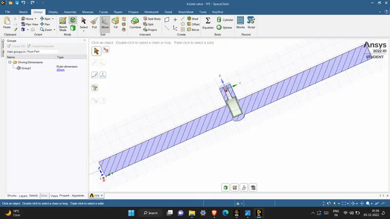
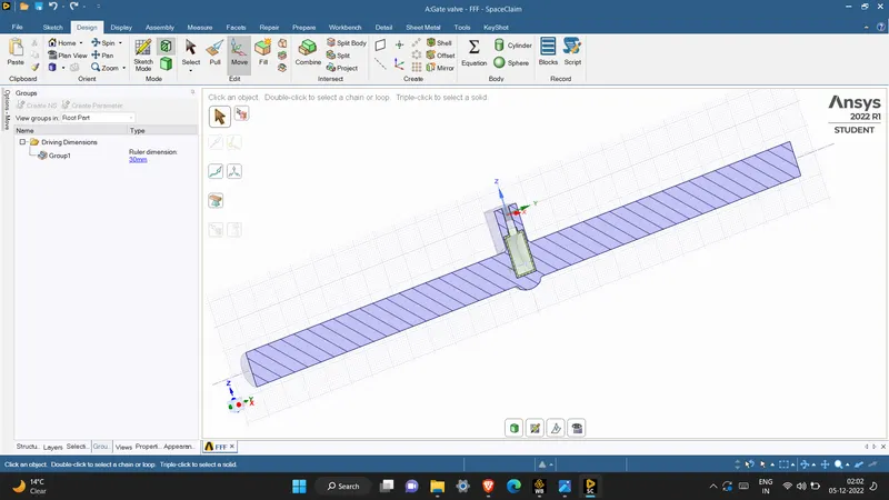
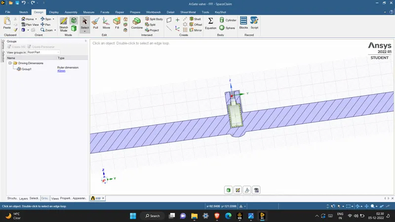
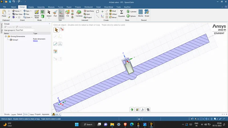
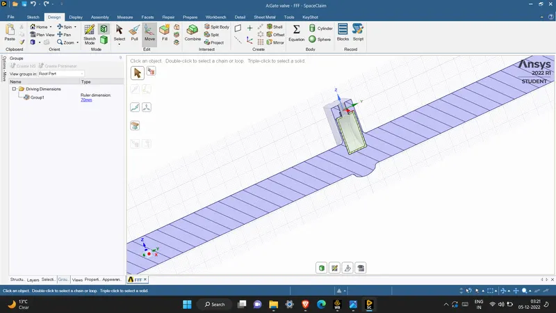
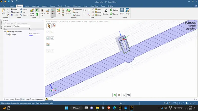
> Go to the design tab and choose the move option and further select move body option and further select the gate disc.Following you will be able to see the coordinate system appear the gate disc,you can then proceed to move the gate disc towards the top of the spindle.
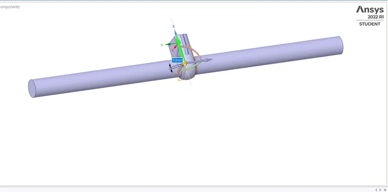
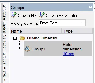
> As shown in the image the create parameter option doesnot appear along the dimension of the lift the alternate way to parametrize the same is to go to the groups menu which is adjacent to the structured menu, in the group menu you will able to see the create parameter button,which will be enabled only after you have move the gate disc,click on create parameter following which you will you see a group 1 appear in which you can edit the dimensions of the lift.This will parameterise your gate disc lift,you can confirm the same by checking your workbench.
> Extract the fluid volume.
Prepare > volume extract > select edges > press green tick symbol.
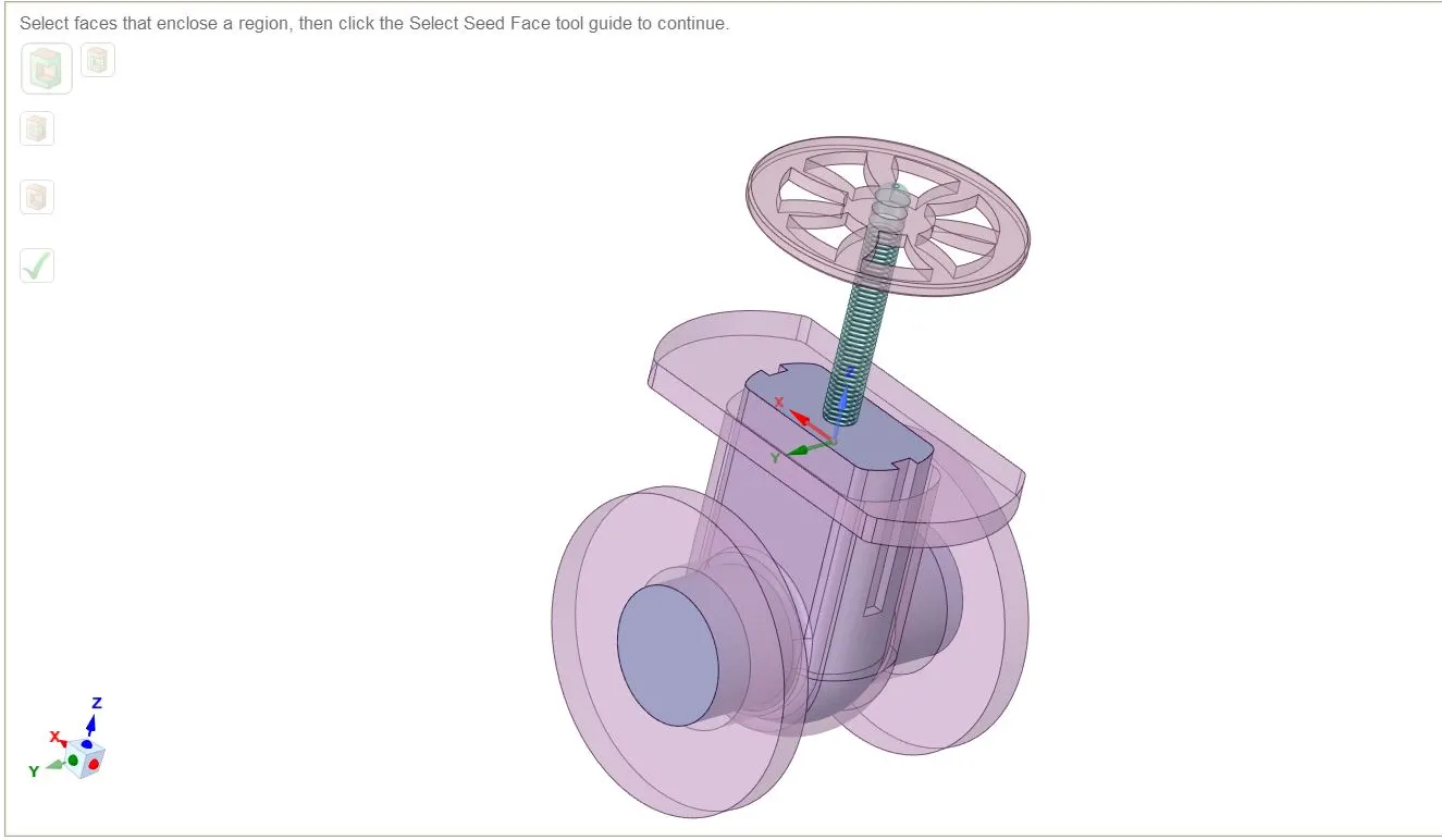
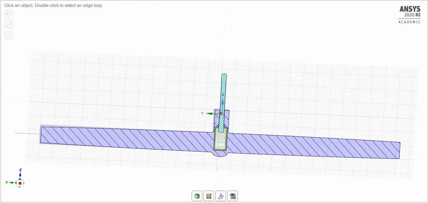
> Volume is extracted and it is confirm by the orange colur volume showing in the image.
Check the fluid volume Whether it is properly aligned with the disc.
Meshing:
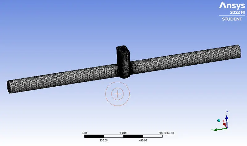
- Open the mesh console.
- For the mesh size choose default mesh element size >> click on generate mesh.
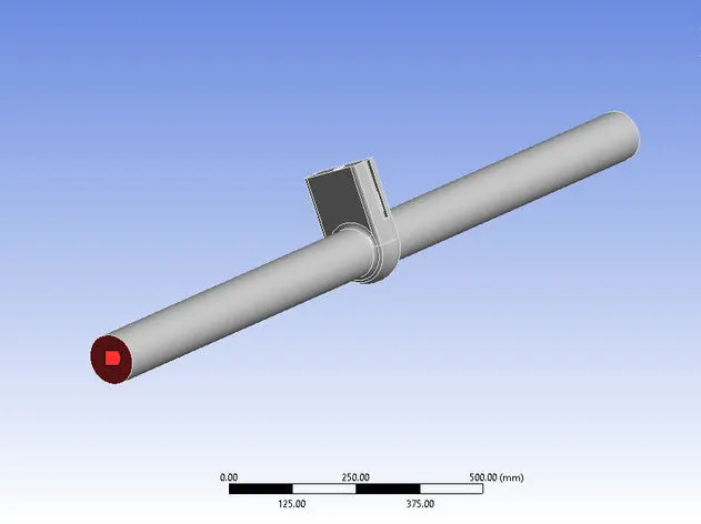
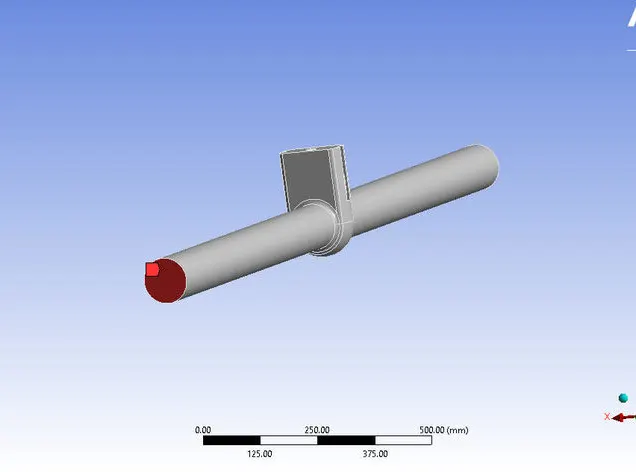
- Create named selection for the inlet and outlet section.
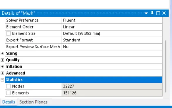
TOTAL NUMBER OF ELEMENTS ARE:
PRE PROCESSING:
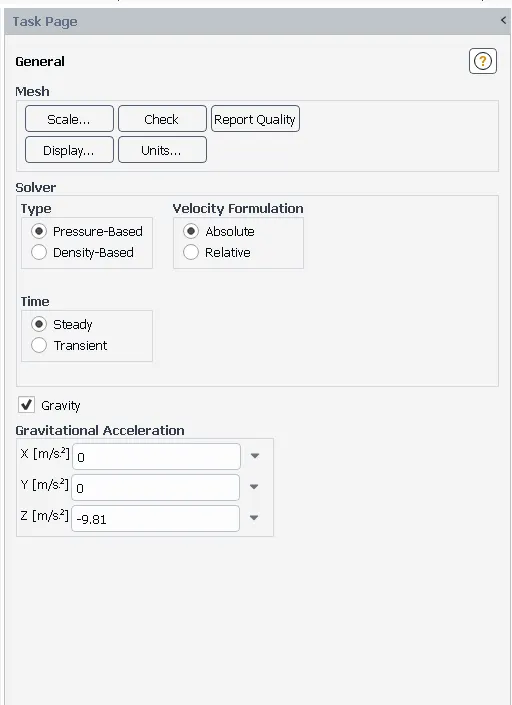
SOLVER TYPE PRESSURE BASED
SOLVER TIME STEADY STATE
GRAVITY ON (Z AXIS -9.8M/S)
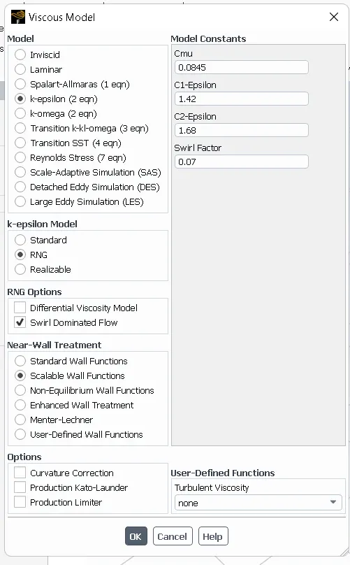
VISCOUS MODEL K-EPSILON ,REALIZABLEW,SWIRL FLOW,SCALABLE
WALL FUNCTION
MATERIAL WATER
METHOD COUPLED
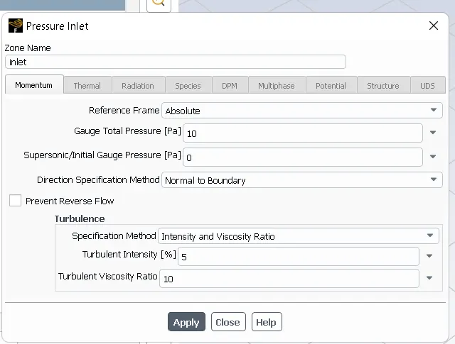
INLET(PRESSURE INLET) 10Pa
OUTLT PRESSURE OUTLET(0Pa)
> Perform general setup such as solver time as steady state, solver time as pressure based and enable gravity.
> use viscous model as k-epsilon realizable swirl scalable.
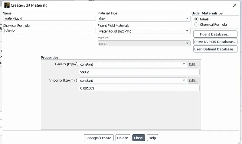
> use material as water
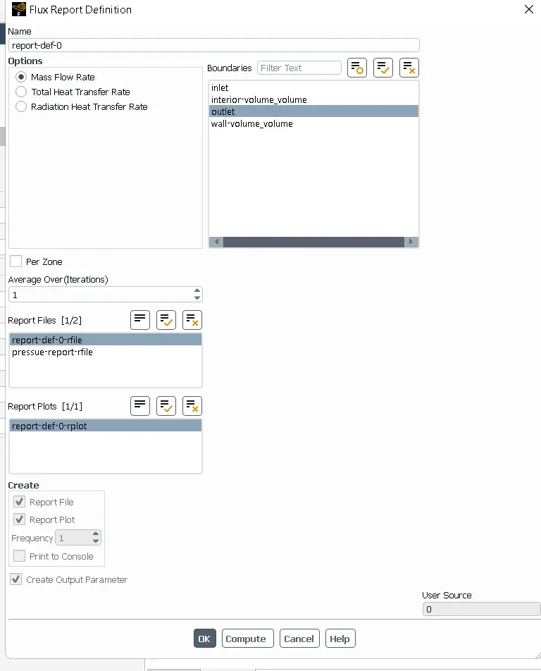
> Create the plot for the mass flow rate at outlet and parametrise it to view the results in the project schematic window.
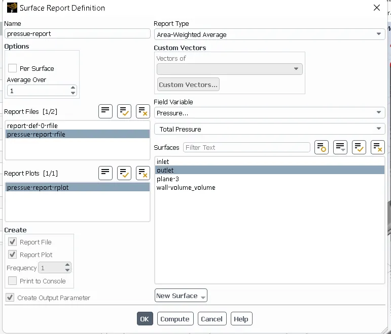
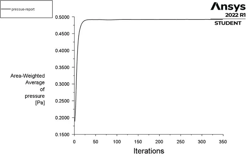
> Create the plot for the pressure at outlet and do parametrise it.
> set the boundary conditions. select inlet boundary selection as pressure inlet.
> select outlet boundary type as pressure outlet.
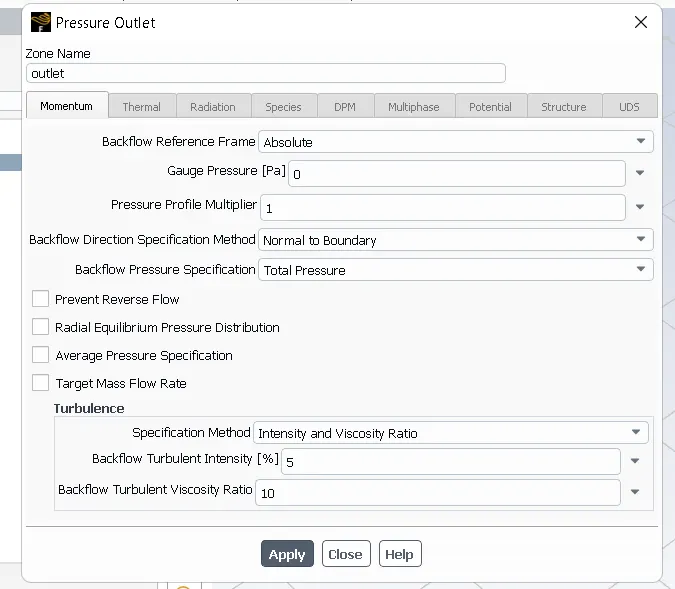
> initialize the problem using standard initialization.
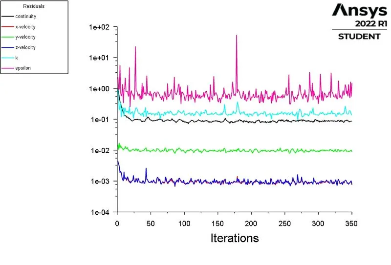
> Run the simulation for 350 iterations.

> RESULTS:
CASE 1:
DESIGN POINT 1: GATE DISC OPENING IS 10mm.
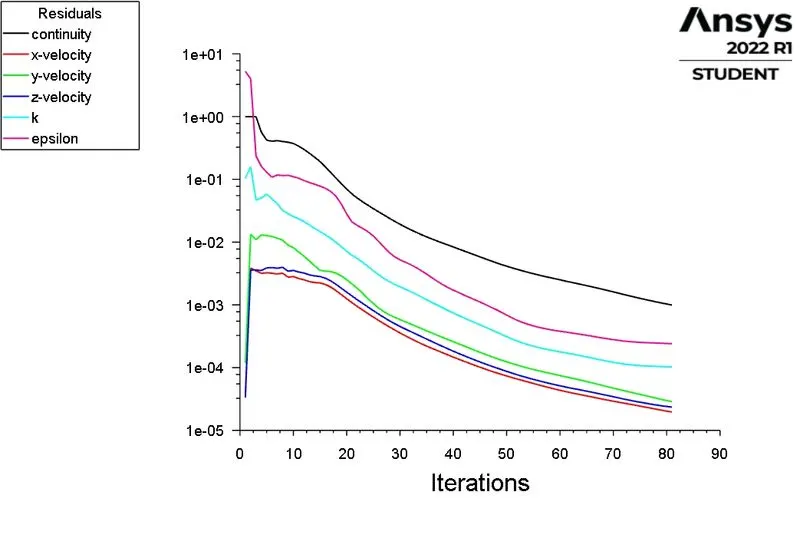
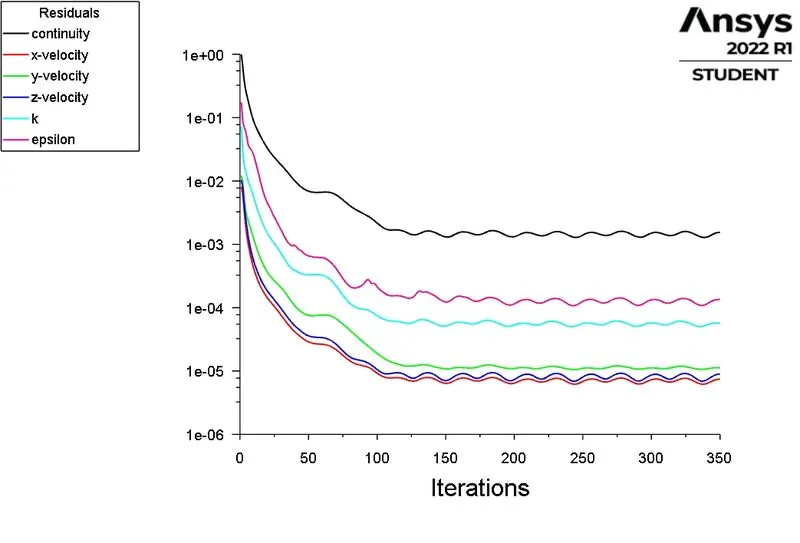
> Scaled residuals:
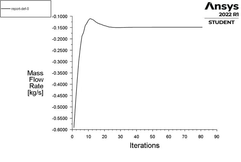
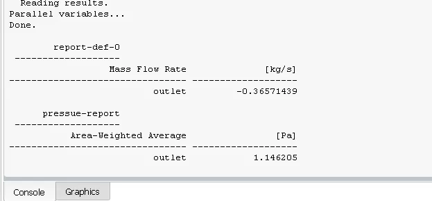
> Mass flow rate at outlet:
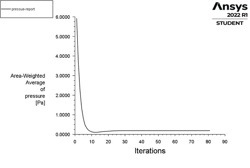
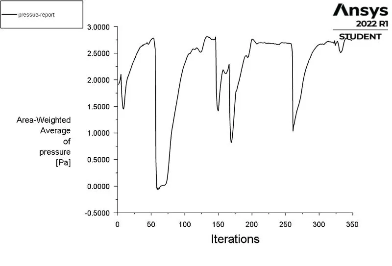
> Pressure at outlet:
> create the plane in yz plane.
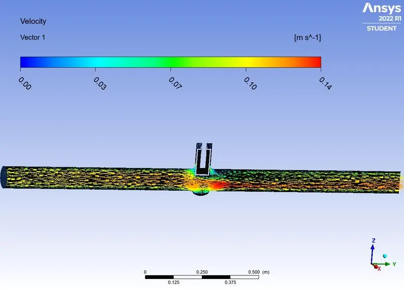
> create the velocity contour in the yz plane.
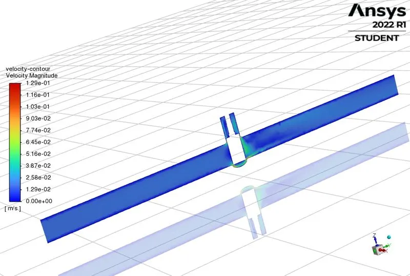
POST PROCESSING:
> CREATE THE VELOCITY VECTOR IN YZ PLANE..
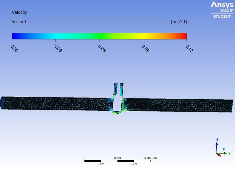
CASE 2: GATE DISC OPENING IS 20mm.
> Scaled residuals:
> Mass flow rate at outlet:
> Pressure at outlet:
> POST PROCESSING:
> create the plane in yz plane.
> create the velocity contour in the yz plane.
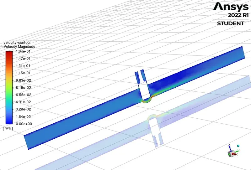
> create the velocity contour in the yz plane.
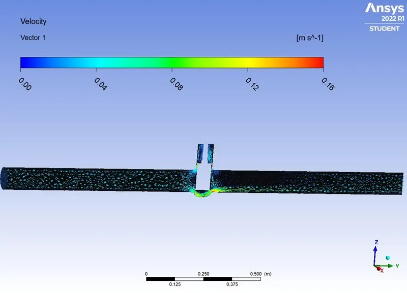
> create the velocity vector in the yz plane.
CASE 3: GATE DISC OPENING IS 30mm.
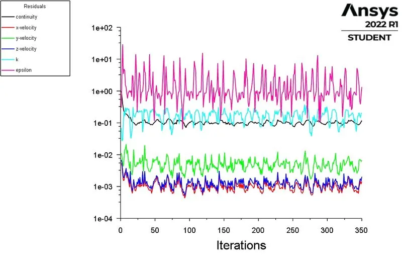
> Scaled residuals:
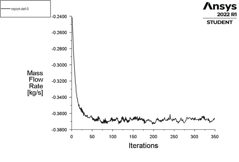
> Mass flow rate at outlet:
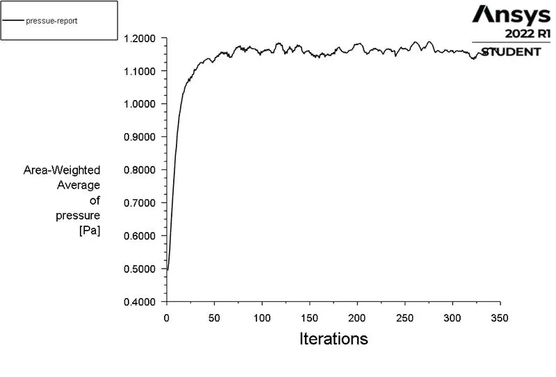
> Pressure at outlet:
POST PROCESSING:
> create the plane in yz plane.
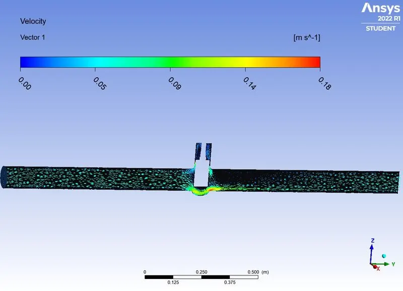
> create the velocity contour in the yz plane.
> create the velocity vector in the yz plane.
CASE 4: GATE DISC OPENING IS 40mm.
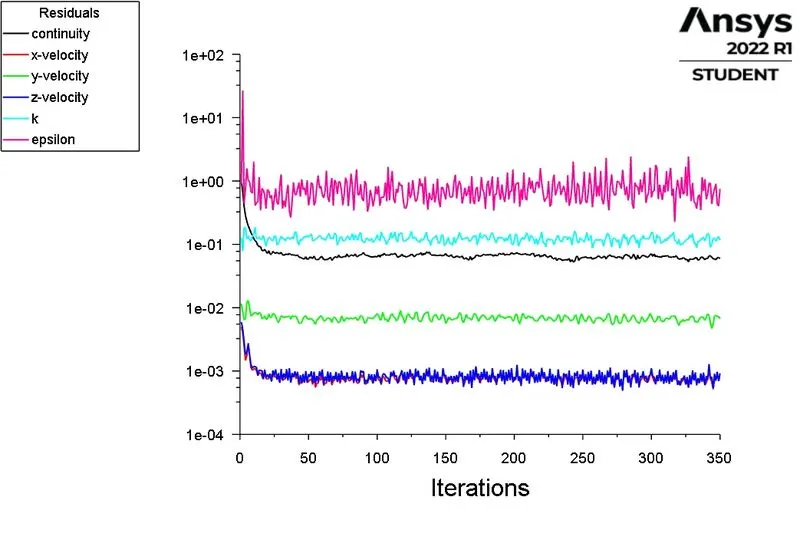
> Scaled residuals:
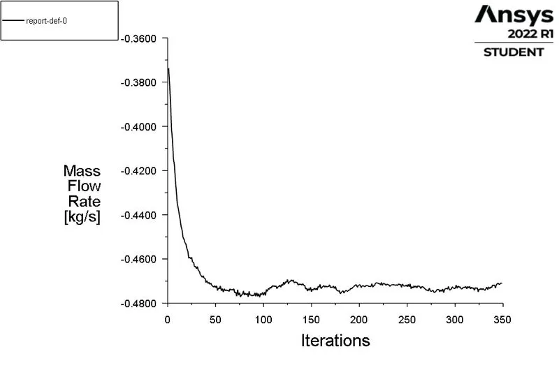
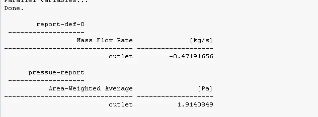
> Mass flow rate at outlet:
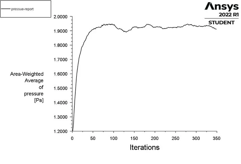
> Pressure at outlet:
POST PROCESSING:
> create the plane in yz plane.
> create the velocity contour in the yz plane.
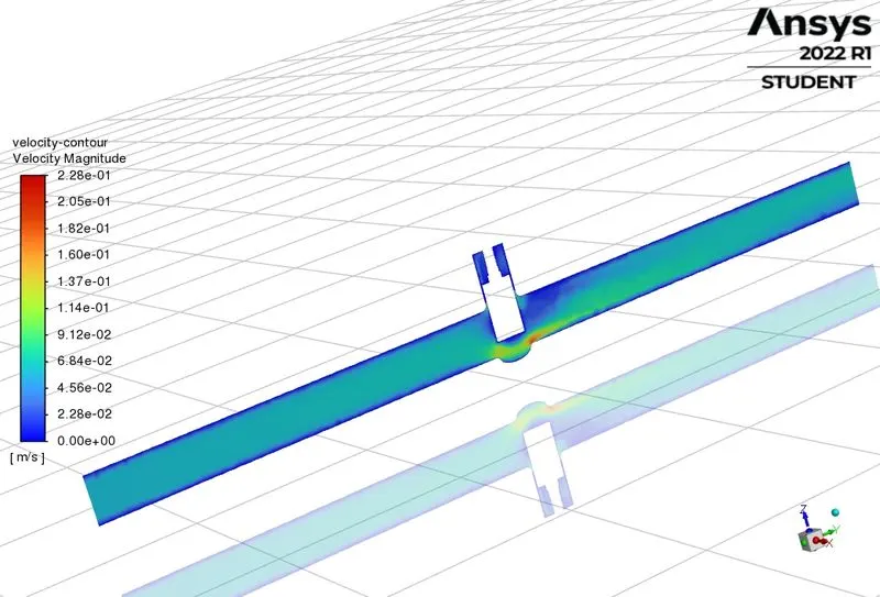
> create the velocity vector in the yz plane.
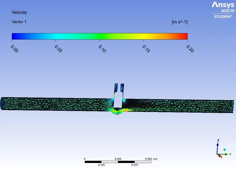
CASE 5: GATE DISC OPENING IS 50mm.
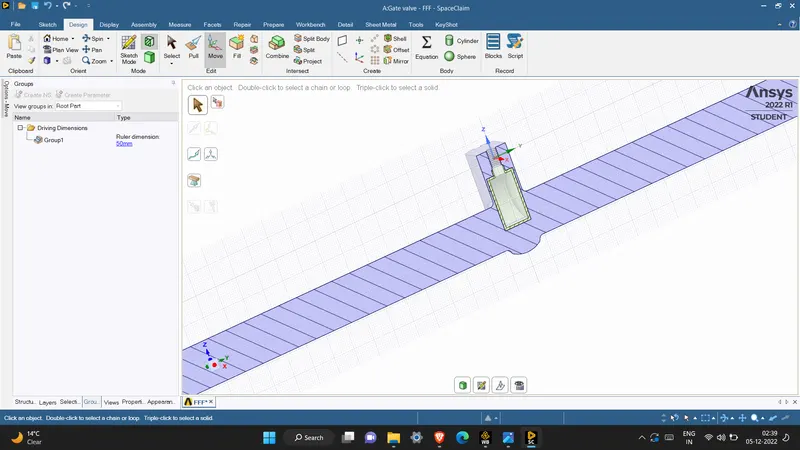
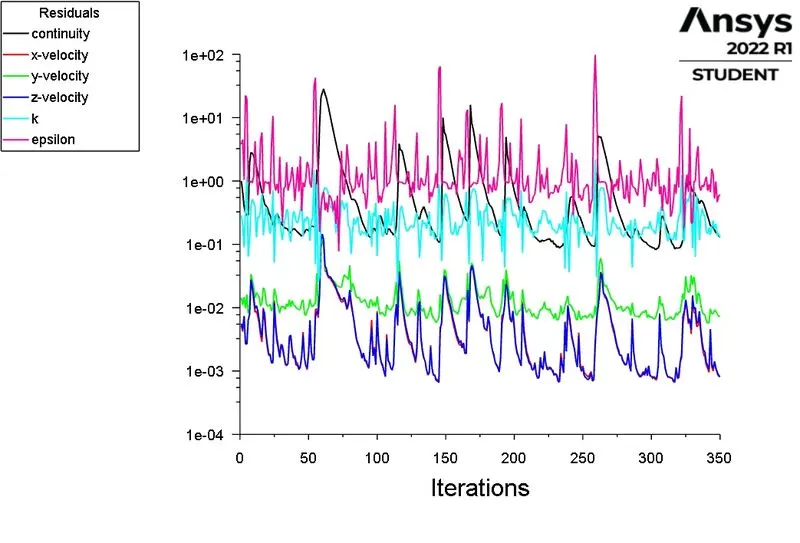
> Scaled residuals:
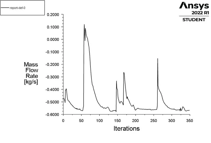
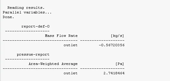
> Mass flow rate at outlet:
> Pressure at outlet:
POST PROCESSING;
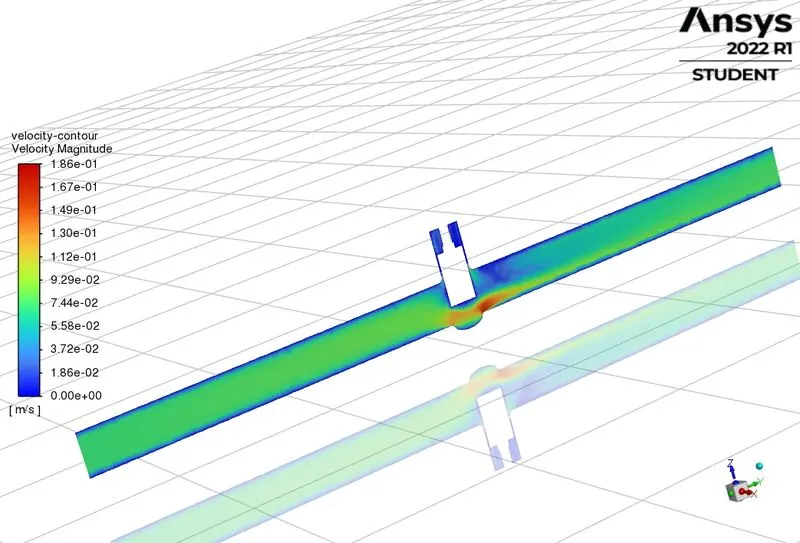
> create the plane in yz plane.
> create the velocity contour in the yz plane.
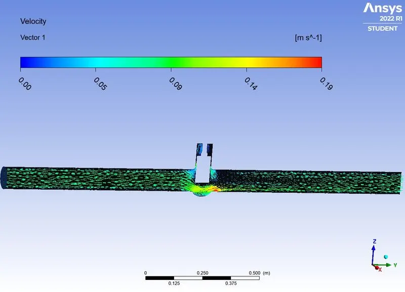
> create the velocity vector in the yz plane.
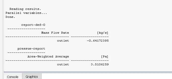
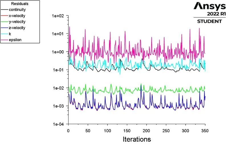
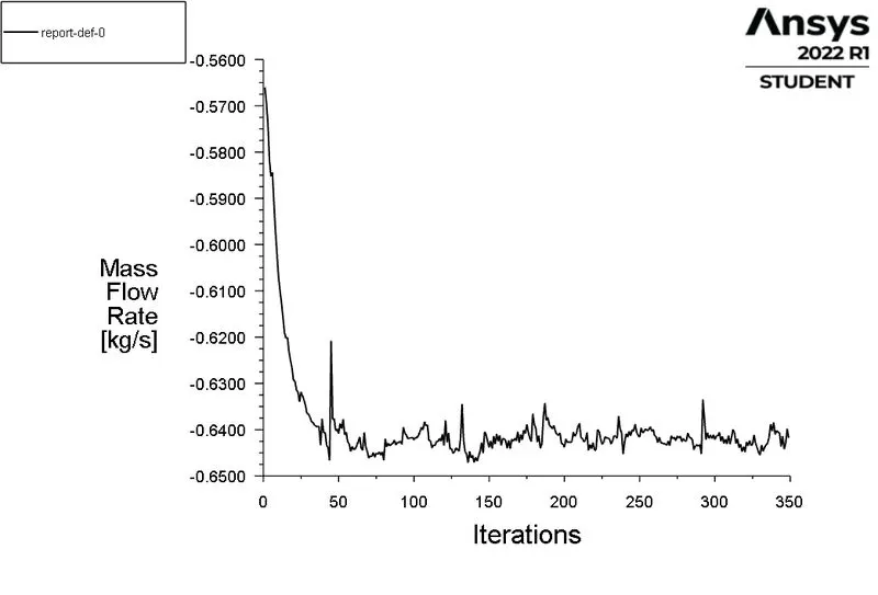
CASE 6: GATE DISC OPENING IS 60mm.
> Scaled residuals:
> Mass flow rate at outlet:
> Pressure at outlet:
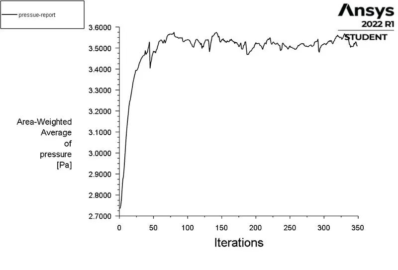
POST PROCESSING;
> create the plane in yz plane.
> create the velocity contour in the yz plane.
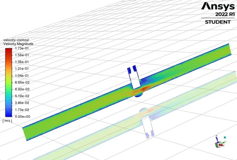
> create the velocity vector in the yz plane
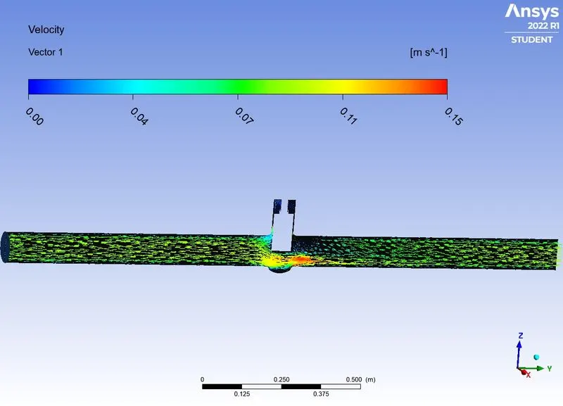
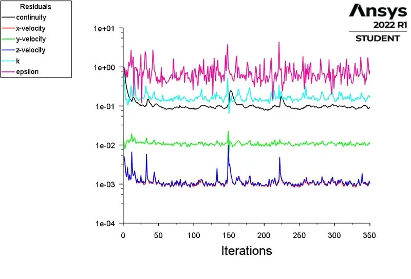
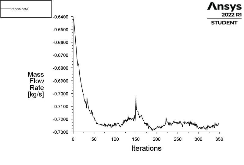
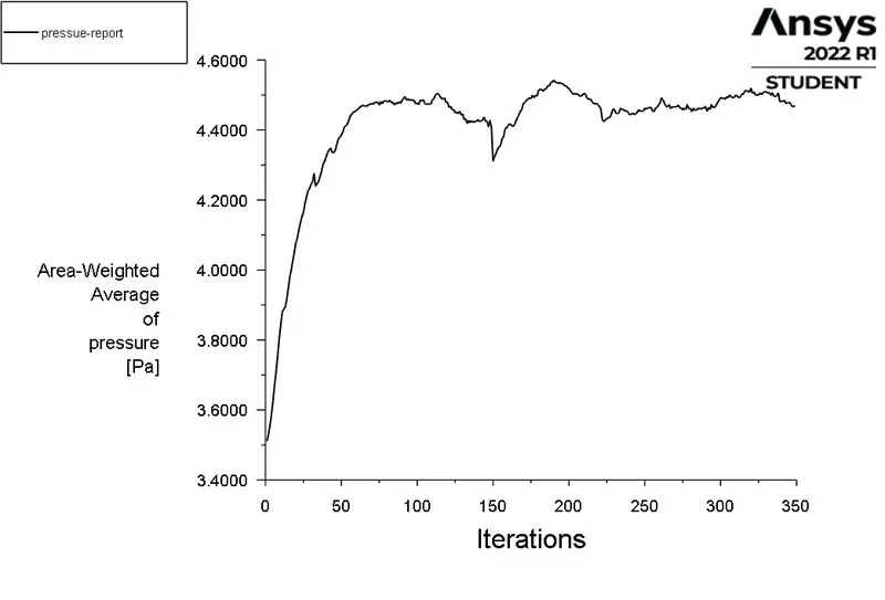
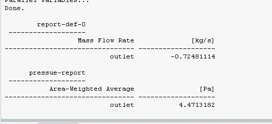
CASE7: GATE DISC OPENING IS 70mm.
> Scaled residuals:
> Mass flow rate at outlet:
> Pressure at outlet:
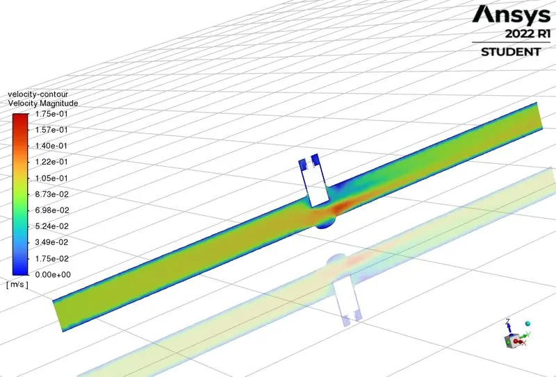
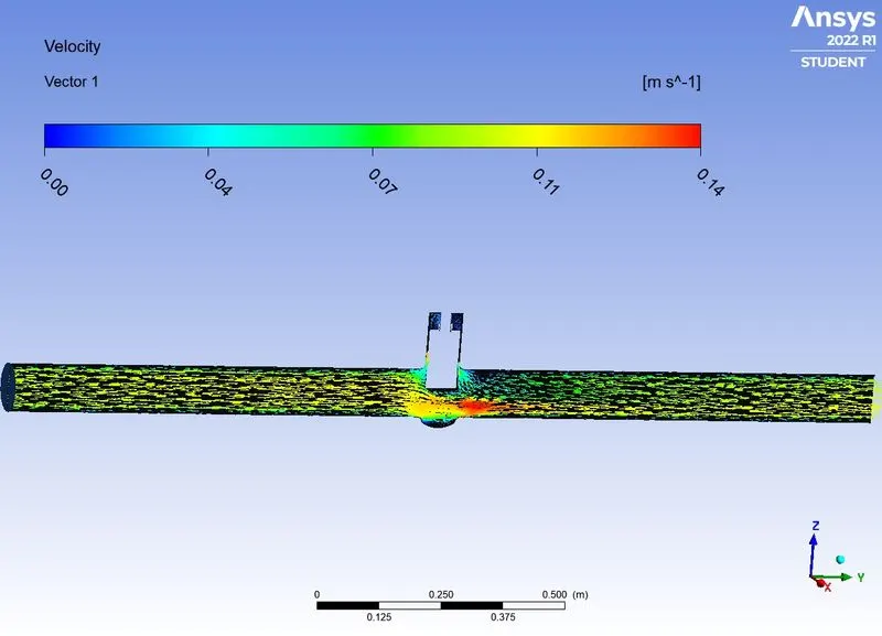
POST PROCESSING;
> create the plane in yz plane.
> create the velocity contour in the yz plane.
> create the velocity vector in the yz plane
CASE 8: GATE DISC OPENING IS 80mm.
> Scaled residuals:
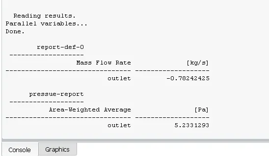
> Mass flow rate at outlet:
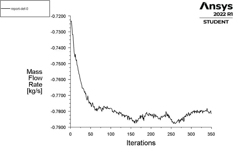
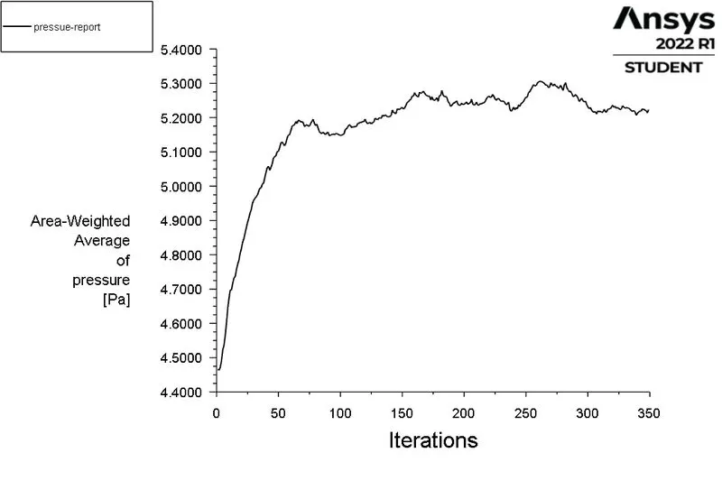
> Pressure at outlet:
POST PROCESSING;
> create the plane in yz plane.
> create the velocity contour in the yz plane.
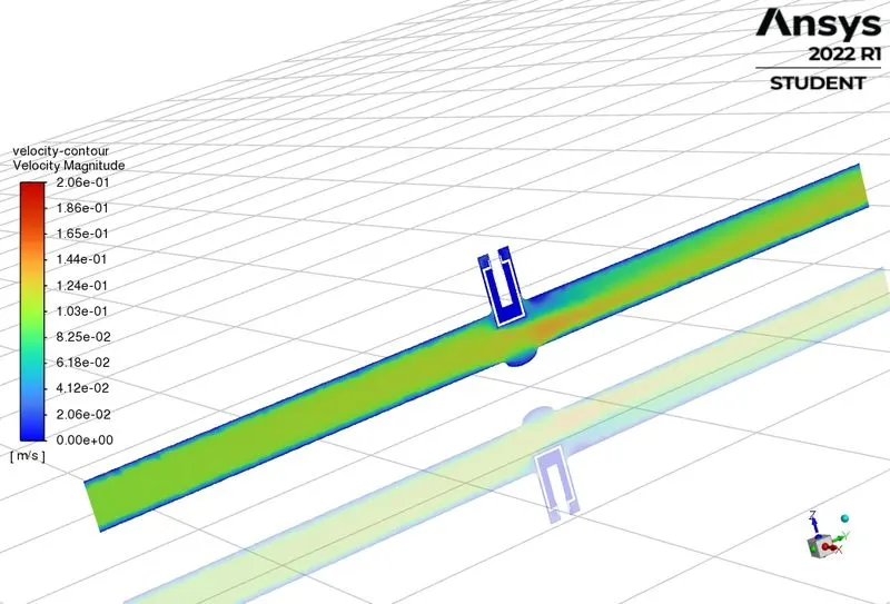
> create the velocity vector in the yz plane.
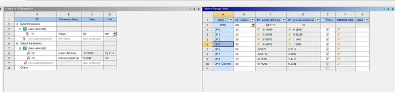
parametric study of gate valve:
The parametric study is done by clicking the parameter option. The design points are given as input with respect to different opening. We then choose the update all design point tab to get the parametric results. The fig below shows the parametric results obtained at various design points:
Computation of flow coefficient and flow factor:
The table shows the different output parameters obtained from the parametric gate valve study.
> Total pressure at inlet is 10 Pa.
> flow rate(Q) =
DESIGN POINT MASS FLOW OUTLET PRESSURE FLOW FLOW FACTOR
PRESSURE DIFFERENCE COEFFICENT
10mm 0.1484 0.1891 9.8108 17.1033 14.794
20mm 0.2403 0.4921 9.5078 27.8142 24.059
30mm 0.3657 1.1462 8.8538 43.328 37.4789
40mm 0.4687 1.8851 8.1149 59.6556 51.6021
50mm 0.5672 2.7418 7.2582 76.96124 66.5714
60mm 0.6417 3.5106 6.489 96.1936 88.230
70mm 0.7248 4.4713 5.5287 114.807 99.3084
80mm 0.7824 5.2331 4.7669 112.049 105.578
CONCLUSION:
1.The parametric study of gate valve indicated the increase in mass flow rate at the outlet section.
2.The graphical plot for mass flow rate and flow coefficient also support the simulation results.
3.The flow coefficient plays an important role in selection of valve and sizing of valve, it also determines the efficiency of the system and the pressure effect on the system.
4. Ansys fluent helps in Simulating lots of case studies through parametric case option which helps in initializing any design to make it more efficient and improve it by iterating further if changes seemed necessary.
5. Gate valve design requires extensive simulation and practical experimentation to be properly developed if required for custom cases. Luckily we have lots of standard sizes available for different kinds of uses right now which were again developed using the similar methods.
6. Cv & Kv are very important in designing Valves as their incorrect determination will damage the component and cause loss to the manufacturer.
7. Good design will smoothen the flow of fluid velocity and create less pressure rise and controling the Cv to be optimum for the required lift.